Test dynamic façade power-failure recovery and default safe state
Definition: Test dynamic façade power-failure recovery and default safe state for commissioning engineers and facility managers validating fail-safe behavior, restart sequences, and BMS logging on motorized louvers, blinds, and operable façade panels.
- Proves fail-safe positions under controlled power-loss scenarios.
- Captures times, angles, and inrush with synchronized evidence.
- Ensures BMS priorities, alarms, and recovery behave as specified.
- Interactive, commentable, export, QR code for authenticated records.
Test dynamic façade power-failure recovery and default safe state is a focused commissioning and verification procedure for operable louvers, blinds, and movable façade panels. This checklist targets fail-safe behavior, power-loss recovery, and controls integration, ensuring the building envelope reverts to its defined safe position and restarts cleanly. It addresses façade fail-safe tests, power-loss recovery verification, and BMS alarm and trend capture. By simulating mains outages and UPS depletion in a controlled manner, you confirm safe positions, braking, manual overrides, position accuracy, and staggered restart to avoid inrush trips. The scope excludes structural integrity testing, routine cleaning, and permanent electrical design changes; it concentrates only on operational testing and evidence capture per approved project specifications and authority requirements. When executed correctly, risks such as falling elements, wind-driven damage, occupant entrapment, and uncontrolled motion are significantly reduced, while handover documentation quality improves. Use this interactive checklist now: tick items, add comments, and export PDF/Excel with a secure QR link.
- This checklist enables commissioning teams, façade contractors, and facility managers to verify that motorized façade elements reach their defined safe position during power failure and recover correctly afterward. It reduces risks from wind loads, falling parts, and entrapment while creating auditable handover records.
- Follow structured simulations of mains loss and UPS depletion, synchronized BMS and power-quality measurements, and clear acceptance criteria for time-to-safe-state, position tolerance, braking effectiveness, alarm behavior, and inrush control. Capture photos, videos, logs, and signatures for traceability and future maintenance planning.
- Outcomes include verified fail-safe performance, accurate trend logs, trained operators, updated QR-linked asset labels, and a complete test package ready for client acceptance. The process supports warranty validation, operational readiness, and ongoing compliance with project specifications and authority requirements.
- Interactive online checklist with tick, comment, and export features secured by QR code.
Pre-Test Safety and Documentation
Power-Failure Simulation Setup
Default Safe State Verification
Recovery and Resynchronization
Controls and BMS Logging
Sign-off and Handover
What a safe state means for dynamic façades
Dynamic façades include powered louvers, blinds, and operable panels that must adopt a predefined safe state under power loss. The safe state is project-specific: for example, louvers may open to reduce wind pressure, or close to block debris at street level. Verify these positions against approved schedules before testing. During a controlled outage, measure time-to-safe-state with a stopwatch and record continuous video. Use a digital inclinometer to confirm final angles meet tolerance, typically within ±2°. Observe braking and any rebound to ensure spring returns or fail-safe brakes hold position. Validate manual overrides at zero volts; hand cranks should achieve the safe state without excessive force. Real-world examples show that clarified safe states reduce wind-driven damage during sudden storms and prevent entrapment near operable blinds. Clear evidence—photos, readings, and logs—supports acceptance and enables repeatable maintenance checks later.
- Confirm safe-state angles against approved schedules.
- Record time-to-safe with continuous video.
- Verify final angle within ±2° tolerance.
- Check braking and rebound do not exceed 5°.
- Prove manual override works de-energized.
Simulating power loss safely with synchronized measurements
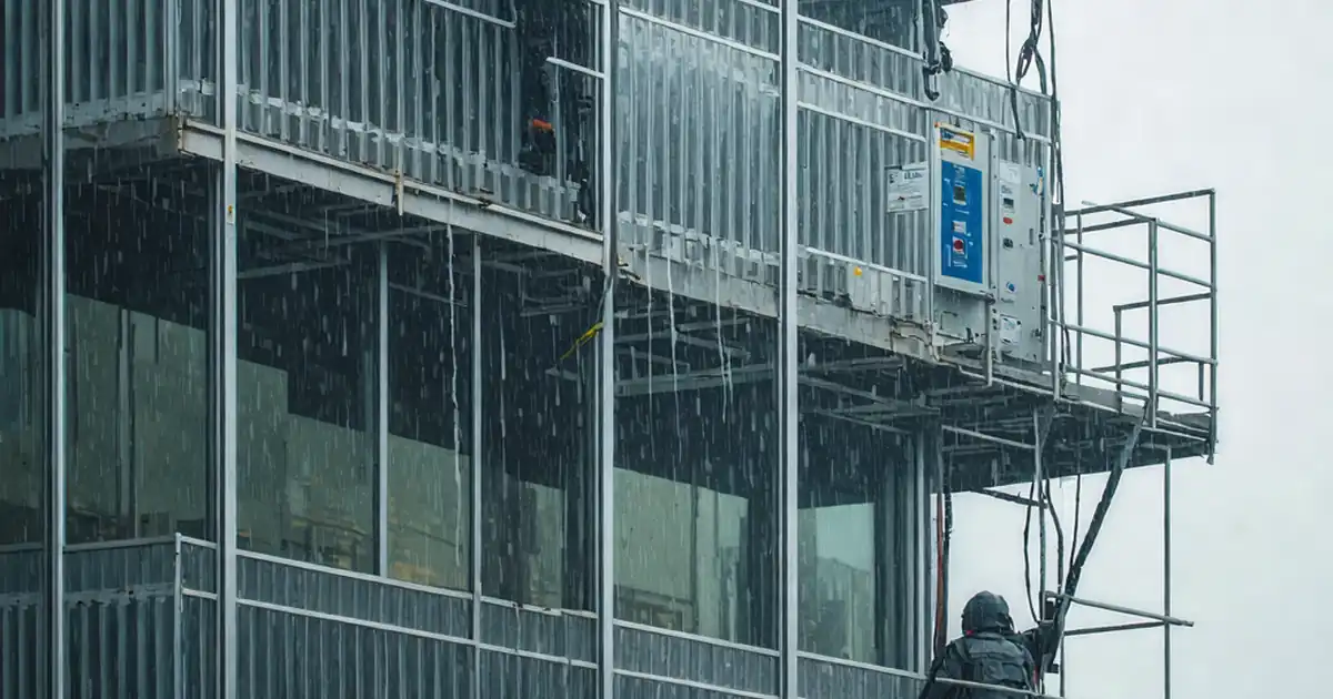
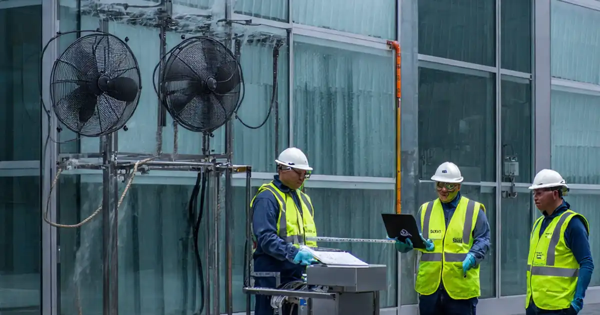
A credible test replicates how façades behave during real outages. Coordinate a switching plan, confirm lockout boundaries, and stage exclusion zones below the test bays. Install a power-quality recorder on the feeder and configure BMS trending at 1 s intervals for positions, statuses, and alarms. Time-synchronize all devices and cameras using NTP to correlate events precisely. Verify instrumentation calibration and probe ratings before touching live gear. Execute the outage under supervision, then document breaker status and timestamps. Capture video from multiple angles to observe motion and restraint behavior. Cross-check BMS trend markers with the power-quality waveform so you can trace cause and effect. On high-rise façades, monitor wind at elevation; postpone tests if wind exceeds limits. Good synchronization eliminates disputes, accelerates sign-off, and provides defensible evidence for warranty and compliance reviews.
- Use a written, signed switching plan.
- Trend BMS points at 1 s intervals.
- Time-sync cameras, BMS, and PQ recorder.
- Verify instrument calibration and probe ratings.
- Postpone testing in high winds.
Reliable recovery, resynchronization, and documentation
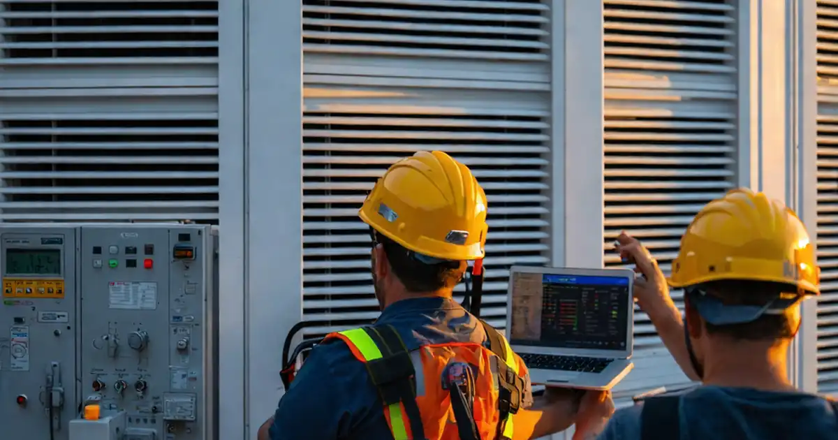
After power restoration, controllers should boot, home to references, and accept new commands without uncommanded motion. Stagger restarts to avoid inrush trips, measuring peak current with a clamp meter. Validate commanded versus actual positions with spot inclinometer checks and ensure fail-safe priorities supersede manual overrides until acknowledgments clear. Alarms must latch until an operator confirms safe status; notifications should reach stakeholders quickly. Conclude by archiving a complete evidence package: photos, videos, BMS trends, power-quality data, calibration certificates, and signed certificates. Update O&M manuals with tested safe-state settings and step-by-step recovery instructions. Apply QR labels to each asset so technicians can retrieve the latest records at the point of work. These practices transform a one-off test into a repeatable maintenance routine and provide an auditable trail for acceptance and compliance.
- Stagger restarts to limit inrush current.
- Verify homing completes within 120 seconds.
- Confirm alarms latch until acknowledgment.
- Compare commanded vs actual within ±2°.
- Archive evidence with asset IDs and timestamps.
How to use this interactive power-failure and safe-state test checklist
- Preparation: assemble tools (power-quality recorder, clamp meter, digital inclinometer, calibrated multimeter), PPE (helmet, eye protection, cut-resistant gloves, fall arrest), cameras with NTP sync, and access equipment. Confirm signed switching plan, exclusion zones, and weather limits. Verify all instruments are in calibration and batteries charged.
- Using the Interactive Checklist: start interactive mode, tick each item as completed, attach photos/videos and meter screenshots, and add comments for deviations or defects. Cross-reference asset IDs via QR labels. When finished, export to PDF/Excel for distribution and archive the live, commentable record.
- Sign-Off: obtain digital signatures from the contractor, client representative, and commissioning engineer. Confirm that evidence files are linked and QR labels point to the final record. Distribute the signed package and store it in the project’s controlled document repository.
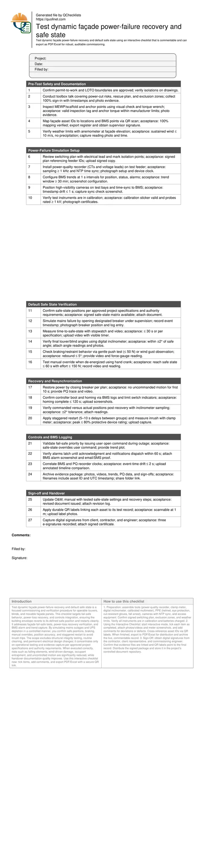
Call to Action
- Start Checklist Tick off tasks, leave comments on items or the whole form, and export your completed report to PDF or Excel—with a built-in QR code for authenticity.
- Download Excel - Dynamic Façade Power-Failure Recovery & Safe-State Test
- Download PDF - Dynamic Façade Power-Failure Recovery & Safe-State Test
- View Image - Dynamic Façade Power-Failure Recovery & Safe-State Test
Cite & Embed
“Dynamic Façade Power-Failure Recovery & Safe-State Test by Quollnet”
with a link to
this source page.
FAQ
Question: How many façade bays should be tested during a power-failure recovery exercise?
Question: What if wind speeds are high on the scheduled test day?
Question: Our units did not reach the defined safe state—what should we do?
Question: Does a UPS or battery backup change how we test recovery?
Related Articles
Broader reading and guidance connected to this checklist topic.


Open Ncrs At Taking-over / Dlp: What Happens At Handover And How To Escalate
Related Checklists
Keep the workflow moving with nearby templates chosen from similar checklist content.