
Method Statement: Installation of Computer Room Air Conditioning (CRAC) Units in Data Centers – Method Statement
AI-assisted method statement with matching ITP, PDF download, and Excel export.
More than a static template
Unlike a downloadable Word or PDF template, this method statement is an AI-assisted editable starting point connected directly to a matching Inspection and Test Plan. Every section is structured, project-adaptable, and ready to export.
- AI-assisted drafting — Customize every section with AI for your specific project scope.
- Linked ITP — A matching inspection and test plan is generated alongside the method statement.
- Multiple export formats — Download as a formatted PDF or editable Excel spreadsheet.
- Editable starting point, not a final document — Review, verify, and adjust all content against your project requirements before use.
Static template vs. Quollnet workflow
| Feature | Static template | Quollnet |
|---|---|---|
| Project-specific content | Manual fill-in required | AI-assisted customization |
| Linked ITP | Separate document, no link | Matching ITP included |
| Export formats | Usually PDF only | PDF and Excel |
| Structured sections | Free-form layout | 13 standardized sections |
| Saved to your account | Local file only | Cloud-saved, reusable |
| Content accuracy | You verify everything | AI-assisted, you still verify |
| Cost | Often free but time-intensive | Free to customize and download |
What you can customize
When you save this method statement to your account, every section becomes editable. The following 13 sections are included:
- Scope — Defines the activity and its boundaries.
- References — Standards, specifications, and drawings.
- Responsibilities — Roles and accountabilities.
- Resources — Labour, plant, and equipment summary.
- Materials — Materials and compliance requirements.
- Equipment — Tools and equipment details.
- Prerequisites — Hold points and pre-conditions.
- Method sequence — Step-by-step construction sequence.
- Safety controls — HSE risk controls and PPE.
- Environmental controls — Environmental mitigation measures.
- QA/QC — Quality inspection and test requirements.
- ITP — Inspection and Test Plan table (has its own page).
- Attachments — Referenced drawings and documentation.
Why this method statement is used
This method statement is used to define and communicate the approved procedure for carrying out method statement: installation of computer room air conditioning (crac) units in data centers on site. It ensures the work is planned in advance, the correct resources and controls are in place, and all personnel understand responsibilities, sequence, quality requirements, and safety controls before work begins. It aligns site execution with the documented scope and acceptance expectations.
Who uses this method statement
This method statement is used by contractors, site supervisors, project engineers, QA/QC engineers, HSE officers, consultants, and client representatives. It serves as a shared reference for planning, execution, supervision, inspection, and approval of the activity on site.
When it is prepared and submitted
The method statement is prepared before the work activity starts and submitted as part of the pre-construction documentation package for review and approval.
Who reviews or approves it
The method statement is usually submitted to the client representative, consultant, resident engineer, or project management consultant for review and approval before the work commences.
Important approval note
This method statement is an AI-assisted editable starting point, not a pre-approved document. Before use on any project, all content must be reviewed and approved by the relevant parties (superintendent, principal contractor, or client representative) in accordance with your contract and project quality plan.
For example: if your specification requires a departure from a referenced standard, that departure must be documented and approved separately — this method statement will not capture that automatically. Always verify against your applicable drawings, specifications, and regulatory requirements.
Method statement content
Scope
Inclusions
- Delivery, offloading, rigging, placement, leveling, and anchorage of CRAC units.
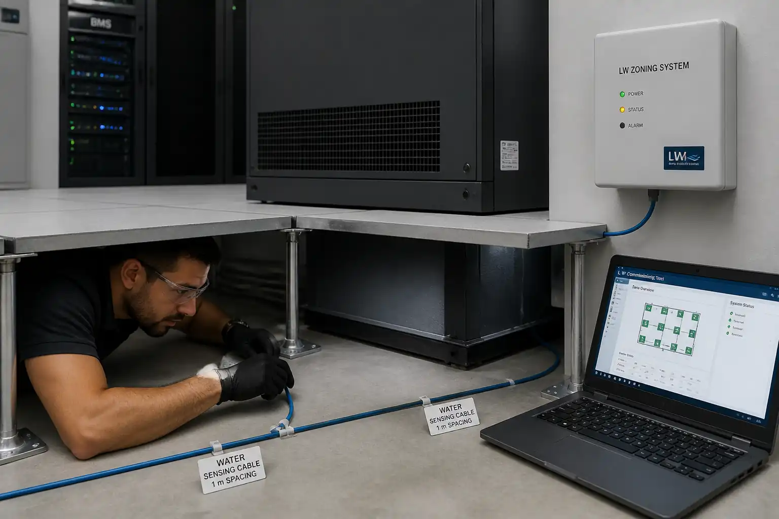
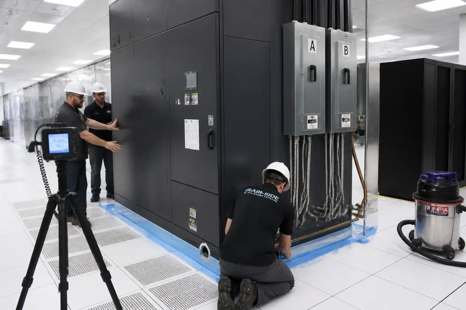
- Interface with raised floor: framing/stringer alignment, floor cut-outs, and precision underfloor discharge sealing.
- Humidification water line connections (make-up, isolation, filtration, backflow prevention) and condensate drainage with traps/priming and heat-trace if required.
- Electrical works: dual power feed (A/B) terminations, functional interlocks/ATS or dual-corded schemes, earthing/bonding, labeling, and verification testing.
- Controls/BMS integration: sensors, alarms, and communications cabling; point-to-point checks.
- Cleanroom-grade QA/QC protocols: ISO 14644-oriented cleanliness controls, particle counts, and contamination prevention during installation.
- Commissioning assistance: operational checks, airflow and temperature performance verification, and as-built documentation.
Exclusions
- Structural strengthening beyond CRAC pedestal/rails and anchor installation.
- Building-wide BMS programming and network commissioning unless stated.
- Permanent firestopping beyond penetrations created by this scope.
- Refrigerant piping beyond unit connections where field-piped split systems are not part of this package.
Interfaces
- Civil/structural for slab load bearing and seismic supports [Verify per project specifications].
- Electrical for feeders, breakers, and power shutdown coordination.
- Plumbing for water supply quality/pressure and drain tie-ins.
- IT/Operations for access restrictions and outage windows.
- Commissioning authority for witnessing and performance validation.
References
| Document Type | Reference / Number | Revision | Notes |
|---|---|---|---|
| ISO 14644-1 and ISO 14644-3: Cleanrooms and associated controlled environments (classification and test methods) | Particle count acceptance and test methods for cleanliness checks. | ||
| IEC 60364 (Low-voltage electrical installations) incl. parts for verification/testing and earthing/bonding | Used for insulation resistance, polarity, earth continuity tests, and functional verification. | ||
| EN 1992-4: Design of fastenings for use in concrete (ETA anchors) and EN 1998 (seismic) [if applicable] | Anchorage design and seismic restraint where specified. | ||
| BS EN 12825: Raised access floors | Raised floor performance, pedestals/stringers, loading/deflection limits. | ||
| BS EN 378 (Refrigerating systems and heat pumps – Safety and environmental requirements) | Applicable to DX CRAC units for refrigerant handling, testing, evacuation, and leak detection. | ||
| ISO 13585: Brazing – Qualification of brazers and brazing operators | If field brazing of refrigerant lines is within scope. | ||
| BS EN 1717: Protection against pollution of potable water in water installations and requirements for devices to prevent backflow | Backflow prevention for humidifier make-up water. | ||
| IEC 60228 (Conductors), IEC 60445 (Basic and safety principles for man-machine interface, marking and identification) | Cabling, conductor sizing identification, and labeling. | ||
| EN 1366-3: Fire resistance tests for service installations – Penetration seals | Firestopping for penetrations made by this scope where required. | ||
| Project Specifications and Approved OEM Manuals | Prevail where more stringent; verify setpoints, water quality, electrical details [Verify per project specifications]. |
Responsibilities
| Role | Responsibility | Name / Party |
|---|---|---|
| PM | Project Manager | Main Contractor |
| CM | Construction Manager | Main Contractor |
| QA/QC | QA/QC Engineer | Main Contractor |
| ES | Electrical Supervisor | Main Contractor |
| MS | Mechanical Supervisor | Main Contractor |
| CE | Controls Engineer | Specialist Subcontractor |
| RL | Riggers/Logistics Lead | Specialist Subcontractor |
| HSE | HSE Officer | Main Contractor |
| OEM Rep | Manufacturer’s Representative | Vendor |
Resources
| Resource Type | Description | Quantity | Remarks |
|---|---|---|---|
| Rigging team | As required | Lift plan approved prior to works | |
| Electrical team | 2–4 | LOTO trained | |
| Mechanical/Piping team | 2–3 | Brazers qualified to ISO 13585 if brazing DX lines | |
| Controls team | 1–2 | Familiar with site BMS protocols | |
| Testing & balancing | 1–2 | Use calibrated balometer/manometers | |
| Cleanroom cleaners | 1–2 | HEPA vacuums, tack mats, lint-free wipes |
Materials
| Material | Specification / Grade | Quantity | Remarks |
|---|---|---|---|
| CRAC unit | Capacity, footprint, electrical rating per drawings [Verify per project specifications] | As per BOQ | With OEM seismic kit where specified |
| Underfloor discharge sealing kit | Airtight; temperature/humidity resistant; low-VOC | As required | Closed-cell, non-shedding |
| Raised floor sealing accessories | Compliant with BS EN 12825 interfaces | As required | Antistatic rating as specified |
| Humidification water line components | EN 1717 compliant backflow device; PN rating ≥ system design + margin [Verify] | As required | Water quality per OEM |
| Condensate drain components | Non-corroding; firestopping at penetrations per EN 1366-3 | As required | Slope ≥1% to drain |
| Anchors and fasteners | EN 1992-4 design basis; torque per ETA datasheet | As required | Stainless if in corrosive areas |
| Refrigerant piping (if applicable) | Pressure rating per BS EN 378 and OEM [Verify] | As required | Brazing alloy per OEM; flux-free for refrigerant duty |
| Electrical materials | IEC 60228 conductors; IEC 60364 installation | As required | Halogen-free LSZH where specified |
| Firestopping materials | EN 1366-3 rated to barrier FRL [Verify] | As required | Compatible with substrate and services |
Equipment
| Equipment | Capacity / Type | Quantity | Inspection Required |
|---|---|---|---|
| Forklift/gantry/crane & skates | As per lift plan | Pre-use inspection, certification valid | |
| Rotary hammer/drill with dust extraction | Check RPM and bit condition | ||
| Calibrated torque wrench | Range per anchors | Calibration certificate | |
| Insulation resistance tester (megger) | Calibration certificate | ||
| Pressure/vacuum/leak test kit | Calibration certificates | ||
| Airflow/pressure instruments | Calibration certificates | ||
| Particle counter | Calibration certificate | ||
| HEPA vacuum cleaners | Filter integrity checked | ||
| Pressure pump/gauges and water test kit | Calibration certificates |
Prerequisites
- Approved shop drawings, coordination drawings (reflecting underfloor services, stringer layout, CRAC footprint), and OEM submittals.
- Lift/rigging plan approved; access route survey confirming slab capacities, doorway clearances, and raised floor load ratings per BS EN 12825.
- Permits to Work: Electrical LOTO, Hot Work (if brazing), Confined Space (if applicable to underfloor entries), Work at Height (if using gantry/crane near edges) [Verify per project HSE plan and local regulations].
- HSE documentation: Task Risk Assessments, Method Statement briefing, Toolbox Talks, SDS for sealants/adhesives.
- Calibrations current for all test equipment; anchor approvals on site; consumables batch certificates.
- Verification of utility points: A/B electrical feeders de-energized and locked/tagged; water supply pressure/quality confirmed; drains available and tested free-flow.
- Room readiness: enclosure to minimize dust; temporary protection (poly sheeting), tack mats; housekeeping plan in place.
- BMS point list approved, network addresses reserved, cabling routes agreed; IP addressing or BACnet/Modbus node plan confirmed.
- Seismic requirements clarified; support/anchorage details approved by Structural Engineer [Verify per project specifications].
- Outage/energization plan agreed with Client/Operations; notification issued.
- Pre-delivery inspection of CRAC units for damage, correct model/options, and accessories.
- Verify OEM restrictions for megger testing and sensors removal before insulation tests.
- Verify humidity water quality and filtration requirements per OEM (e.g., conductivity range, hardness, silica) [Verify per project specifications and OEM].
Method Sequence
| Step | Activity | Description | Responsibility | Inspection / Hold Point |
|---|---|---|---|---|
| 1 | Pre-Installation Verification | Confirm drawings/OEM manuals, survey location, mark CRAC footprint, underfloor obstructions, and cable/water/drain routes. | Mechanical & Electrical Supervisors | Joint site walkdown |
| 2 | Room Cleanliness Preparation | Install temporary dust barriers, tack mats; HEPA vacuum area and underfloor plenum. Remove debris. | Site Supervisor/Cleaning team | Visual + particle baseline if required |
| 3 | Rigging and Placement | Offload and move CRAC via skates/gantry. Position on slab/rails without damaging raised floor. Maintain control with taglines. | Riggers/Logistics Lead | HSE oversight; equipment certification check |
| 4 | Leveling and Anchorage | Level unit to OEM limits using shims/leveling feet (typ. ±1 mm/m). Drill holes and install ETA anchors per EN 1992-4. Torque to datasheet. | Mechanical Supervisor | Hold point before torquing |
| 5 | Raised Floor Interface | Align stringers/cut-outs; install brush grommets and blanking panels. Reinforce pedestals if needed per BS EN 12825. | Construction Manager | Visual + measurement |
| 6 | Underfloor Discharge Sealing | Install continuous neoprene/EPDM gasket around CRAC base to floor interface; seal cable openings. Smoke-pencil and DP spot checks. | Mechanical Supervisor | Witness point |
| 7 | Humidification Water Connection | Install isolation valve, Y-strainer, pressure gauge, backflow preventer; connect flexible hose/hard pipe to OEM stub. Flush lines before final tie-in. | Mechanical/Piping Team | Hold point before closing up |
| 8 | Condensate Drain Installation | Provide P-trap and priming; slope ≥1% to drain; heat-trace/insulate if ambient below dewpoint risk. Water test. | Mechanical/Piping Team | Witness |
| 9 | DX Refrigerant (If Applicable) | Brazed joints by qualified brazers with nitrogen purge; pressure test with dry N2; evacuate to ≤500 microns; charge per OEM. | Mechanical Supervisor | Hold during pressure test and evacuation |
| 10 | Electrical A/B Feed Termination | Verify isolation; pull cables; terminate to dedicated A and B inputs/ATS; ensure segregation. Bond earths. Label per scheme. | Electrical Supervisor | Hold before energization |
| 11 | Electrical Verification Testing | With controls isolated as needed: insulation resistance, earth continuity, functional interlock/ATS tests, no-backfeed check. | Electrical Supervisor/QAQC | Witness by Consultant |
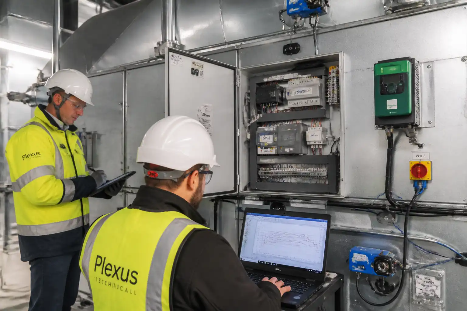
| 12 | Controls/BMS Integration | Connect sensors, network cables; verify I/O and alarms; trend key parameters. | Controls Engineer | Witness |
| 13 | Pre-Functional Checks | OEM representative inspects filters, belts (if any), fans, humidifier, valves, safeties, setpoints. | OEM Rep/Commissioning Lead | Hold |
| 14 | Start-up and Performance Verification | Energize sequentially A then B feeders; start CRAC under supervision; stabilize; measure airflow, supply air temp/RH, plenum DP. | Commissioning Lead/TAB | Witness by Consultant |
| 15 | Cleanliness and Closeout | HEPA vacuum; wipe-down with lint-free cloth; remove debris; perform ISO 14644 particle count. | QA/QC & Cleaning team | Witness |
| 16 | As-Builts and Training | Mark-up drawings; capture test results; deliver O&M; train operations staff. | Project Engineer/OEM Rep | Document review |
Safety Controls (Task-Specific)
For each hazard, controls are listed as: hazard, consequence, engineering/procedural control, PPE, collective measure, inspection/permit/supervision requirement.
- Heavy lifting/rigging of CRAC units
- Consequence: crush injuries, dropped load, floor collapse.
- Control: Approved lift plan; rated lifting points; spreader beams; check raised floor capacity; remove panels and use temporary bridging where needed.
- PPE: Hard hat, safety boots, cut-resistant gloves, eye protection.
- Collective: Exclusion zone with barriers and spotters; taglines to control sway.
-
Inspection/Permit: Pre-use inspection of lifting gear; valid certifications; Lift permit; supervision by appointed person [Verify per project HSE plan and local regulations].
-
Raised floor work and panel removal
- Consequence: trips/falls, foot entrapment, panel collapse.
- Control: Use panel lifters; install temporary edge protection; do not overload pedestals; reinstate panels promptly.
- PPE: Safety boots, gloves.
- Collective: Temporary covers/bridges, warning signage.
-
Inspection/Permit: Daily floor inspection; CM sign-off.
-
Electrical energization and testing (A/B feeds)
- Consequence: electric shock, arc flash, unintended backfeed.
- Control: LOTO; prove dead; insulated tools; test per IEC 60364; verify no cross-ties between A/B; OEM-compliant sequencing.
- PPE: Arc-rated clothing (as required), insulated gloves, eye/face protection.
- Collective: Barriers around live panels; keep non-essential staff clear.
-
Inspection/Permit: Electrical PTW; testing by licensed electricians; supervision by Electrical Supervisor.
-
Hot works (brazing DX lines)
- Consequence: fire, burns, fumes.
- Control: Hot work permit; fire blankets; fire watch; nitrogen purge to prevent oxidation; extinguishers on hand; no brazing near combustibles.
- PPE: Welding helmet/shield, heat-resistant gloves, FR clothing.
- Collective: Local ventilation; fire-resistant screens.
-
Inspection/Permit: Hot work permit; gas cylinder checks; post-work fire watch (≥30 min) [Verify per project HSE plan].
-
Compressed gas (N2) pressure testing
- Consequence: hose whip, burst fittings, asphyxiation in confined plenum.
- Control: Regulators with relief; rated hoses; step-up pressurization; leak checks with approved solutions; monitor O2 if in confined areas.
- PPE: Eye protection, gloves, hearing protection if venting.
- Collective: Exclusion zone during pressurization.
-
Inspection/Permit: Pressure test permit; calibrated gauges.
-
Working in underfloor plenum
- Consequence: restricted access, trip hazards, poor lighting, dust inhalation.
- Control: Access only at designated panels; lighting; housekeeping; avoid simultaneous wet works.
- PPE: Hard hat bump cap as needed, gloves, eye protection, dust mask (P2) if dust potential.
- Collective: Attendant/spotter outside plenum.
-
Inspection/Permit: Confined space assessment if criteria met; PTW if required.
-
Chemical exposure (sealants/cleaners)
- Consequence: skin/eye irritation, VOC inhalation.
- Control: Use low-VOC products; follow SDS; apply minimal quantities; ensure ventilation.
- PPE: Nitrile gloves, goggles, half-mask with organic vapor cartridges if required.
- Collective: Spill kits available.
-
Inspection/Permit: SDS review; COSHH/chemical permit where applicable.
-
Noise and vibration from tools
- Consequence: hearing loss, hand-arm vibration syndrome.
- Control: Low-vibration tools; task rotation; limit exposure time.
- PPE: Hearing protection.
- Collective: Time-of-day controls to avoid operations impact.
-
Inspection/Permit: HSE monitoring; tool maintenance records.
-
Refrigerant exposure (DX)
- Consequence: frostbite, asphyxiation, cardiac sensitization (some refrigerants).
- Control: Handle cylinders upright; leak detection; avoid confined spaces; follow BS EN 378 limits.
- PPE: Cryo gloves, goggles.
- Collective: Ventilation; refrigerant detectors where required.
-
Inspection/Permit: Cylinder inspection; F-Gas certification where applicable [Verify per local regulations].
-
Legionella/biogrowth risk in humidification systems
- Consequence: respiratory illness.
- Control: Use OEM-specified treatment/UV or clean steam; maintain temp; periodic flushing.
- PPE: Gloves, eye protection.
- Collective: Closed systems preferred; documented water hygiene regime.
- Inspection/Permit: Water hygiene plan approval.
Environmental Controls
- Dust and particulate control
- Risk: contamination of IT equipment and failure to meet ISO 14644 targets.
- Controls: Enclose work area; HEPA vacuum; tack mats; prohibit dry sweeping; use pre-cleaned materials.
-
Monitoring: Particle counts at start/end of shift during critical phases.
-
Noise
- Risk: disturbance to adjacent operations.
- Controls: Schedule noisy works off-hours; use low-noise tools; acoustic screens if required.
-
Monitoring: Spot dB measurements [Verify per project HSE plan].
-
Waste management
- Risk: improper disposal of packaging, metal scraps, and chemical containers.
- Controls: Segregate recyclable packaging; dispose sealant containers per SDS; refrigerant handling per BS EN 378.
-
Records: Waste transfer notes.
-
Water discharge
- Risk: flooding or contamination via test water.
- Controls: Use controlled discharge to sanitary drains; use drip trays; plug/containment during connections.
-
Monitoring: Visual during hydro/drain tests.
-
Refrigerant handling (DX)
- Risk: greenhouse gas release.
- Controls: Certified handlers; recovery units; leak-tight practices; log refrigerant quantities.
-
Records: Refrigerant logbook; recovery certificates.
-
Chemical use and VOCs
- Risk: indoor air quality deterioration.
- Controls: Low-VOC sealants/adhesives; minimal quantities; localized ventilation; close containers.
-
Monitoring: Odor and worker feedback; stop work if IAQ complaints arise.
-
Energy and commissioning
- Risk: unnecessary run hours during testing.
- Controls: Consolidate tests; pre-checks to avoid repeat runs; trend energy KPIs post-commissioning.
QA/QC
- Submittal control: Use latest approved shop drawings/OEM manuals; deviations via RFI.
- Calibration: All instruments within validity; maintain calibration register.
- Material verification: Check nameplates, model options, MEP connection sizes, anchor approvals, and firestop certificates before installation.
- Workmanship: Clean cuts, burr-free edges; no debris in plenum; gaskets continuous; labels permanent and legible.
- Testing frequencies:
- Anchor torque: 100% of anchors; record value and wrench ID.
- Electrical tests: 100% of CRAC feeds and control circuits.
- Hydrostatic water line: 100% of humidification lines; 2 h hold.
- Condensate drain test: 100% with ≥5 L discharge.
- DX systems: 100% pressure/vacuum/leak.
- Particle counts: Minimum at 3 locations per CRAC zone (return side, supply plenum, room center) pre- and post-clean.
- Airflow/TAB: 100% units; sample 10–20% of floor grilles per unit, including worst-case farthest points [Verify per project specifications].
- Acceptance metrics (typical; verify per contract):
- Leveling: ±1 mm/m (or OEM tighter).
- Plenum differential pressure: within ±10% of design during test.
- Airflow: within ±10% of design CFM.
- Temperature/RH: supply 18–27°C; dew point 5.5–15°C (ASHRAE TC 9.9) [Verify].
- ISO cleanliness: typically Class 8 or better during handover [Verify].
- Electrical: IR ≥1 MΩ at 500 VDC (or per OEM), PE continuity <0.5 Ω, correct polarity and phase rotation.
- Documentation: ITP checklists, photos, redlines, torque logs, test certificates, OEM start-up sheets, training attendance, O&M manuals.
- Nonconformance: Record via NCR; corrective action and re-test before proceeding to next stage.
- Hold/Witness: As indicated in ITP; no work to proceed past Hold points without written release.
Attachments
- Approved shop drawings and coordination drawings (latest revision)
- OEM data sheets, installation manuals, wiring diagrams
- Lift/rigging plan and permits
- Anchor approvals (ETA/ICC), torque datasheets
- Calibration certificates for all test instruments
- Pressure/hydro test certificates and DX test sheets (if applicable)
- Electrical test reports (IEC 60364)
- BMS point lists and P2P check sheets
- TAB reports (airflow and DP measurements)
- Particle count logs (ISO 14644)
- Firestopping product approvals and installation records
- As-built drawings (PDF + native CAD/BIM)
- O&M manuals and training attendance records
This content is a read-only public reference. Download or customize to get an editable version.
ITP preview
The first inspection activities from the linked ITP for Method Statement: Installation of Computer Room Air Conditioning (CRAC) Units in Data Centers:
| Activity | Inspection / Test | Acceptance Criteria | Responsibility | Record |
|---|---|---|---|---|
| Pre-start approvals | Verify approved drawings, method, risk assessments, permits | All approvals current; permits open | Prestart checklist | |
| Delivery inspection | Check CRAC model/options, damage, accessories | Matches submittal; no damage | Delivery IR/photos | |
| Location and layout verification | Measure footprint vs. marks; clearance to walls/cableways | Within ±5 mm; OEM service clearances met | Layout report |
Showing 3 of 19 inspection activities. View full ITP →
Related Inspection and Test Plan
An Inspection and Test Plan (ITP) is available for Method Statement: Installation of Computer Room Air Conditioning (CRAC) Units in Data Centers. The ITP defines the inspection activities, acceptance criteria, hold and witness points, responsible parties, and records required to verify the work described in this method statement.
View the Method Statement: Installation of Computer Room Air Conditioning (CRAC) Units in Data Centers ITP →Frequently asked questions
Continue with related Quollnet resources connected to this method statement.