
Inspection and Test Plan for Method Statement: Installation of Computer Room Air Conditioning (CRAC) Units in Data Centers
AI-assisted inspection and test plan connected to a method statement, with PDF and Excel export.
More than a static template
Unlike a downloadable Word or PDF template, this ITP is an AI-assisted editable starting point directly connected to its method statement. Every inspection activity, hold point, and acceptance criterion is structured and ready to adapt to your project.
- AI-assisted customization — Tailor inspection activities and acceptance criteria to your specific project scope.
- Linked method statement — This ITP is connected to the corresponding method statement describing the work sequence.
- Multiple export formats — Download as a formatted PDF or editable Excel spreadsheet.
- Editable starting point, not a final document — Review and verify all content against your project specifications and standards before use.
What you can customize
When you save this ITP to your account, every inspection row becomes editable. You can add, remove, or modify:
- Inspection activity — Description of what is being inspected.
- Inspection type — Hold point (H), Witness point (W), Review (R), or Monitor (M).
- Responsibility — Contractor, subcontractor, engineer, or client.
- Frequency — How often the inspection occurs.
- Acceptance criteria — Referenced standard or specification requirement.
- Records — Forms, test reports, or checklists required as evidence.
Why this ITP is used
To ensure CRAC installations meet safety, performance, and cleanliness requirements with traceable inspections and tests.
Who uses this inspection and test plan
QA/QC engineers, site supervisors, commissioning teams, and client/consultant representatives.
When this ITP is prepared and submitted
From pre-start through start-up and performance verification to handover.
Who receives or approves this ITP
Client/Consultant for review and witnessing as designated.
Inspection scope
Material receipt, placement, anchorage, sealing, piping/drain tests, electrical verification, controls, start-up, airflow/thermal performance, particle counts.
Typical hold, witness, and review points
Hold: pre-start, anchorage, hydro/DX, electrical termination, OEM pre-functional, handover dossier. Witness: delivery, raised floor, sealing, electrical tests, TAB, thermal, particle counts.
Typical inspection records
Checklists, torque logs, test certificates, calibration records, P2P sheets, TAB reports, particle counts, OEM start-up sheets, as-builts.
Important approval note
This ITP is an AI-assisted editable starting point, not a pre-approved document. Before use on any project, all inspection activities, hold points, and acceptance criteria must be reviewed and approved by the relevant parties (superintendent, principal contractor, or client representative) in accordance with your contract and project quality plan.
Always verify acceptance criteria against your applicable drawings, specifications, and regulatory requirements. Hold points must be confirmed with the relevant authority before work proceeds past that point.
Inspection and test plan
| Activity | Inspection / Test | Acceptance Criteria | Responsibility | Record |
|---|---|---|---|---|
| Pre-start approvals | Verify approved drawings, method, risk assessments, permits | All approvals current; permits open | Prestart checklist | |
| Delivery inspection | Check CRAC model/options, damage, accessories | Matches submittal; no damage | Delivery IR/photos | |
| Location and layout verification | Measure footprint vs. marks; clearance to walls/cableways | Within ±5 mm; OEM service clearances met | Layout report | |
| Leveling and anchorage | Level check; anchor installation/torque | Level within OEM; torque within ±10% | Torque log | |
| Raised floor interface | Stringer alignment, panel support, cutout finishes | Level ±2 mm/3 m; no panel rocking | Inspection report | |
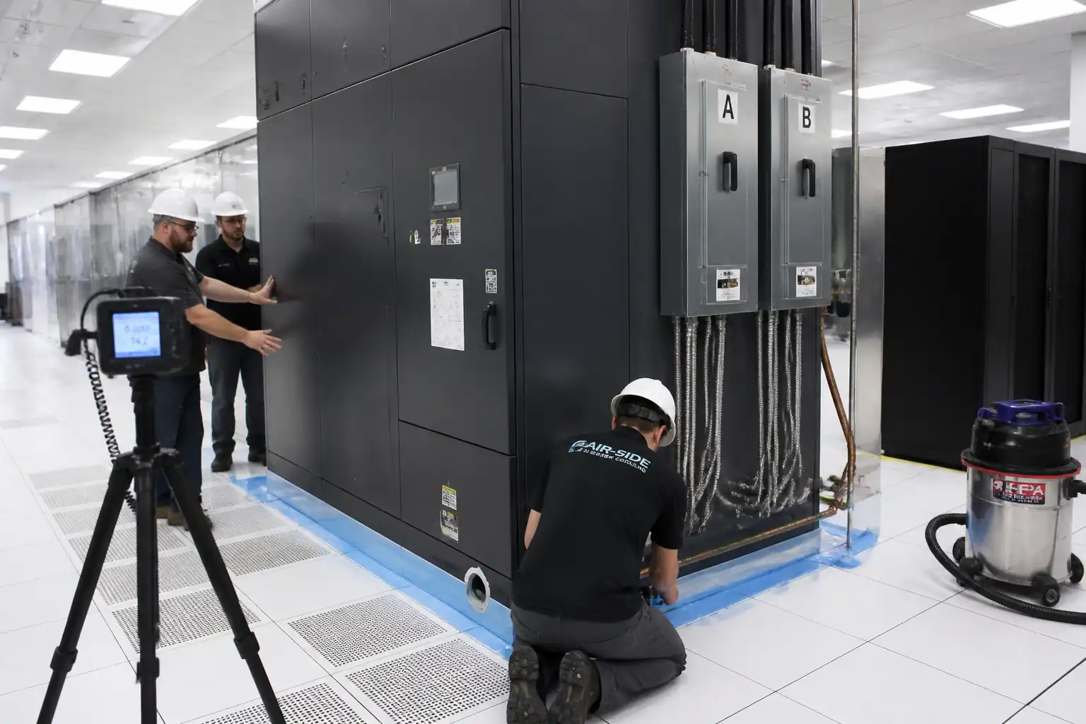
| Underfloor discharge sealing | Smoke-pencil and DP check around base/grommets | No visible smoke; DP within ±10% design; leakage <5% flow [Verify] | Sealing checklist | |
| Humidification water line hydrostatic test | Pressurize to 1.5× operating (min 6 bar) for 2 h | No pressure loss/leaks; gauges calibrated | Pressure test certificate | |
| Backflow prevention device install | Check EN 1717 device type/orientation and isolation valves | Correct device/class; accessible for maintenance | Inspection record | |
| Condensate drain test | Water flow test ≥5 L; observe trap/priming | No leaks; continuous drainage; trap seal maintained | Drain test sheet | |
| DX system pressure/vacuum/leak (if applicable) | N2 pressure test; vacuum to ≤500 microns; EN 14624 leak scan | Stable pressure 24 h; vacuum rise <200 microns/30 min; 0 leaks | Refrigerant test report | |
| Electrical termination (A/B) | Visual, lug crimp torque, segregation, labeling | Per IEC 60364 and OEM; correct labels; torque per datasheet | Termination checklist | |
| Electrical verification tests | IR, PE continuity, polarity, phase rotation, protective device test | IR ≥1 MΩ (or OEM); PE <0.5 Ω; correct polarity/rotation; devices operate | Electrical test report | |
| Controls/BMS point-to-point | I/O verification, alarms, network communication | 100% points proven; alarms reach BMS | P2P sheets | |
| Pre-functional OEM checks | OEM start-up checklist | All items pass; safeties verified | OEM checklist | |
| Start-up sequence (A then B) | Sequential energization; observe inrush; no backfeed/interlock operation | Smooth start; no trips; no cross-feed | Start-up log | |
| Airflow and plenum DP verification | Measure airflow with balometer; plenum DP points | Airflow within ±10%; DP within ±10% design | TAB report | |
| Thermal/humidity performance | Supply temperature/RH stabilization; humidifier function | Supply 18–27°C; dew point 5.5–15°C; stable RH per design [Verify] | Performance report | |
| ISO 14644 particle counts | Particle counter at ≥3 locations/unit zone | Meets specified class (typ. ISO 8 thresholds) | Particle count log | |
| As-built and O&M submission | Document completeness check | Approved by Engineer/Client | Handover dossier |
This table is a read-only public reference. Download the PDF or Excel version, or customize this ITP to edit it for your project.
Frequently asked questions
Related method statement
This Inspection and Test Plan is associated with the Method Statement: Installation of Computer Room Air Conditioning (CRAC) Units in Data Centers method statement, which describes the step-by-step construction sequence, resources, materials, equipment, safety controls, and environmental controls for this activity.
View the Method Statement: Installation of Computer Room Air Conditioning (CRAC) Units in Data Centers method statement →Continue with related inspection, method statement, article, and checklist resources.