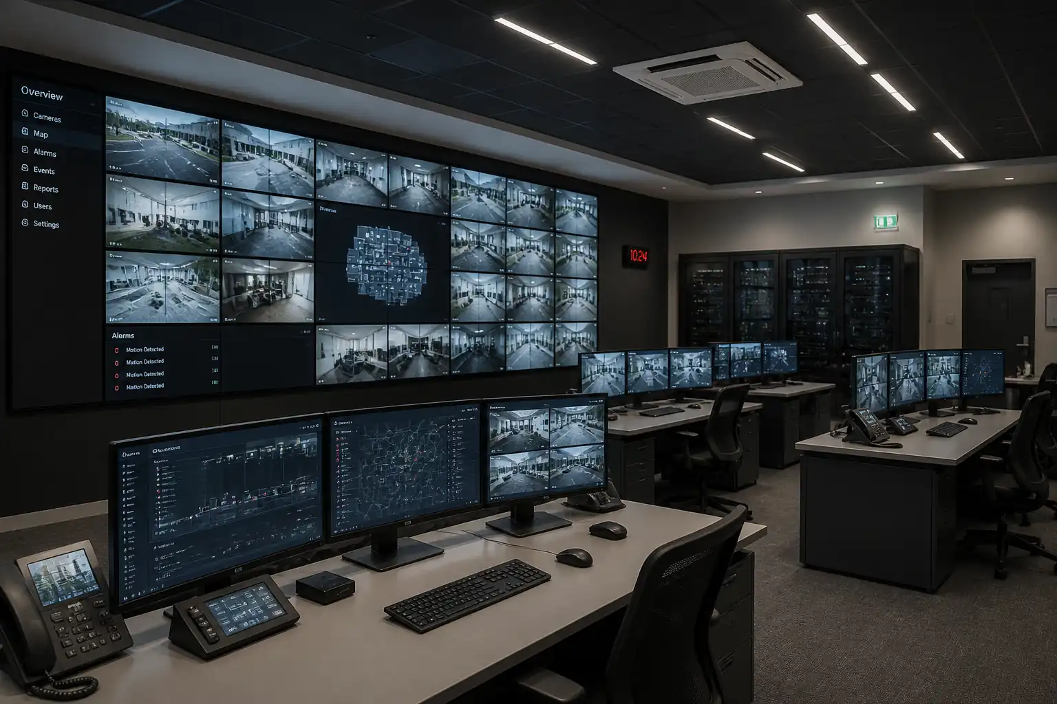

Inspection and Test Plan for Method Statement – Security Command Centre Fit-Out and Commissioning
AI-assisted inspection and test plan connected to a method statement, with PDF and Excel export.
More than a static template
Unlike a downloadable Word or PDF template, this ITP is an AI-assisted editable starting point directly connected to its method statement. Every inspection activity, hold point, and acceptance criterion is structured and ready to adapt to your project.
- AI-assisted customization — Tailor inspection activities and acceptance criteria to your specific project scope.
- Linked method statement — This ITP is connected to the corresponding method statement describing the work sequence.
- Multiple export formats — Download as a formatted PDF or editable Excel spreadsheet.
- Editable starting point, not a final document — Review and verify all content against your project specifications and standards before use.
What you can customize
When you save this ITP to your account, every inspection row becomes editable. You can add, remove, or modify:
- Inspection activity — Description of what is being inspected.
- Inspection type — Hold point (H), Witness point (W), Review (R), or Monitor (M).
- Responsibility — Contractor, subcontractor, engineer, or client.
- Frequency — How often the inspection occurs.
- Acceptance criteria — Referenced standard or specification requirement.
- Records — Forms, test reports, or checklists required as evidence.
Why this ITP is used
To provide verifiable checkpoints ensuring installations meet design intent, standards, and manufacturer requirements before handover.
Who uses this inspection and test plan
Contractor supervisors, QA/QC, specialist vendors, commissioning managers, and the Client/Engineer for witness/hold points.
When this ITP is prepared and submitted
From initial site setup through installation, testing, calibration, and SAT prior to handover.
Who receives or approves this ITP
Client/Engineer for review, approval, and witnessing of hold points.
Inspection scope
Containment, racks, power, UPS, cabling, lighting, video wall alignment, calibration, ergonomics, environmental stability, and system integration.
Typical hold, witness, and review points
Set-out verification (Hold), anchor installation (Hold), video wall alignment (Hold), display calibration (Witness), UPS start-up (Witness), endurance SAT (Witness).
Typical inspection records
IRs, electrical test sheets, cabling certification, calibration reports, UPS logs, lighting survey, environmental logs, SAT report, as-builts and O&M manuals.
Important approval note
This ITP is an AI-assisted editable starting point, not a pre-approved document. Before use on any project, all inspection activities, hold points, and acceptance criteria must be reviewed and approved by the relevant parties (superintendent, principal contractor, or client representative) in accordance with your contract and project quality plan.
Always verify acceptance criteria against your applicable drawings, specifications, and regulatory requirements. Hold points must be confirmed with the relevant authority before work proceeds past that point.
Inspection and test plan
| Activity | Inspection / Test | Acceptance Criteria | Responsibility | Record |
|---|---|---|---|---|
| Room and substrate verification | Dimensions, substrate integrity, services scan review | Room dims within tolerance; substrate sound; no clashes with services | CM / QA-QC | IR, survey report |
| Containment installation | Support spacing, level, bonding | Spacing ≤1.2–1.5 m [Verify]; level ±5 mm/5 m; bonding ≤0.1 Ω | MEP Supv. / QA-QC | IR, continuity record |
| Rack installation & bonding | Plumb and bonding test | Verticality ±2 mm/2 m; bonding ≤0.1 Ω to earth | MEP Supv. / QA-QC | IR, bonding test |
| Video wall support anchors | Torque check; sample pull-out tests | Torque within OEM tolerance; pull-out ≥1.5× design load [Verify] | AV Lead / QA-QC | Anchor log, pull-test report |
| Power rough-in and PDUs | Continuity, IR, polarity, EFLI | IEC 60364 compliant; IR ≥1 MΩ @500 VDC; correct polarity | MEP Supv. / QA-QC | Electrical test sheets |
| UPS installation and start-up | Vendor pre-energization checks and start-up | IEC 62040 conformance; alarms clear; correct comms | UPS Vendor / MEP Supv. | UPS start-up checklist |
| Cabling installation | Routing, bend radius, segregation | Cu ≥4×OD; Fiber ≥10×OD; power/data separation maintained | Cabling Lead / QA-QC | Install QA sheets, photos |
| Terminations and labeling | Pinout/fiber end-face inspection | Correct pinout; clean end-faces; labeling per scheme | Cabling Lead / QA-QC | Termination logs |
| Copper certification | Permanent Link to Class EA (ISO/IEC 11801) | Pass all parameters (NEXT/PSNEXT, RL, ACR-F, TCL as applicable) | Cabling Lead / QA-QC | DSX reports (PDF/native) |
| Fiber testing | LSPM and OTDR | IL ≤0.35 dB/conn; ≤0.1 dB/splice; ORL ≥26 dB [Verify] | Cabling Lead / QA-QC | Test reports |
| Lighting verification | Illuminance survey; UGR assessment | 300–500 lx task; UGR ≤19; uniformity ≥0.6 [Verify] | MEP Supv. / QA-QC | Lighting report |
| Video wall alignment | Planarity/seam checks | Flatness ±2 mm; seam uniformity ±0.3 mm [Verify] | AV Lead / QA-QC | Alignment report |
| Display calibration | Colorimeter measurements | D65 6500K±200K; 120–160 cd/m²; gamma 2.2±0.1; ΔEavg ≤2 (max ≤3); uniformity ≤10% | AV Lead / QA-QC / Client Rep | Calibration reports |
| Sightline and ergonomic checks | Viewing angle and character height assessment | Vertical ≤35°; horizontal ≤30°; H ≥ distance/200 | AV Lead / Ergonomist / Client Rep | Sightline report |
| Systems integration tests | Routing, control, latency, failover | 100% sources routable; control reliable; failover per design | AV Lead / IT / QA-QC | Integration test sheets |
| UPS autonomy and transfer | Battery autonomy; transfer to/from bypass | Autonomy ≥ specified; no unintended interruption; alarms correct | UPS Vendor / MEP Supv. | UPS reports, logs |
| Environmental conditioning verification | Temp/RH logging; noise level check | 20–24°C; 40–60% RH; NR/NC 30–35 [Verify] | Cx Manager / MEP Supv. | Env. log report |
| Endurance run / SAT | 8–24 h continuous operation; failover scenarios | No critical faults; error logs within acceptable thresholds | Cx Manager / Client Rep | SAT report, sign-off |
This table is a read-only public reference. Download the PDF or Excel version, or customize this ITP to edit it for your project.
Frequently asked questions
Related method statement
This Inspection and Test Plan is associated with the Method Statement – Security Command Centre Fit-Out and Commissioning method statement, which describes the step-by-step construction sequence, resources, materials, equipment, safety controls, and environmental controls for this activity.
View the Method Statement – Security Command Centre Fit-Out and Commissioning method statement →