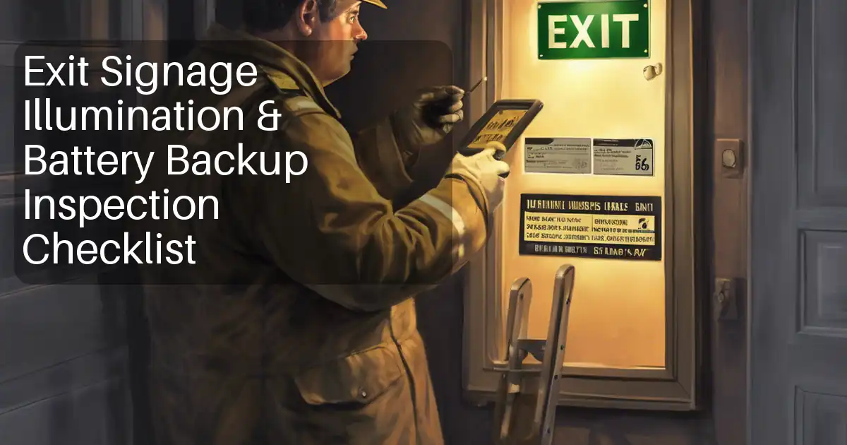
Inspection and Test Plan for Method Statement – Installation and Commissioning of Exit Signs (Wall/Ceiling Mounted)
AI-assisted inspection and test plan connected to a method statement, with PDF and Excel export.
More than a static template
Unlike a downloadable Word or PDF template, this ITP is an AI-assisted editable starting point directly connected to its method statement. Every inspection activity, hold point, and acceptance criterion is structured and ready to adapt to your project.
- AI-assisted customization — Tailor inspection activities and acceptance criteria to your specific project scope.
- Linked method statement — This ITP is connected to the corresponding method statement describing the work sequence.
- Multiple export formats — Download as a formatted PDF or editable Excel spreadsheet.
- Editable starting point, not a final document — Review and verify all content against your project specifications and standards before use.
What you can customize
When you save this ITP to your account, every inspection row becomes editable. You can add, remove, or modify:
- Inspection activity — Description of what is being inspected.
- Inspection type — Hold point (H), Witness point (W), Review (R), or Monitor (M).
- Responsibility — Contractor, subcontractor, engineer, or client.
- Frequency — How often the inspection occurs.
- Acceptance criteria — Referenced standard or specification requirement.
- Records — Forms, test reports, or checklists required as evidence.
Why this ITP is used
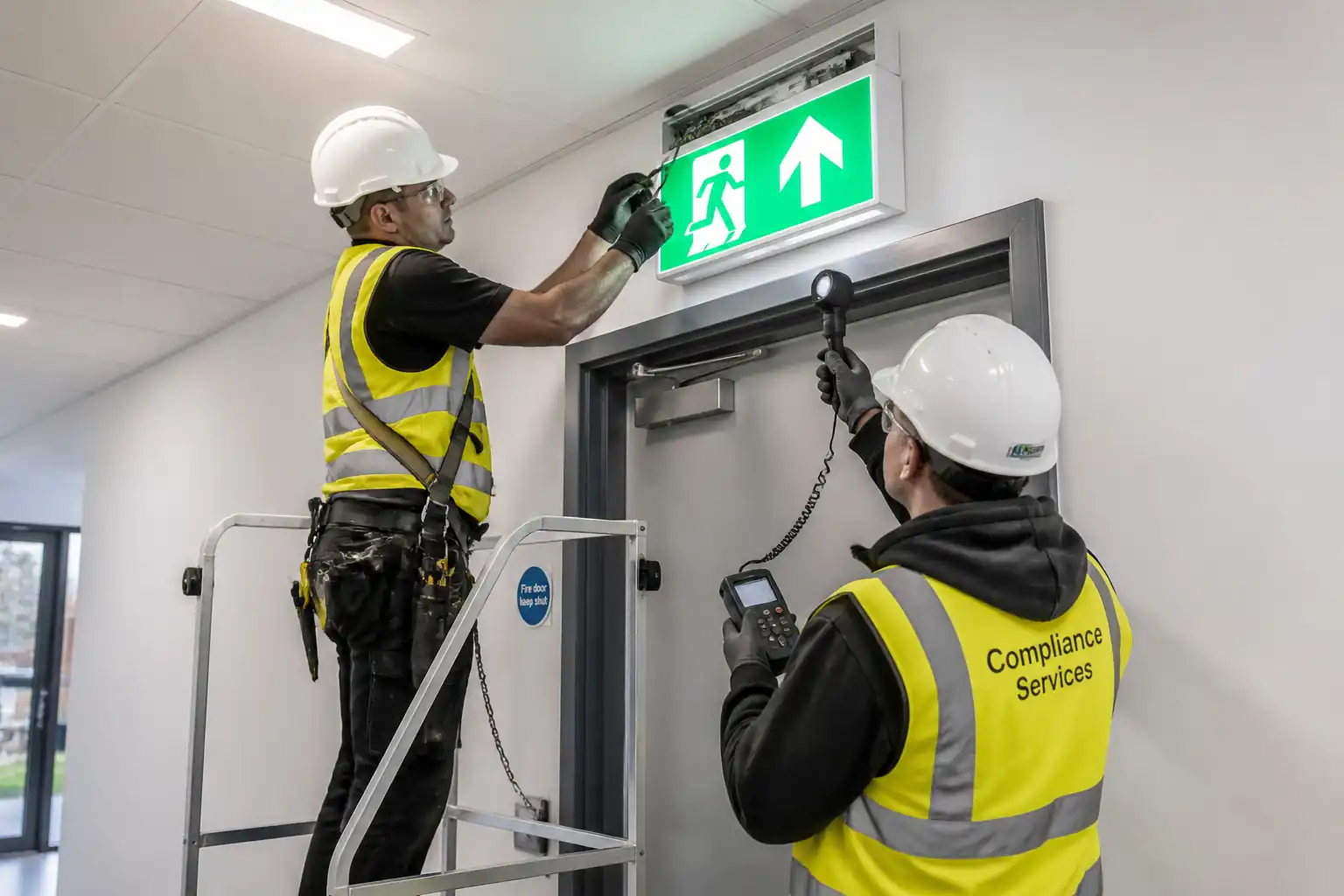
To verify compliance of installed exit signs with design, safety codes, and performance benchmarks before handover.
Who uses this inspection and test plan
Contractor QA/QC, Electrical Supervisor, HSE, and the Engineer/Authority Having Jurisdiction.
When this ITP is prepared and submitted
Applied throughout installation and commissioning, with key hold/witness points during orientation and luminance testing.
Who receives or approves this ITP
Engineer/Resident Engineer or Authority Having Jurisdiction.
Inspection scope
Materials verification, set-out, fixings, wiring, electrical tests, orientation, luminance/visibility, battery autonomy, firestopping, documentation.
Typical hold, witness, and review points
HOLD: Legend orientation; Luminance/visibility. WITNESS: Electrical tests, battery autonomy. REVIEW: PTW, documentation.
Typical inspection records
Material certificates, IRs, test sheets (IR, continuity, luminance, autonomy), calibration certs, firestop logs, as-builts.
Important approval note
This ITP is an AI-assisted editable starting point, not a pre-approved document. Before use on any project, all inspection activities, hold points, and acceptance criteria must be reviewed and approved by the relevant parties (superintendent, principal contractor, or client representative) in accordance with your contract and project quality plan.
Always verify acceptance criteria against your applicable drawings, specifications, and regulatory requirements. Hold points must be confirmed with the relevant authority before work proceeds past that point.
Inspection and test plan
| Activity | Inspection / Test | Acceptance Criteria | Responsibility | Record |
|---|---|---|---|---|
| Material receipt – signs, legends, batteries, anchors | Verify models, certificates (UL/CE), quantities, damage check | Matches approved submittals; certification valid | QA/QC (C), ER (R) | MIR, certificates |
| Set-out and locations | Check positions/heights vs drawings | Correct location; clear sightline | SE/QAQC (C), ER (W) | IR with marked-up plan |
| Permit to Work and Isolation | PTW/LOTO documents review; zero-voltage check | Valid permits; zero-energy verified | Supervisor/HSE (C), ER (R) | PTW, LOTO log |
| Substrate/anchors and fixings | Anchor type/size/spacing; sample pull test 10–20% @1.5× SWL [Verify] | No slip/failure; torque per MI | QA/QC (W), ER (W) | Anchor test sheet |
| Mounting alignment | Level/plumb check | ±2 mm or ≤1° | QA/QC (C), ER (W) | IR/Checklist |
| Wiring and terminations | Polarity, CPC continuity, torque check | Correct terminations; secure; labels fitted | QA/QC (W) | Electrical checklist |
| Electrical tests (pre-functional) | Insulation resistance ≥1 MΩ @500V DC [Verify]; continuity <1 Ω (typ.) | Meets code/MI | QA/QC (W), ER (W) | Test sheets |
| Legend/pictogram orientation | Orientation vs egress plan; ISO 7010/NFPA text compliance | Correct arrow/face direction; compliant color/contrast | QA/QC (H), ER (H) | HOLD release on IR |
| Luminance level and visibility | Measure legend luminance and uniformity; visibility from designated points | Lmin ≥2 cd/m²; Lmax/Lmin ≤10; visible without obstruction [Verify per BS EN 1838/project] | QA/QC (H), ER (W/H) | Luminance report, photos |
| Battery autonomy (90-min) test | Discharge duration and end-voltage check | Maintains illumination for ≥90 min; end voltage within MI | QA/QC (W), ER (W) | Commissioning sheet |
| Firestopping of penetrations | System and labeling per approval | FRL matches barrier; neat install | QA/QC (W), ER (R) | Firestop log/photos |
| Final documentation and handover | Review O&M, test records, as-builts | Complete; no outstanding NCRs | PM/QAQC (C), ER (R) | Handover dossier |
This table is a read-only public reference. Download the PDF or Excel version, or customize this ITP to edit it for your project.
Frequently asked questions
Related method statement
This Inspection and Test Plan is associated with the Method Statement – Installation and Commissioning of Exit Signs (Wall/Ceiling Mounted) method statement, which describes the step-by-step construction sequence, resources, materials, equipment, safety controls, and environmental controls for this activity.
View the Method Statement – Installation and Commissioning of Exit Signs (Wall/Ceiling Mounted) method statement →Continue with related inspection, method statement, article, and checklist resources.