Install Inclinometer Casings: Depth, Verticality, Baseline
Definition: Install inclinometer casings using this field checklist for geotechnical teams, confirming depth, verticality, baseline reference readings, and protective caps, excluding data interpretation beyond initial setup activities.
- Verify design depth and casing verticality with calibrated tools and survey.
- Capture baseline reference readings at fixed intervals for future comparisons.
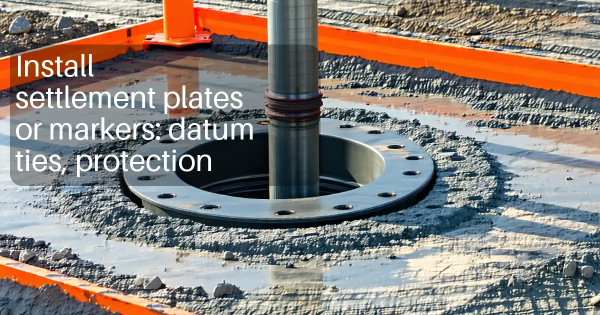
- Protect casing tops with labeled, lockable caps and durable covers.
- Interactive, commentable checklist with export and QR code verification.
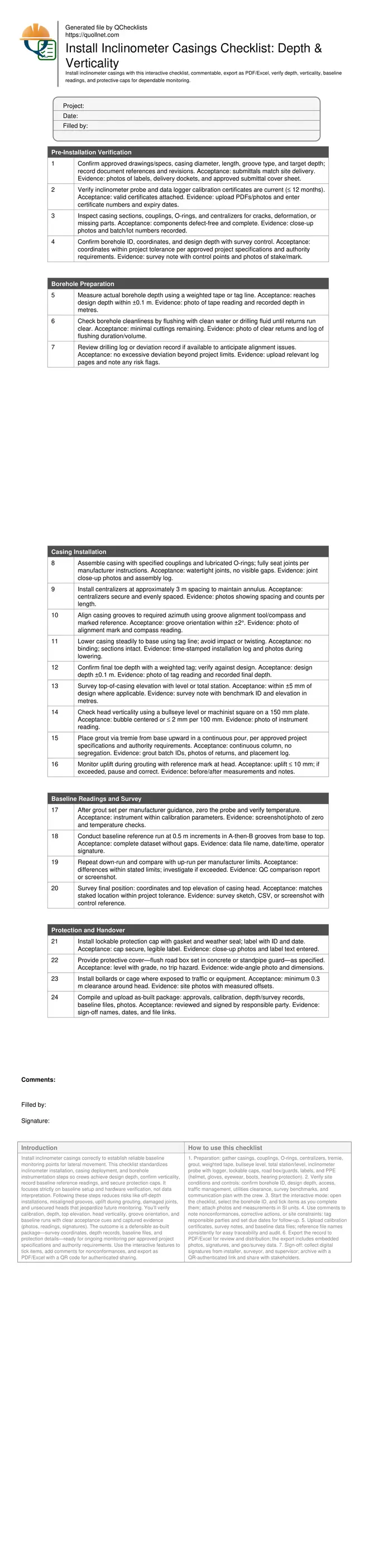
Install inclinometer casings correctly to establish reliable baseline monitoring points for lateral movement. This checklist standardizes inclinometer installation, casing deployment, and borehole instrumentation steps so crews achieve design depth, confirm verticality, record baseline reference readings, and secure protection caps. It focuses strictly on baseline setup and hardware verification, not data interpretation. Following these steps reduces risks like off-depth installations, misaligned grooves, uplift during grouting, damaged joints, and unsecured heads that jeopardize future monitoring. You’ll verify calibration, depth, top elevation, head verticality, groove orientation, and baseline runs with clear acceptance cues and captured evidence (photos, readings, signatures). The outcome is a defensible as-built package—survey coordinates, depth records, baseline files, and protection details—ready for ongoing monitoring per approved project specifications and authority requirements. Use the interactive features to tick items, add comments for nonconformances, and export as PDF/Excel with a QR code for authenticated sharing.
- Fast, repeatable process for inclinometer casing installation that focuses on depth confirmation, head verticality, groove alignment, and baseline reference readings. Crews capture photos, calibration certificates, and survey notes to produce a defensible, audit-ready as-built package for monitoring.
- Clear acceptance criteria and tolerances steer field decisions—design depth within ±0.1 m, head verticality verified at the plate, groove orientation aligned to survey marks, and baseline runs completed per manufacturer limits. Each step requires evidence for traceable quality control.
- Protection measures—lockable caps, labeled IDs, flush road boxes, and barriers—preserve access and integrity for future measurements. Documented handover includes coordinates, elevations, file names, and sign-offs, minimizing rework and safeguarding monitoring continuity across project phases.
- Interactive online checklist with tick, comment, and export features secured by QR code.
Pre-Installation Verification
Borehole Preparation
Casing Installation
Baseline Readings and Survey
Protection and Handover
Scope, Risks, and Acceptance Cues for Inclinometer Casings
This checklist targets baseline installation of vertical inclinometer casings only—confirming depth, verticality at the head, groove orientation, baseline reference readings, and protective measures. It avoids data interpretation and ongoing monitoring analysis. The main risks are off-depth completion, poorly seated joints, misaligned grooves, uplift during grouting, and unsecured or unlabeled heads. Acceptance cues include design depth achieved within ±0.1 m, casing head verticality verified on a reference plate, correctly aligned orthogonal grooves, and complete baseline runs captured with a calibrated probe. Practical field evidence—photos, survey notes, calibration certificates, and signed data logs—forms a traceable quality trail. Following a consistent method reduces rework, protects borehole integrity, and ensures that subsequent monitoring starts from a reliable reference. Use manufacturer instructions alongside approved project specifications and authority requirements to select appropriate couplings, O-rings, centralizers, grout approach, and protection hardware that match site constraints.
- Limit scope to baseline setup; exclude interpretation and trend analysis.
- Achieve design depth within ±0.1 m, evidenced by weighted tape.
- Verify head verticality on a 150 mm plate or bullseye level.
- Align grooves to marked azimuth within ±2° and document.
- Capture complete baseline runs and save source data files.
Methods to Confirm Depth, Verticality, and Alignment
Depth is verified using a weighted tape or tag line before and after lowering the casing, ensuring the toe meets design within tolerance. Head verticality is checked using a machinist square or bullseye level placed on a rigid plate; a centered bubble or ≤ 2 mm per 100 mm plate indicates acceptance. Groove orientation is established with a groove alignment tool and compass against a marked azimuth; aim for ±2°. Survey equipment—automatic level or total station—records top-of-casing elevation and coordinates for as-built documentation. If grouting is specified, place via tremie from the base upward while monitoring for uplift at the head. These field methods are simple, repeatable, and minimize reliance on assumptions. Each verification step should be photographed and paired with measurements recorded in SI units, enabling rapid review and sign-off without ambiguity.
- Use weighted tape to confirm toe depth pre- and post-installation.
- Check head verticality with a bullseye level on a flat plate.
- Set groove azimuth using compass and reference marks.
- Survey top elevation and coordinates against project control.
- Monitor uplift during grouting; limit to ≤ 10 mm.
Baseline Reference Runs and Protection for Long-Term Access
Baseline reference readings enable later comparisons, but this checklist limits itself to collecting the initial dataset only. After grout set, zero and verify the inclinometer probe, then run at 0.5 m intervals in both groove directions. Repeat in the opposite direction and compare runs to ensure differences are within manufacturer limits. Save files with consistent naming conventions and capture screenshots for traceability. Protect the casing with a lockable cap, legible ID, and a cover (road box or standpipe guard) suited to site traffic. Add bollards or a cage when exposed to equipment. Proper protection prevents impact damage, water ingress, and unauthorized access, safeguarding future monitoring. Close with an as-built package containing approvals, coordinates, elevations, photos, calibration certificates, baseline data files, and signatures.
- Complete baseline runs in both groove orientations.
- Save source data files and screenshots with timestamps.
- Install lockable, labeled caps to prevent contamination.
- Use road boxes or guards where vehicles operate.
- Deliver a signed as-built document set.
How to Use This Checklist On Site
- Preparation: gather casings, couplings, O-rings, centralizers, tremie, grout, weighted tape, bullseye level, total station/level, inclinometer probe with logger, lockable caps, road box/guards, labels, and PPE (helmet, gloves, eyewear, boots, hearing protection).
- Verify site conditions and controls: confirm borehole ID, design depth, access, traffic management, utilities clearance, survey benchmarks, and communication plan with the crew.
- Start the interactive mode: open the checklist, select the borehole ID, and tick items as you complete them; attach photos and measurements in SI units.
- Use comments to note nonconformances, corrective actions, or site constraints; tag responsible parties and set due dates for follow-up.
- Upload calibration certificates, survey notes, and baseline data files; reference file names consistently for easy traceability and audit.
- Export the record to PDF/Excel for review and distribution; the export includes embedded photos, signatures, and geo/survey data.
- Sign-off: collect digital signatures from installer, surveyor, and supervisor; archive with a QR-authenticated link and share with stakeholders.
Call to Action
- Start Checklist Tick off tasks, leave comments on items or the whole form, and export your completed report to PDF or Excel—with a built-in QR code for authenticity.
- Download Excel - Inclinometer Casing Installation Inspection
- Download PDF - Inclinometer Casing Installation Inspection
- View Image - Inclinometer Casing Installation Inspection
Cite & Embed
“Inclinometer Casing Installation Inspection by Quollnet”
with a link to
this source page.
FAQ
Question: What tolerances should I use for inclinometer casing depth and head verticality?
Question: When should baseline reference readings be taken after installation?
Question: How do I align the casing grooves correctly for future monitoring?
Question: What protection is recommended for the casing head in traffic areas?
Related Articles
Broader reading and guidance connected to this checklist topic.


Is It Important To Customize Your Qr Code And How To Do It?

Related Checklists
Keep the workflow moving with nearby templates chosen from similar checklist content.