
Method Statement: Exothermic Welding of Earthing and Lightning Protection Connections – Method Statement
AI-assisted method statement with matching ITP, PDF download, and Excel export.
More than a static template
Unlike a downloadable Word or PDF template, this method statement is an AI-assisted editable starting point connected directly to a matching Inspection and Test Plan. Every section is structured, project-adaptable, and ready to export.
- AI-assisted drafting — Customize every section with AI for your specific project scope.
- Linked ITP — A matching inspection and test plan is generated alongside the method statement.
- Multiple export formats — Download as a formatted PDF or editable Excel spreadsheet.
- Editable starting point, not a final document — Review, verify, and adjust all content against your project requirements before use.
Static template vs. Quollnet workflow
| Feature | Static template | Quollnet |
|---|---|---|
| Project-specific content | Manual fill-in required | AI-assisted customization |
| Linked ITP | Separate document, no link | Matching ITP included |
| Export formats | Usually PDF only | PDF and Excel |
| Structured sections | Free-form layout | 13 standardized sections |
| Saved to your account | Local file only | Cloud-saved, reusable |
| Content accuracy | You verify everything | AI-assisted, you still verify |
| Cost | Often free but time-intensive | Free to customize and download |
What you can customize
When you save this method statement to your account, every section becomes editable. The following 13 sections are included:
- Scope — Defines the activity and its boundaries.
- References — Standards, specifications, and drawings.
- Responsibilities — Roles and accountabilities.
- Resources — Labour, plant, and equipment summary.
- Materials — Materials and compliance requirements.
- Equipment — Tools and equipment details.
- Prerequisites — Hold points and pre-conditions.
- Method sequence — Step-by-step construction sequence.
- Safety controls — HSE risk controls and PPE.
- Environmental controls — Environmental mitigation measures.
- QA/QC — Quality inspection and test requirements.
- ITP — Inspection and Test Plan table (has its own page).
- Attachments — Referenced drawings and documentation.
Why this method statement is used
This method statement is used to define and communicate the approved procedure for carrying out method statement: exothermic welding of earthing and lightning protection connections on site. It ensures the work is planned in advance, the correct resources and controls are in place, and all personnel understand responsibilities, sequence, quality requirements, and safety controls before work begins. It aligns site execution with the documented scope and acceptance expectations.
Who uses this method statement
This method statement is used by contractors, site supervisors, project engineers, QA/QC engineers, HSE officers, consultants, and client representatives. It serves as a shared reference for planning, execution, supervision, inspection, and approval of the activity on site.
When it is prepared and submitted
The method statement is prepared before the work activity starts and submitted as part of the pre-construction documentation package for review and approval.
Who reviews or approves it
The method statement is usually submitted to the client representative, consultant, resident engineer, or project management consultant for review and approval before the work commences.
Important approval note
This method statement is an AI-assisted editable starting point, not a pre-approved document. Before use on any project, all content must be reviewed and approved by the relevant parties (superintendent, principal contractor, or client representative) in accordance with your contract and project quality plan.
For example: if your specification requires a departure from a referenced standard, that departure must be documented and approved separately — this method statement will not capture that automatically. Always verify against your applicable drawings, specifications, and regulatory requirements.
Method statement content
Scope
Description
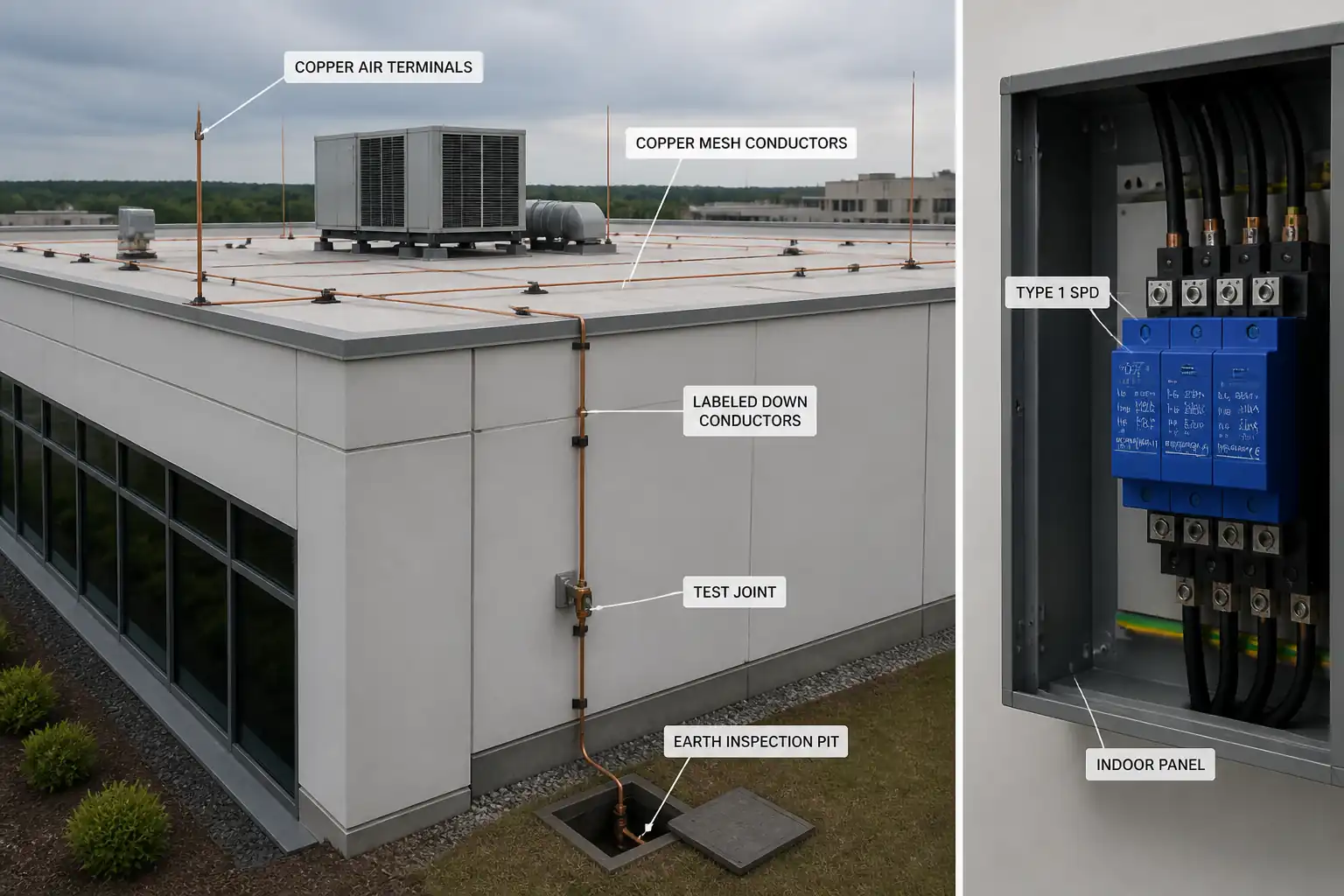
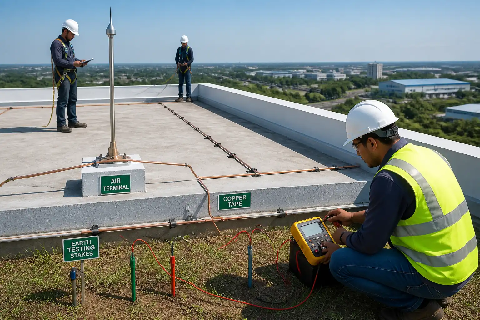
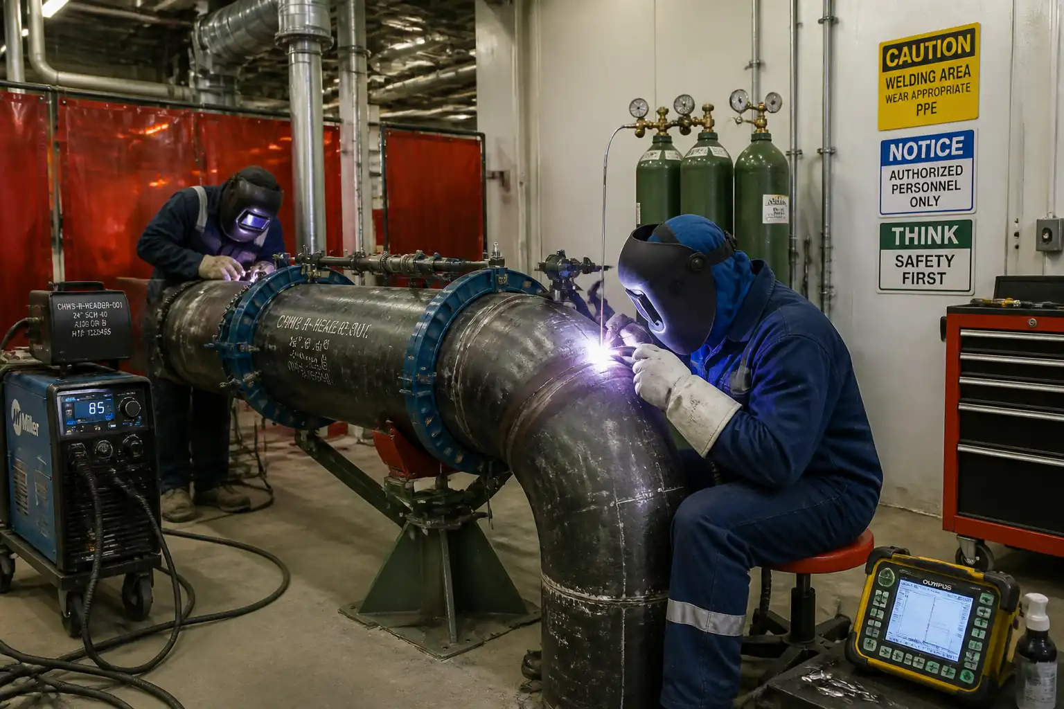
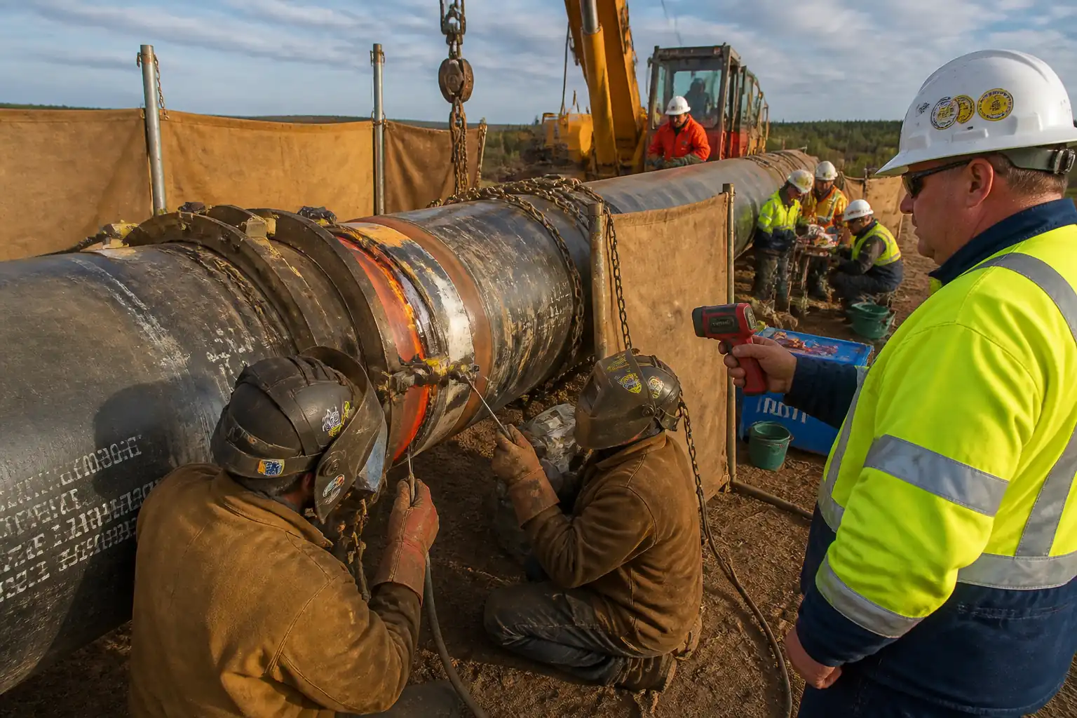
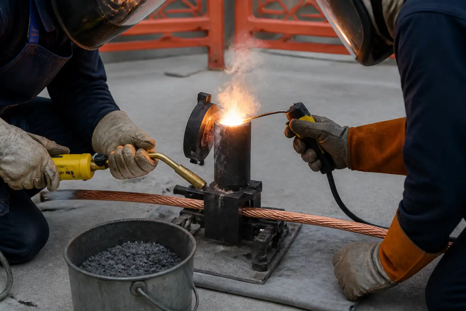
This method covers the materials, equipment, sequence, inspection, and HSE controls for exothermic (thermite) welding of earthing grid conductors, ground rods, and lightning protection bonding connections. The scope includes preparation, welding, post-weld finishing, coating, 100% visual and hammer testing, QA/QC hold-point inspection, and sample pull-testing.
Inclusions
- Cable-to-cable, cable-to-rod, cable-to-strip, and cable-to-structure exothermic welds using approved graphite molds and weld metal charges.
- Mold preheating and conditioning; conductor surface preparation to bright metal.
- Ignition using approved igniters; slag removal; mold maintenance.
- Post-weld verification: visual inspection, hammer test, and electrical resistance sampling.
- Corrosion protection of completed joints (below and above grade) and zinc repair where galvanizing is affected.
- Recording batch numbers, mold IDs, locations, and test results.
Exclusions
- Cadmium, soft solder, brazing, and fusion arc welding of earthing conductors.
- Aluminum conductor welding.
- Permanent connections other than exothermic unless stated in project specs.
Constraints
- Do not weld in rain, standing water, or on wet/moist conductors or molds.
- Do not quench molds or joints with water.
- Follow manufacturer’s specific mold/charge selection and ignition procedure. [Verify per project specifications]
References
| Document Type | Reference / Number | Revision | Notes |
|---|---|---|---|
| Standard | IEC 62305 (Lightning Protection) [Verify applicability per project] | ||
| Standard | IEC 62561 series (Lightning protection system components) – particularly Parts 1, 2, 7 [Verify applicability] | ||
| Standard | IEEE Std 837 (Qualifying permanent connections for substation grounding) – guidance for performance criteria | ||
| Standard | IEEE Std 80 (Guide for Safety in AC Substation Grounding) – earthing design and joint performance concepts | ||
| Standard | UL 467 (Grounding and Bonding Equipment) – product conformity where applicable | ||
| Standard | ASTM A780 (Repair of Damaged and Uncoated Areas of Hot-Dip Galvanized Coatings) – for post-weld zinc repair | ||
| Standard | ASTM D740 – Standard Practice for Storage and Handling of Solvents [or equivalent, Verify] | Use IPA or approved degreaser per MSDS | |
| Manufacturer | Manufacturer instructions (e.g., nVent ERICO CADWELD, Furse, Harger) – mold selection, charge sizing, ignition, safety | Mandatory to follow the specific product procedure | |
| Project Spec | Project Specifications, Drawings, and Approved Material Submittals [Verify per project specifications] |
Responsibilities
| Role | Responsibility | Name / Party |
|---|---|---|
| PM | Project Manager | Contractor |
| Engineer | Site/Field Engineer | Contractor |
| QA/QC | QA/QC Engineer | Contractor |
| HSE | HSE Officer | Contractor |
| Technician | Certified Exothermic Welding Technician | Contractor |
| Foreman | Electrical Foreman / General Foreman | Contractor |
| Client/Engineer | Client/Engineer | Employer/Engineer |
| Lab | Independent Laboratory | Independent |
Resources
| Resource Type | Description | Quantity | Remarks |
|---|---|---|---|
| Manpower | 1 Certified Exothermic Welding Technician, 1 Assistant/Helper | 2 persons/team | |
| Training | Manufacturer training for technician within last 24 months | ||
| Supervision | 1 Foreman per up to 2 welding teams | 1:2 |
Materials
| Material | Specification / Grade | Quantity | Remarks |
|---|---|---|---|
| Weld metal powder | Per manufacturer data; IEEE 837 guidance | As per BOQ | |
| Per manufacturer | As required | ||
| Per manufacturer | As required | ||
| ASTM/ISO compliant where applicable [Verify] | Consumable | ||
| IEC 62561-7 guidance (material compatibility) [Verify] | As required | ||
| ASTM A780 | As required |
Equipment
| Equipment | Capacity / Type | Quantity | Inspection Required |
|---|---|---|---|
| Igniter | 1 set/team | Yes | |
| Torch | 1/team | Yes | |
| Thermometer | 1/crew | Yes | |
| DLRO | 1 | Yes | |
| Pull tester | Up to project-required kN | As required | Yes |
| Various | Set/team | ||
| Extinguishers | Per workfront | Yes | |
| Each worker | Yes |
Prerequisites
- Approved Method Statement and ITP, risk assessment, and permits (Hot Work; Confined Space if applicable). [Verify per project HSE plan and local regulations]
- Approved materials and manufacturer’s instructions available at point of use; material MIRs closed.
- Drawings/locations confirmed and set out; connection types and mold/powder charts selected.
- Weather and site conditions suitable: no rain; welding area dry; wind shields/canopy provided if necessary.
- Equipment inspected and calibrated: DLRO, pull-tester, IR thermometer (if used). Calibration certificates current.
- Technicians trained and certified by the exothermic system manufacturer.
- Nearby services isolated/protected; housekeeping and fire watch arranged; spill kits and Class D extinguisher available.
- Mock-up or first-off sample completed if required by contract; acceptance recorded.
- Batch numbers of weld metal, disks, and mold IDs registered in weld log sheets.
Method Sequence
| Step | Activity | Description | Responsibility | Inspection / Hold Point |
|---|---|---|---|---|
| 1 | Workfront preparation | Barricade 1.5 m radius around weld point; deploy fire watch and fire controls; sign PTW at site | Foreman/HSE | HSE check |
| 2 | Verify components | Confirm conductor materials/sizes and joint type; select matching mold and weld metal charge per manufacturer chart | Technician/Engineer | QA check |
| 3 | Inspect mold | Check mold cavity, vents, handles, and seals for cracks or wear; clean graphite surfaces | Technician | Self-check |
| 4 | Dry and preheat mold | Using torch, warm mold to drive off moisture (target 100–150°C). Avoid overheating (>300°C). | Technician | Supervisor check |
| 5 | Prepare conductors | Cut square; remove oxides to bright metal using stainless brush/emery; degrease with IPA; ensure dry | Technician | QA surveillance |
| 6 | Position conductors in mold | Place conductors fully seated and centered; secure with clamps; ensure gap/overlap per mold design | Technician | Supervisor check |
| 7 | Install disk and charge | Insert steel/ceramic disk; pour weld metal into crucible; add starting powder as per manufacturer | Technician | QA surveillance |
| 8 | Hold point – pre-ignition check | Final check of setup, exclusion zone, PPE, and ignition leads; announce ignition | QA/QC + Client/Engineer (Hold) | Hold point |
| 9 | Ignition | Ignite using approved igniter at arm’s length; do not lean over mold; step back immediately | Technician | HSE watch |
| 10 | Cooling | Allow to cool undisturbed (typ. ≥60–90 s) before opening; do not quench | Technician | Self-check |
| 11 | Open mold & remove slag | Open mold carefully; remove slag from crucible and surface using scraper; avoid damaging joint | Technician | Supervisor check |
| 12 | Visual inspection (100%) | Check for full fill, proper fusion, smooth surface, no cracks/porosity/cold shuts; conductor alignment verified | QA/QC + Technician | 100% visual |
| 13 | Hammer test (100%) | After cooling to ambient, strike joint with 0.5–1 kg hammer (≈5 moderate blows from ~150 mm) | QA/QC | Functional |
| 14 | Electrical resistance (sampling) | Measure DC resistance with DLRO across joint vs. equivalent length of parent conductor | QA/QC | Test (sampling) |
| 15 | Hold point – weld quality inspection | Client/Engineer witness of visual and hammer test results and acceptance | QA/QC + Client/Engineer (Hold) | Hold point |
| 16 | Pull-test (sampling) | Perform pull-test on representative samples or mock-ups with proper grips/fixtures | QA/QC / Third-party | Witness |
| 17 | Post-weld dressing | Brush joint; remove spatter/loose material; ensure dry and clean prior to coating | Technician | Supervisor check |
| 18 | Zinc repair (if steel galvanized affected) | Apply zinc-rich repair per ASTM A780 to exposed steel; allow cure | Technician | QA/QC |
| 19 | Joint coating | Apply approved petrolatum/bituminous system (below grade) or UV-resistant coating (above grade) per manufacturer | Technician | QA/QC |
| 20 | Documentation | Record location, joint type, conductor sizes, mold ID, batch numbers, inspection results, and testers’ calibration refs | QA/QC | Document review |
Health, Safety, and Environment – Safety Controls
Task-Specific Hazards and Controls
1) Hazard: Molten metal ejection and high-temperature reaction
- Likely consequence: Severe burns, eye injury, fire
- Engineering/procedural control: 1.5 m exclusion zone; use correct mold/clamp; never look into mold; pre-dry mold; announce ignition; step back immediately
- Required PPE: FR clothing, full face shield over safety goggles, leather gauntlet gloves, safety boots
- Collective preventive measure: Fire watch with Class D extinguisher and dry sand; heat-resistant mat under work area
- Inspection/permit/supervision: Hot Work Permit; HSE supervisor present for first-off and high-risk locations [Verify per project HSE plan and local regulations]
2) Hazard: Moisture in mold or conductor causing violent reaction
- Likely consequence: Spattering/molten metal blowout
- Engineering/procedural control: Preheat mold to remove moisture; verify dryness; keep powders sealed until use; use canopy in damp conditions
- Required PPE: As above
- Collective preventive measure: Dry storage box for powders and molds; weather shields
- Inspection/permit/supervision: Supervisor check of preheat; QA sign-off at hold point
3) Hazard: Fumes and combustion products in confined/poorly ventilated spaces
- Likely consequence: Respiratory irritation, exposure to metal oxides
- Engineering/procedural control: Prefer outdoor welding; if confined, provide forced ventilation; limit personnel
- Required PPE: Respirator with P100/combined cartridge if ventilation inadequate [Verify]
- Collective preventive measure: Gas monitoring if applicable; ventilation fans
- Inspection/permit/supervision: Confined Space Permit; atmospheric testing; standby attendant
4) Hazard: Open flame from torch use
- Likely consequence: Fire, burns, gas leak ignition
- Engineering/procedural control: Leak test torch and hoses; flashback arrestor; maintain clear area free of combustibles; keep cylinder upright and secured
- Required PPE: FR gloves, eye/face protection
- Collective preventive measure: Fire blanket/spark containment
- Inspection/permit/supervision: Hot Work Permit; daily equipment inspection
5) Hazard: Working near energized systems/stray currents
- Likely consequence: Electric shock, arcing, damage to equipment
- Engineering/procedural control: De-energize and lockout/tagout where feasible; maintain separation from live parts; verify isolation for lightning down conductors as applicable
- Required PPE: Electrical-rated gloves as required; insulated tools where applicable
- Collective preventive measure: LOTO boards; barriers and signage
- Inspection/permit/supervision: LOTO permit; supervisor verification
6) Hazard: Manual handling of molds, rods, and equipment
- Likely consequence: Strains, hand injuries
- Engineering/procedural control: Team lifts; use rod clamps/handles; keep grips dry
- Required PPE: Cut-resistant gloves under gauntlets when handling raw conductors
- Collective preventive measure: Mechanical aids where possible
- Inspection/permit/supervision: Manual handling training
7) Hazard: Ignition misfire or delayed reaction
- Likely consequence: Unexpected ignition causing injury
- Engineering/procedural control: Maintain wait time after failed ignition (≥2 min) before approaching; then follow manufacturer’s misfire procedure
- Required PPE: Full PPE maintained until declared safe
- Collective preventive measure: Exclusion until cleared by supervisor
- Inspection/permit/supervision: Supervisor to control re-try per manufacturer guidance
8) Hazard: Damage to galvanizing and subsequent corrosion
- Likely consequence: Accelerated corrosion/failure of bond
- Engineering/procedural control: Use correct mold for steel; limit heat; promptly apply zinc repair and coating per ASTM A780
- Required PPE: As applicable for coatings (gloves/respirator)
- Collective preventive measure: Coating station with spill control
- Inspection/permit/supervision: QA inspection of coating thickness/coverage
9) Hazard: Fire from improper slag disposal
- Likely consequence: Secondary fire, burns
- Engineering/procedural control: Collect hot slag in metal container; allow to cool; never dispose in general waste while hot
- Required PPE: Heat-resistant gloves, face shield
- Collective preventive measure: Designated metal slag bins
- Inspection/permit/supervision: HSE checks during and after works
10) Hazard: Eye injury from hammer test
- Likely consequence: Flying particles
- Engineering/procedural control: Use proper mass hammer; controlled blows; ensure bystanders out of line of fire
- Required PPE: Safety goggles and face shield
- Collective preventive measure: Exclusion zone maintained during testing
- Inspection/permit/supervision: Supervisor oversight
[All controls to be verified per project HSE plan and local regulations]
Environmental Controls
- Slag and spent starting powder: Collect in labeled metal containers; allow to cool; dispose per MSDS and local waste regulations. Do not dump on soil or into drainage.
- Solvent use (IPA/degreasers): Use minimal quantities; store in closed containers with secondary containment; manage wipes as contaminated waste.
- Noise and nuisance: Minimal; maintain exclusion zone and communication during ignition countdown to avoid startle hazards.
- Air quality: Use outdoors or provide local ventilation in enclosed areas; avoid prolonged exposure to fumes.
- Soil and groundwater protection: Place heat-resistant mat under work point to catch spatter; prevent coating drips; use drip trays for zinc repair paint/primers.
- Fire prevention: Maintain Class D extinguisher and dry sand; prohibit water application to reaction or powders.
- Material storage: Keep exothermic powders dry in sealed containers with desiccant; store away from oxidizers and ignition sources; segregate from incompatible materials per MSDS.
- Post-works housekeeping: Remove all debris, slag, spent disks, and temporary barriers; reinstate surfaces; verify no hot items remain before demobilization.
Quality Assurance / Quality Control
Controls
- Materials: Verify product approvals and compatibility; record batch/lot numbers for weld metal, disks, and mold IDs.
- Equipment: Calibration of DLRO and pull-tester current; igniter functional; torch leak-tested.
- Personnel: Manufacturer-certified technician; toolbox talk before shift.
- Mock-up: Perform first-off weld for each joint type and conductor size; obtain QA and Engineer approval.
Inspection and Testing
- 100% visual inspection per manufacturer and IEEE 837 concepts: full fill, proper wetting, no porosity/cracks, conductor alignment, no voids/cold shuts.
- 100% hammer test: 0.5–1 kg hammer, approx. 5 controlled blows; no cracking or loosening.
- Electrical resistance sampling (typ. 10% per type/day) using DLRO; acceptance: joint resistance ≤ equivalent length of parent conductor [Verify per project].
- Pull-test sampling: Typical 1 per 20 joints per joint-type per day or 5% minimum [Verify]. Acceptance: no failure at specified load (project to define). Typical benchmark: 60–80% of the minimum tensile strength of the smallest connected conductor or ≥5–10 kN for common LV earthing sizes [Verify per project specifications].
Nonconformance and Repair
- Defective joints (visual/hammer/resistance failure): Cut out entire joint with minimum 150 mm clearance from defect, re-prepare conductors, and re-weld with new mold/charge; record as NCR and corrective action.
- Molds showing erosion, cracks, or poor seating: Remove from service; replace.
Records and Traceability
- Weld log: Date/time, location, joint type, conductor sizes, mold ID, charge size, batch/lot numbers, technician ID.
- Inspection reports: Visual/hammer sign-offs, photos, DLRO readings, pull-test certificates, coating inspections.
- Calibration certificates: DLRO, pull-tester, IR thermometer (if used) current and filed.
Hold/Witness Points
- Hold: Pre-ignition setup check (first-off per type and as requested).
- Hold: Post-weld quality inspection (visual and hammer test).
- Witness: Pull-test (sampling or qualification).
Attachments
- Manufacturer’s data sheets and instructions (mold/charge selection charts, ignition procedures, safety data)
- Material approvals (MIRs) and batch/lot traceability log template
- Weld log sheet (location, type, sizes, mold ID, batch nos., operator)
- Visual/hammer test checklist
- DLRO test log sheet template
- Pull-test procedure and report template; calibration certificates
- Hot Work Permit and Confined Space Permit templates
- Risk Assessment/Job Hazard Analysis (JHA)
- Coating system data sheets and application procedure
- ASTM A780 zinc repair procedure sheet
- As-built redlines showing weld locations
This content is a read-only public reference. Download or customize to get an editable version.
ITP preview
The first inspection activities from the linked ITP for Method Statement: Exothermic Welding of Earthing and Lightning Protection Connections:
| Activity | Inspection / Test | Acceptance Criteria | Responsibility | Record |
|---|---|---|---|---|
| Materials receipt – weld metal, disks, molds | Visual, document check | Correct types/sizes; undamaged; dry; certificates available | QA/QC, Client/Engineer (Witness) | MIR, Material approval, Batch log |
| Technician competency | Certificate check | Valid manufacturer training/certification [Verify] | QA/QC | Training record |
| Workfront readiness and PTW | Permit verification | Hot Work Permit active; controls in place | HSE, Foreman, Client/Engineer (Witness) | PTW, HSE checklist |
Showing 3 of 12 inspection activities. View full ITP →
Related Inspection and Test Plan
An Inspection and Test Plan (ITP) is available for Method Statement: Exothermic Welding of Earthing and Lightning Protection Connections. The ITP defines the inspection activities, acceptance criteria, hold and witness points, responsible parties, and records required to verify the work described in this method statement.
View the Method Statement: Exothermic Welding of Earthing and Lightning Protection Connections ITP →Frequently asked questions
Continue with related Quollnet resources connected to this method statement.