
Method Statement – Lightning Protection System (LPS) Installation, Bonding, Surge Protection, and Testing – Method Statement
AI-assisted method statement with matching ITP, PDF download, and Excel export.
More than a static template
Unlike a downloadable Word or PDF template, this method statement is an AI-assisted editable starting point connected directly to a matching Inspection and Test Plan. Every section is structured, project-adaptable, and ready to export.
- AI-assisted drafting — Customize every section with AI for your specific project scope.
- Linked ITP — A matching inspection and test plan is generated alongside the method statement.
- Multiple export formats — Download as a formatted PDF or editable Excel spreadsheet.
- Editable starting point, not a final document — Review, verify, and adjust all content against your project requirements before use.
Static template vs. Quollnet workflow
| Feature | Static template | Quollnet |
|---|---|---|
| Project-specific content | Manual fill-in required | AI-assisted customization |
| Linked ITP | Separate document, no link | Matching ITP included |
| Export formats | Usually PDF only | PDF and Excel |
| Structured sections | Free-form layout | 13 standardized sections |
| Saved to your account | Local file only | Cloud-saved, reusable |
| Content accuracy | You verify everything | AI-assisted, you still verify |
| Cost | Often free but time-intensive | Free to customize and download |
What you can customize
When you save this method statement to your account, every section becomes editable. The following 13 sections are included:
- Scope — Defines the activity and its boundaries.
- References — Standards, specifications, and drawings.
- Responsibilities — Roles and accountabilities.
- Resources — Labour, plant, and equipment summary.
- Materials — Materials and compliance requirements.
- Equipment — Tools and equipment details.
- Prerequisites — Hold points and pre-conditions.
- Method sequence — Step-by-step construction sequence.
- Safety controls — HSE risk controls and PPE.
- Environmental controls — Environmental mitigation measures.
- QA/QC — Quality inspection and test requirements.
- ITP — Inspection and Test Plan table (has its own page).
- Attachments — Referenced drawings and documentation.
Why this method statement is used
This method statement is used to define and communicate the approved procedure for carrying out method statement – lightning protection system (lps) installation, bonding, surge protection, and testing on site. It ensures the work is planned in advance, the correct resources and controls are in place, and all personnel understand responsibilities, sequence, quality requirements, and safety controls before work begins. It aligns site execution with the documented scope and acceptance expectations.
Who uses this method statement
This method statement is used by contractors, site supervisors, project engineers, QA/QC engineers, HSE officers, consultants, and client representatives. It serves as a shared reference for planning, execution, supervision, inspection, and approval of the activity on site.
When it is prepared and submitted
The method statement is prepared before the work activity starts and submitted as part of the pre-construction documentation package for review and approval.
Who reviews or approves it
The method statement is usually submitted to the client representative, consultant, resident engineer, or project management consultant for review and approval before the work commences.
Important approval note
This method statement is an AI-assisted editable starting point, not a pre-approved document. Before use on any project, all content must be reviewed and approved by the relevant parties (superintendent, principal contractor, or client representative) in accordance with your contract and project quality plan.
For example: if your specification requires a departure from a referenced standard, that departure must be documented and approved separately — this method statement will not capture that automatically. Always verify against your applicable drawings, specifications, and regulatory requirements.
Method statement content
Scope
Work Included
- Supply, installation, and testing of the complete Lightning Protection System (LPS) for .
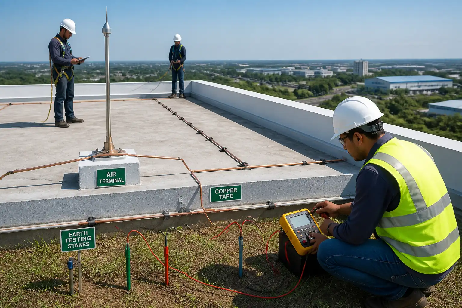
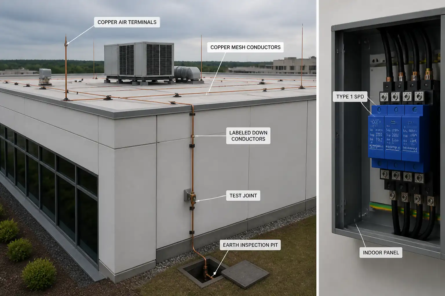
- Air-termination system (rods/masts/mesh), down conductors, test points, and earth termination network (earth ring, rods, plates as applicable).
- Main earthing bar (MEB) and equipotential bonding to building structural steel, rebar (where designed), and metallic services (water, gas, HVAC, telecom, PV frames, etc.).
- Surge Protective Devices (SPD): Type 1 at service entrance when external LPS is present, Type 2 at distribution boards, Type 3 at sensitive equipment, including coordination and earthing connections.
- Labels, marking, as-built drawings, and O&M documentation.
- Testing and commissioning: continuity, earth resistance (3-point fall-of-potential), clamp-on verification (where applicable), separation distance verification, and final connectivity/impedance checks.
- Hold points: (1) Pre-closure inspection of test links and down-conductor routing; (2) Final connectivity and impedance test prior to system handover.
Exclusions
- Structural assessments other than LPS fixings loads.
- Civil works beyond earth pits, minor trenches, and backfilling for LPS.
- HV utility surge protection outside project boundary.
Assumptions
- Approved LPS risk assessment and class (I–IV) available with design drawings.
- Earthing system tie-in points identified and permitted for bonding.
- Power shutdowns/permits for SPD installation scheduled.
Objectives
- Provide a compliant, safe, and maintainable LPS achieving the specified protection level and target earthing resistance.
- Deliver traceable QA/QC records and ITP-compliant inspections.
References
| Document Type | Reference / Number | Revision | Notes |
|---|---|---|---|
| Standard | IEC/BS EN 62305-1/2/3/4 | Adopt either IEC or BS EN per jurisdiction; ensure consistency. | |
| Standard | IEC/EN 62561 (relevant parts) | -1 General, -2 Conductors/earth electrodes, -4 Clamps, -7 Earthing enhancing compounds | |
| Standard | IEC/EN 61643-11 and 61643-12 | UL 1449 where applicable [Verify] | |
| Standard | IEC 60364-5-54 and IEC 60364-6 | Continuity testing methods and insulation verification | |
| Standard | IEEE Std 81 | Alternative national method may apply [Verify] | |
| Standard | ISO 1461 | For supports and brackets where galvanized steel is used | |
| Standard | ASTM B3/B8/B170 | Use equivalent local standards if required | |
| Standard | NFPA 780 | Use only if mandated by contract [Verify] |
Responsibilities
| Role | Responsibility | Name / Party |
|---|---|---|
| PM | Ensure compliance and close-out | Contractor |
| SE | Daily checks, RFIs, redlines | Contractor |
| QA/QC | Witness/hold management, NCRs | Contractor |
| HSE | Compliance with HSE plan and legal requirements | Contractor |
| Specialist | Workmanship to standards and manufacturer instructions | Subcontractor |
| Electrician | LOTO and electrical safety | Contractor |
| Surveyor | Issue utility avoidance report | Specialist |
| 3rd Party | Provide calibrated results | Independent |
| Vendor Rep | Confirm correct product application | Supplier |
Resources
| Resource Type | Description | Quantity | Remarks |
|---|---|---|---|
| Manpower | LPS and electrical supervision | As per program | |
| Manpower | Air terminals, conductors, joints | 4–8 nos. [Verify] | |
| Manpower | SPD and bonding terminations | 2–4 nos. [Verify] | |
| Manpower | Utility scanning and set-out | 1 crew [Verify] | |
| Manpower/Access | Access for roof and façade | As required |
Materials
| Material | Specification / Grade | Quantity | Remarks |
|---|---|---|---|
| Cu/Al | ≥99% Cu; if Al, avoid contact with concrete | As per design | |
| EC-grade copper | Conductivity ≥97% IACS [Verify] | As per design | |
| Bronze/SS | SS A4 (316) in coastal zones [Verify] | As per design | |
| Cu-bonded steel | Copper thickness ≥250 µm [Verify] | As per design | |
| Polymer/Concrete | UV and chemical resistant | As per design | |
| Graphite mold + charge | Per vendor | As required | |
| Tinned copper | ≥50×6 mm bar [Verify] | As per design | |
| SPD | Uc e.g., 275 V AC for TN-S [Verify] | As per design | |
| SS/galv/UV polymer | SS A4 in coastal zones [Verify] | As required |
Equipment
| Equipment | Capacity / Type | Quantity | Inspection Required |
|---|---|---|---|
| DLRO/continuity tester | 0–2 Ω | 1–2 | |
| Earth tester | 0–2000 Ω | 1 | |
| Clamp meter | 0.01–1200 Ω | 1 | |
| GPR + locator | 1 set | ||
| Exothermic kit | As required | ||
| Boom/scissor | As required | ||
| Hammer drill | As required |
Prerequisites
Approvals and Documents
- Approved LPS design drawings, risk assessment, and defined protection class (I–IV).
- Confirm calculation of separation distance s per IEC/BS EN 62305-3; issue marked-up routes showing areas requiring bonding vs. isolation.
- Approved material submittals (LPS components to IEC/EN 62561; SPDs to IEC/EN 61643-11).
- ITP approved with identified hold and witness points.
Site Readiness
- Utility scans and permits for excavation; mark no-dig zones and safe corridors.
- Access equipment inspected; edge protection/scaffolding certified.
- Power isolation plan and LOTO for SPD installation; shutdown windows agreed.
Calibration and Competence
- Test instruments within calibration; operators trained and authorized.
- Exothermic welding operatives trained; hot work permits prepared.
Materials Logistics
- Components delivered with COC/MTC; store dry and segregate dissimilar metals to prevent galvanic corrosion.
Coordination
- Interfaces with structural steel contractor, MEP services, façade/roofing contractor agreed; penetration and waterproofing details approved.
Method Sequence
| Step | Activity | Description | Responsibility | Inspection / Hold Point |
|---|---|---|---|---|
| 1 | Pre-start briefing and permits | Toolbox talk on LPS works, hot works, work-at-height, excavation; issue PTWs and LOTO as needed | HSE Manager / Site Engineer | Permit verification |
| 2 | Set-out and separation distance confirmation | Mark air terminals, conductor routes, test joints, MEB, earth pits. Confirm separation distance s zones from design. | Site Engineer / LPS Specialist | Layout check |
| 3 | Utility detection and trial holes | GPR and cable locator scan; hand-dig trial holes for earth pits/trenches | Surveyor / Civil crew | Excavation permit |
| 4 | Install earth ring and electrodes | Lay earth ring ~0.6–0.8 m deep and ≥0.5 m from foundation [Verify]. Drive 3 m rods at corners/equidistant spacing 6–10 m [Verify]. | LPS Specialist | Trench and rod depth check |
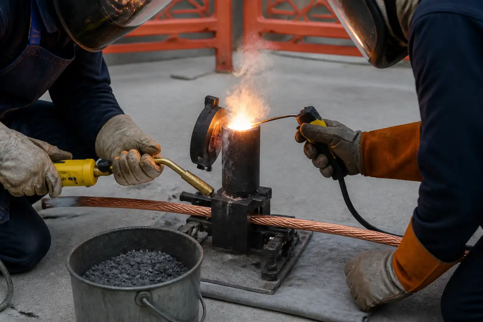
| 5 | Exothermic welds and mechanical joints | Execute Cu–Cu and Cu–rod joints; clean surfaces; observe drying and preheat as needed; protect post-weld | LPS Specialist | Hot work inspection |
| 6 | Install earth inspection pits | Place chambers flush with grade; ensure drainage; label electrodes and test links | Civil/LPS crew | Level and compaction |
| 7 | Initial earth resistance test | 3-point fall-of-potential test with C and P stakes; minimum 52%–62% spacing steps | QA/QC with Tester | Test setup review |
| 8 | Install main earthing bar (MEB) and test links | Mount MEB on insulated stand-offs; provide removable links for test; tag all connections | Electrician | Fixing and torque |
| 9 | Bond to structural steel/rebar (where designed) | Bond via approved clamps or welded pads; avoid compromising fireproofing; protect against corrosion | LPS Specialist | Joint inspection |
| 10 | Rooftop conductor holders and fixings | Install holders at spacing ≤1.0 m vertical/≤1.5 m horizontal [Benchmark – Verify]; seal penetrations | LPS Specialist | Fixings inspection |
| 11 | Install air-termination system | Rods/masts/mesh per design using rolling sphere/mesh method; maintain coverage at edges and rooftop equipment | LPS Specialist | Coverage check |
| 12 | Install down conductors and test points | Route via shortest paths; avoid sharp bends (radius ≥8× conductor thickness); install test joints 1.5–1.8 m above FFL | LPS Specialist | Routing inspection |
| 13 | Equipotential bonding of services | Bond metallic services near entry; respect insulating joints on gas; use bimetallic clamps if required | Electrician | Service isolation and bond check |
| 14 | Install SPDs (Type 1/2/3) | Fit at MSB/DBs/equipment; leads as short and straight as possible (L+N+PE total ≤0.5 m where practical) | Electrician | LOTO and wiring check |
| 15 | Labelling and identification | Label test points, MEB, SPDs, earth pits; route markers on concealed runs | Site Engineer | Label QA |
| 16 | Pre-closure inspection (Hold Point) | Verify all terminations, joints, and test links are accessible; confirm separation distances or bonding at crossings | QA/QC + Engineer/Client | Joint-by-joint review |
| 17 | Final continuity and impedance checks (Hold Point) | Measure continuity for each down-conductor path from air terminal to earth via test link; verify low-impedance paths | QA/QC + Third-Party (if specified) | Instrument calibration check |
| 18 | Final earth resistance and loop verification | Repeat 3-point test for overall LPS; clamp-on verification where parallel paths exist | Tester/QA/QC | Test review |
| 19 | As-builts, O&M, handover | Compile test results, certificates, product data, maintenance plan, and redline drawings | Project Manager/QA | Document review |
Health and Safety Controls
Key Task-Specific Hazards and Controls
1) Work at height on roof/edges
- Hazard: Falls from height; dropped objects.
- Likely consequence: Fatality/serious injury; damage below.
- Engineering/procedural control: Collective edge protection or certified lifelines; MEWP with harness and short lanyard; toe-boards; tool lanyards; exclusion zones.
- Required PPE: Full body harness, double lanyard, helmet with chinstrap, gloves, non-slip footwear, eye protection.
- Collective preventive measure: Guardrails/scaffolds; debris nets where applicable.
- Inspection/permit/supervision: Work-at-height permit; MEWP daily checks; competent operator; weekly scaffold inspections [Verify per project HSE plan and local regulations].
2) Exothermic welding (hot works)
- Hazard: Burns, fire, fumes, hot metal splatter.
- Likely consequence: Burns, ignition of roofing materials.
- Engineering/procedural control: Hot work permit; fire blankets; 5 m hot work zone; fire watch 60 minutes post-weld; store charges dry; follow vendor procedures.
- Required PPE: Flame-resistant gloves, face shield, safety glasses, long-sleeve FR clothing, hearing protection.
- Collective preventive measure: Fire extinguishers (CO2/dry powder), spark containment, non-combustible mats.
- Inspection/permit/supervision: Gas test if in enclosed areas; hot work permit with sign-off; dedicated fire watch.
3) Underground utility strike during earth electrode installation
- Hazard: Contact with live cables/pipes.
- Likely consequence: Electrocution, explosion, flooding.
- Engineering/procedural control: GPR and cable locator scan; hand-dig/trial holes; no mechanical driving within 1 m of suspected utility; depth controls.
- Required PPE: Dielectric gloves when required, insulated tools, eye protection, safety boots.
- Collective preventive measure: Marked exclusion zones; standby first aider.
- Inspection/permit/supervision: Excavation permit; supervision by Site Engineer; as-built utility drawings on site.
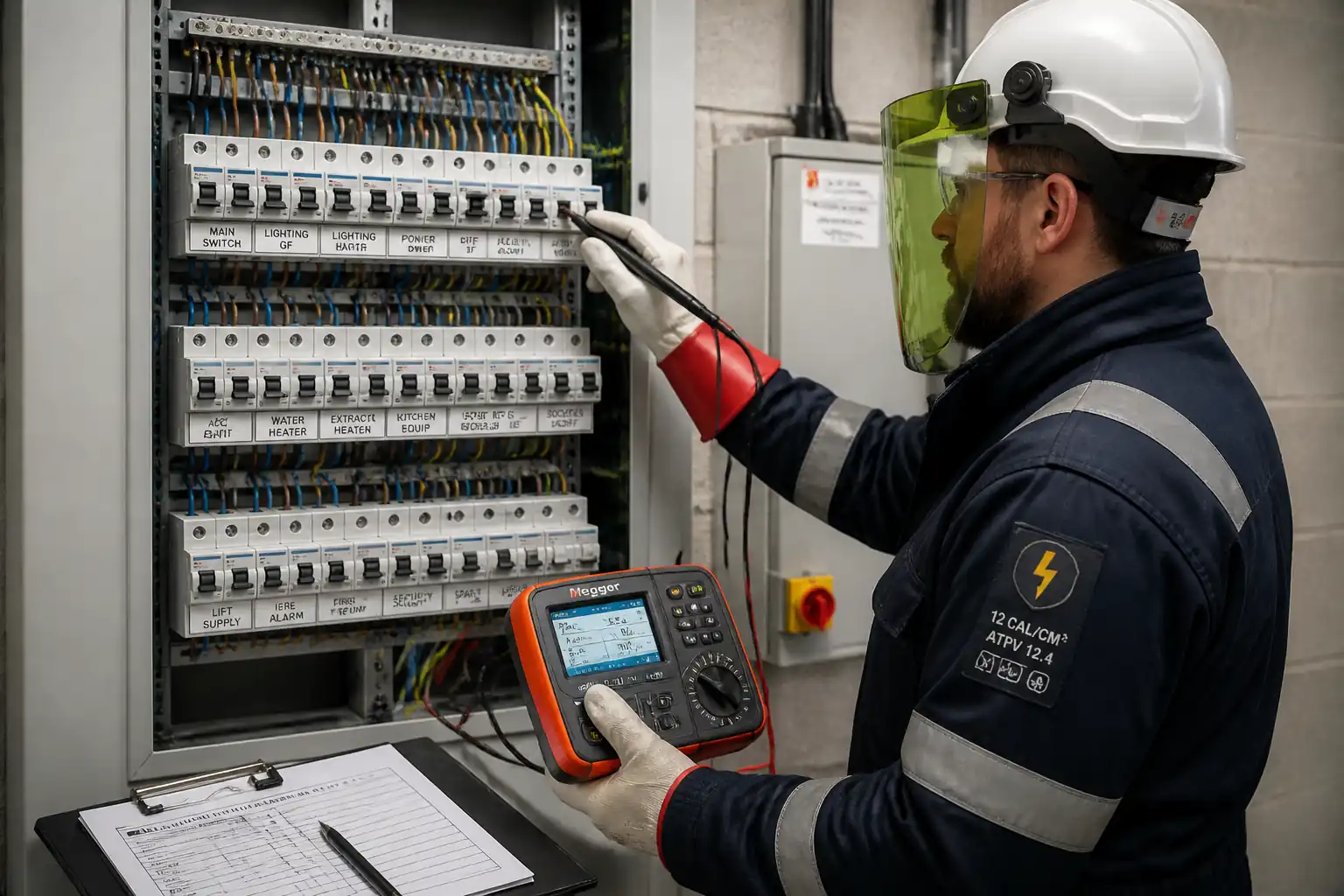
4) Electrical work (SPD installation)
- Hazard: Electric shock/arc flash.
- Likely consequence: Burns, cardiac arrest.
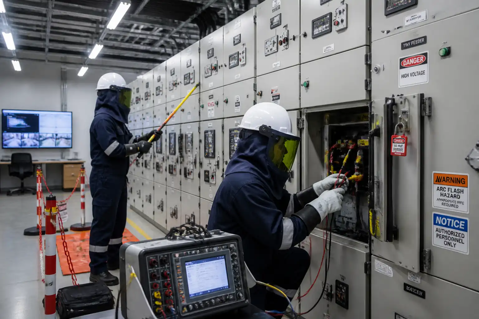
- Engineering/procedural control: LOTO; verify absence of voltage; insulated tools; barriers; correct PPE category.
- Required PPE: Arc-rated clothing (as per arc study [Verify]), voltage-rated gloves, face shield, safety glasses.
- Collective preventive measure: Lock boxes; warning signage; restricted access.
- Inspection/permit/supervision: Electrical PTW; competent electrician; pre-energization checks.
5) Manual handling and anchor drilling
- Hazard: Musculoskeletal strain, dust/silica exposure, noise.
- Likely consequence: Injury, respiratory irritation, hearing loss.
- Engineering/procedural control: Use carts/hoists; two-person lifts for reels; dust extraction and wet drilling where feasible; HEPA vacuums; select low-vibration tools.
- Required PPE: Cut-resistant gloves, FFP2/3 respirator, ear defenders, safety glasses.
- Collective preventive measure: Noise barriers where practical; rotation to limit vibration exposure.
- Inspection/permit/supervision: HAVS monitoring; drilling method statement compliance.
6) Weather and lightning risk
- Hazard: Working on roofs during storms; wind lifting MEWP.
- Likely consequence: Falls; equipment instability.
- Engineering/procedural control: Suspend roof works when thunderstorms forecast or wind > manufacturer limits; use anemometer.
- Required PPE: Weather-appropriate; high-traction footwear.
- Collective preventive measure: Secure materials; tie-downs.
- Inspection/permit/supervision: Supervisor to monitor weather alerts; stop-work authority.
7) Confined/poorly ventilated spaces (basements near MEB)
- Hazard: Low oxygen/fumes during hot works.
- Likely consequence: Asphyxiation/fire.
- Engineering/procedural control: Ventilation; gas monitoring; avoid hot works where possible.
- Required PPE: Gas detector, FR PPE as needed.
- Collective preventive measure: Extraction fans; standby person.
- Inspection/permit/supervision: Confined space permit if criteria met [Verify].
8) Corrosion and galvanic reaction
- Hazard: Dissimilar metal contact in damp zones.
- Likely consequence: Premature failure.
- Engineering/procedural control: Use bimetallic connectors; isolate with dielectric barriers; follow material compatibility schedule.
- Required PPE: Standard site PPE.
- Collective preventive measure: Design review and approvals.
- Inspection/permit/supervision: QA/QC material verification prior to install.
Environmental Controls
Environmental Aspects and Controls
- Soil disturbance and runoff
- Impact: Sedimentation, erosion.
- Control: Limit trench width; maintain silt fences; backfill and compact same day where possible; reinstate surfaces.
-
Monitoring: Daily inspection, after rain events.
-
Chemical/metal leachate from earthing materials
- Impact: Soil/water contamination.
- Control: Use non-leaching ground enhancement materials where specified; avoid copper sulfate. Store exothermic charges in sealed bins away from drains.
-
Monitoring: Material approvals; MSDS compliance.
-
Noise and dust from drilling
- Impact: Nuisance to neighbors/occupants.
- Control: Wet drilling/dust extraction; schedule noisy works off-peak; use acoustic shrouds where practicable.
-
Monitoring: Spot noise readings; complaints log.
-
Waste management
- Impact: General waste accumulation; metal offcuts.
- Control: Segregate copper/aluminum for recycling; dispose of spent exothermic molds/slag as per MSDS; recycle packaging.
-
Monitoring: Waste transfer notes.
-
Roof membrane integrity
- Impact: Water ingress if penetrations are poorly sealed.
- Control: Approved penetration details; sealants compatible with membrane; water test where required.
-
Monitoring: Inspection with roofing contractor sign-off.
-
Visual/heritage considerations (if applicable)
- Impact: Aesthetic impact of masts/conductors.
- Control: Use color-matched fixings and concealed routes where allowed by design.
- Monitoring: Architect/Engineer approval.
Quality Assurance / Quality Control
QA/QC Plan
- Submittals: Approve all materials (COC/MTC), product data sheets, and samples. Confirm standards listed match contract.
- Traceability: Batch numbers for SPDs and exothermic charges recorded; weld/joint log with location photos.
- Workmanship checks: 100% visual inspection of all joints and fixings. Sample torque verification of mechanical terminations (10% or min. 3 per type [Verify]). Anchor pull-out tests per vendor/consultant requirement (≥1.5× design load [Verify]).
- Testing regime:
1) Initial earth resistance after electrode installation.
2) Continuity of each LPS path after routing and bonding.
3) Final continuity and impedance verification at hold point prior to closing test links.
4) Final overall earth resistance.
5) SPD inspection: ratings, wiring polarity, lead length, OCPD/back-up, status/remote contact. - Acceptance criteria (benchmarks – verify per project):
- Earth resistance: ≤10 Ω per electrode typical; overall ≤1–5 Ω if specified by design/soil enhancement.
- Joint resistance: ≤0.1 Ω at mechanical/exothermic joints (or demonstrably negligible vs. conductor length).
- Continuity: Each down conductor path continuous from air terminal to earth; measured resistance consistent with calculated value for length and CSA.
- Coverage: Air-termination geometry satisfies design class using rolling sphere/mesh method.
- SPDs: Type and ratings per schedule; total lead length minimized ≤0.5 m where practicable; correct OCPD/back-up fuses.
- Calibration: All instruments with valid certificates; copies in dossier.
- Records: ITRs, test sheets, photos, as-built drawings, vendor O&M, training records.
- Nonconformance: NCR raised for any deviation; corrective action verified; retest documented.
- Handover: Provide maintenance plan including inspection frequency (visual annually; comprehensive every 2–4 years, after strikes/major works [Verify]).
Attachments
- Approved LPS design drawings and risk assessment sheets.
- Manufacturer data sheets and certificates of conformity (conductors, clamps, electrodes, SPDs, MEB).
- Calculations for separation distance s and air-termination coverage (rolling sphere/mesh/angle method).
- Method statements for hot works, MEWP/scaffolding, and anchor installation.
- Permits to Work: Hot Work, Work at Height, Electrical PTW/LOTO, Excavation PTW.
- Calibration certificates for continuity meters, earth testers, clamp-on testers.
- Inspection/Test Records (ITRs): earth resistance, continuity/impedance, anchor pull-out, SPD installation checklists.
- As-built drawings with cable routes, test points, earth pit locations, and labeling schedules.
- Operation & Maintenance manual, recommended inspection intervals, and warranty documents.
This content is a read-only public reference. Download or customize to get an editable version.
ITP preview
The first inspection activities from the linked ITP for Method Statement – Lightning Protection System (LPS) Installation, Bonding, Surge Protection, and Testing:
| Activity | Inspection / Test | Acceptance Criteria | Responsibility | Record |
|---|---|---|---|---|
| Material receiving and verification | Check standards compliance (IEC/EN 62561, 61643-11); dimensions; finish | Materials match approved submittals; no damage/corrosion | QA/QC + Engineer | Material inspection report |
| Set-out and separation distance check | Measure offsets and proximity to metalwork | Separation distance s achieved or intentional bonding details shown | Site Engineer + LPS Specialist | Setting-out sheet |
| Earth electrodes and ring installation | Depth/spacing; joint methods | Depth 0.6–0.8 m; spacing per design; correct joints | LPS Specialist / QA/QC | ITR – Earthing |
Showing 3 of 13 inspection activities. View full ITP →
Related Inspection and Test Plan
An Inspection and Test Plan (ITP) is available for Method Statement – Lightning Protection System (LPS) Installation, Bonding, Surge Protection, and Testing. The ITP defines the inspection activities, acceptance criteria, hold and witness points, responsible parties, and records required to verify the work described in this method statement.
View the Method Statement – Lightning Protection System (LPS) Installation, Bonding, Surge Protection, and Testing ITP →Frequently asked questions
Continue with related Quollnet resources connected to this method statement.