
Method Statement – Final Electrical Circuit Testing for Building Handover – Method Statement
AI-assisted method statement with matching ITP, PDF download, and Excel export.
More than a static template
Unlike a downloadable Word or PDF template, this method statement is an AI-assisted editable starting point connected directly to a matching Inspection and Test Plan. Every section is structured, project-adaptable, and ready to export.
- AI-assisted drafting — Customize every section with AI for your specific project scope.
- Linked ITP — A matching inspection and test plan is generated alongside the method statement.
- Multiple export formats — Download as a formatted PDF or editable Excel spreadsheet.
- Editable starting point, not a final document — Review, verify, and adjust all content against your project requirements before use.
Static template vs. Quollnet workflow
| Feature | Static template | Quollnet |
|---|---|---|
| Project-specific content | Manual fill-in required | AI-assisted customization |
| Linked ITP | Separate document, no link | Matching ITP included |
| Export formats | Usually PDF only | PDF and Excel |
| Structured sections | Free-form layout | 13 standardized sections |
| Saved to your account | Local file only | Cloud-saved, reusable |
| Content accuracy | You verify everything | AI-assisted, you still verify |
| Cost | Often free but time-intensive | Free to customize and download |
What you can customize
When you save this method statement to your account, every section becomes editable. The following 13 sections are included:
- Scope — Defines the activity and its boundaries.
- References — Standards, specifications, and drawings.
- Responsibilities — Roles and accountabilities.
- Resources — Labour, plant, and equipment summary.
- Materials — Materials and compliance requirements.
- Equipment — Tools and equipment details.
- Prerequisites — Hold points and pre-conditions.
- Method sequence — Step-by-step construction sequence.
- Safety controls — HSE risk controls and PPE.
- Environmental controls — Environmental mitigation measures.
- QA/QC — Quality inspection and test requirements.
- ITP — Inspection and Test Plan table (has its own page).
- Attachments — Referenced drawings and documentation.
Why this method statement is used
This method statement is used to define and communicate the approved procedure for carrying out method statement – final electrical circuit testing for building handover on site. It ensures the work is planned in advance, the correct resources and controls are in place, and all personnel understand responsibilities, sequence, quality requirements, and safety controls before work begins. It aligns site execution with the documented scope and acceptance expectations.
Who uses this method statement
This method statement is used by contractors, site supervisors, project engineers, QA/QC engineers, HSE officers, consultants, and client representatives. It serves as a shared reference for planning, execution, supervision, inspection, and approval of the activity on site.
When it is prepared and submitted
The method statement is prepared before the work activity starts and submitted as part of the pre-construction documentation package for review and approval.
Who reviews or approves it
The method statement is usually submitted to the client representative, consultant, resident engineer, or project management consultant for review and approval before the work commences.
Important approval note
This method statement is an AI-assisted editable starting point, not a pre-approved document. Before use on any project, all content must be reviewed and approved by the relevant parties (superintendent, principal contractor, or client representative) in accordance with your contract and project quality plan.
For example: if your specification requires a departure from a referenced standard, that departure must be documented and approved separately — this method statement will not capture that automatically. Always verify against your applicable drawings, specifications, and regulatory requirements.
Method statement content
Scope
Overview
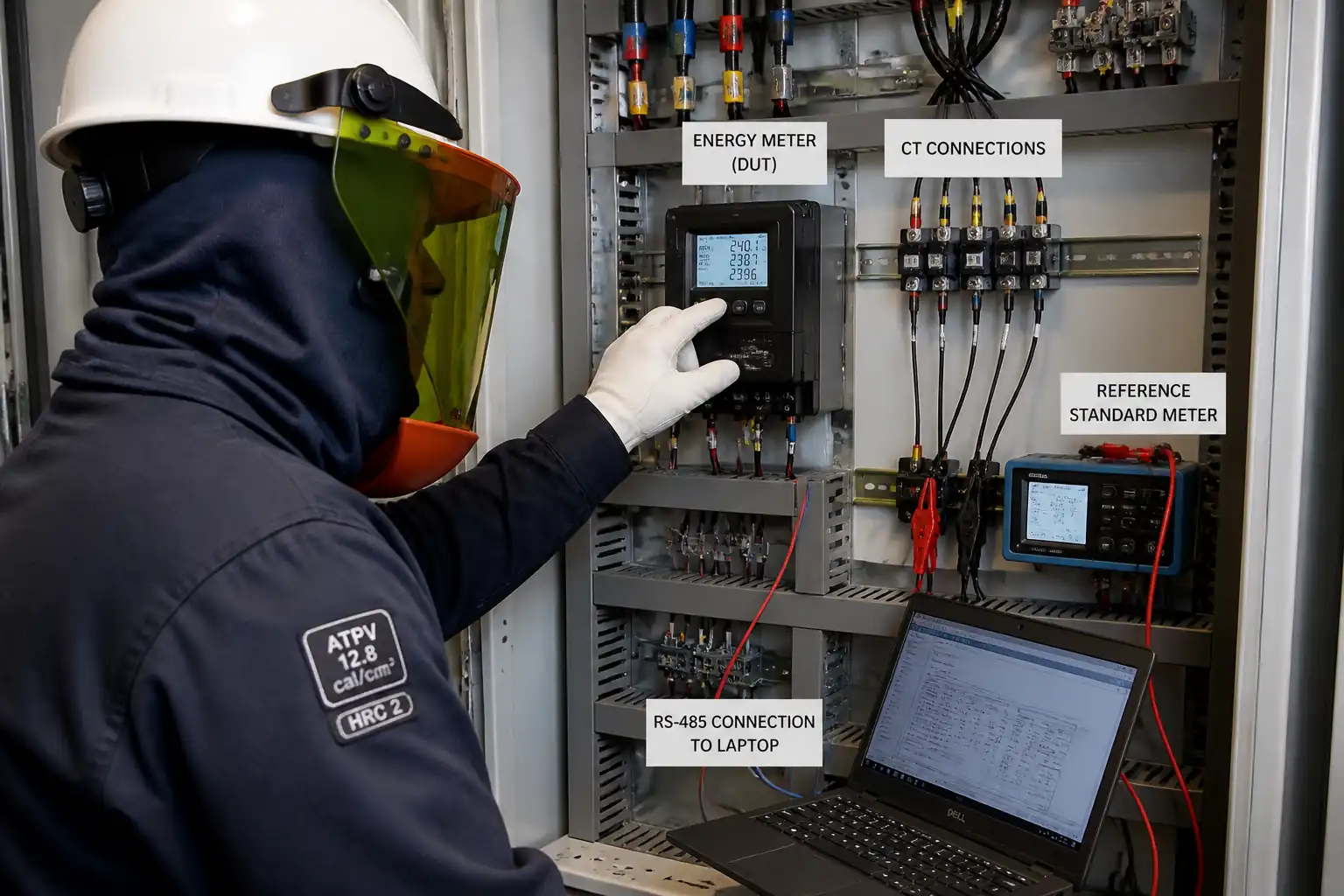
This method statement covers the planning, execution, inspection, testing, and certification of final electrical circuit testing for handover of low-voltage (LV) building installations, typically up to 1 kV AC. The work includes dead and live tests, labelling and documentation, QA/QC witnessing, defect rectification, and final certification.
Included Activities
- Verification of documentation and as-built drawings
- Instrument calibration check and setup
- Isolation/LOTO and permits
- Dead tests: continuity of protective conductors (CPC), ring final circuit continuity, insulation resistance (IR), polarity
- Pre-energization visual and mechanical checks (terminals torque, device settings)
- Live tests: earth fault loop impedance (Zs), prospective fault current (PFC/PSC), RCD functional/time and ramp tests, phase sequence (where applicable)
- Labelling and schedule verification
- Punch list rectification and re-testing
- Compilation of test records and final Electrical Installation Certificate (EIC)/Certificate of Compliance (CoC)
Exclusions
- Medium voltage testing
- Primary injection testing of protection relays (covered under switchgear commissioning)
- Power quality and harmonic analysis beyond basic verification [If required, treat under separate method]
Acceptance
- Acceptance criteria per applicable standards/codes and approved project specifications. Where project-specific values are not provided, typical international benchmarks are stated with [Verify per project specifications].
Interfaces
- Architectural and facility access for occupied areas
- Mechanical systems for interlocks (e.g., FA, smoke control) during functional checks
- BMS/Controls team for interface verification
- Client/Consultant for witnessing hold points
- HSE for permits and live work controls
Deliverables
- Completed test sheets and calibrated instrument records
- Punch list/NCR logs and closure evidence
- Updated distribution board (DB) schedules and circuit labelling
- Final EIC/CoC and as-built markups
- ITP with signed witness/hold points
- Handover dossier (digital and hard copy)
References
| Document Type | Reference / Number | Revision | Notes |
|---|---|---|---|
| Standard | IEC 60364-6 / BS 7671 Part 6 (Verification) [Apply per project location] | Includes disconnection times, Zs, RCD testing principles. | |
| Code | BS 7671 (IET Wiring Regulations) or local electrical code [Verify per jurisdiction] | Use local statutory code where mandated. | |
| Standard | IEC 61557 series (Parts 2–7): insulation, loop impedance, RCD, continuity, etc. | Testers shall conform to relevant parts. | |
| Standard | BS EN 61008-1 (RCCB), BS EN 61009-1 (RCBO) | Trip-time/type requirements. | |
| Standard | ISO/IEC 17025 | Calibration certificates traceable to national/international standards. | |
| Standard/Guideline | NFPA 70E or local equivalent [Verify per jurisdiction] | Used for hazard/risk assessment and PPE categories for live boards. | |
| Guidance | GS38 (HSE) or equivalent national guidance [Verify] | Fused leads, finger guards, shrouded tips for live testing. |
Responsibilities
| Role | Responsibility | Name / Party |
|---|---|---|
| Project Manager | Project Manager | Main Contractor |
| T&C Engineer / AP | Testing & Commissioning (T&C) Engineer / Authorized Person (AP) | Main Contractor |
| Electrician | Licensed Electrician / Competent Person | Main Contractor/Subcontractor |
| QA/QC Engineer | QA/QC Engineer | Main Contractor |
| HSE Officer | HSE Officer | Main Contractor |
| Client Rep / Consultant | Client Representative / Consultant | Client/Consultant |
| Calibration Lab | Third-Party Calibration Lab | Approved Vendor |
Resources
| Resource Type | Description | Quantity | Remarks |
|---|---|---|---|
| Human | T&C Engineer / AP | 1–2 | |
| Human | Licensed Electricians | 2–6 | |
| Human | QA/QC Engineer | 1 | |
| Human | HSE Officer | 1 | |
| Human | Document Controller / CAD for as-builts | 1 |
Materials
| Material | Specification / Grade | Quantity | Remarks |
|---|---|---|---|
| Labels and markers | BS 7671 labelling guidance / project branding [Verify] | As required | |
| LOTO devices | Company LOTO standard [Verify] | Set per isolation point | |
| Test leads | GS38 or equivalent [Verify] | Sets per tester | |
| Forms & templates | Per project QA/QC | Digital and hard copy |
Equipment
| Equipment | Capacity / Type | Quantity | Inspection Required |
|---|---|---|---|
| MFT (e.g., Fluke 1664 FC, Megger MFT series) | 2–4 units | ||
| IR Tester | 1–2 units | ||
| Loop Tester | Included in MFT | ||
| RCD Tester | Included in MFT | ||
| Clamp Meter | 1–2 units | ||
| Torque tools | 0.2–10 Nm typical [Verify] | 1 set | |
| Industrial label printer | 1 |
Prerequisites
Documentation & Approvals
- Approved single-line diagrams, load schedules, DB schedules, and as-built wiring drawings
- Approved method statement and ITP; toolbox talk completed
- Permit-to-Work (PTW) for electrical testing; live testing risk assessment approved [Verify per project HSE plan and local regulations]
Site Readiness
- Access to all DBs, accessories, and plant rooms; safe working platforms where required
- Circuits installed, terminated, and visually inspected; containment complete
- Sensitive equipment (IT, FA panels, VSDs, LED drivers) disconnected or protected before IR tests
- All temporary supplies identified; energization boundaries defined
Isolation & LOTO
- Source isolation identified; LOTO devices applied with unique padlocks and tags
- Prove-dead using an approved two-pole tester before dead tests; verify tester on a known source before/after proving
Instruments & Tools
- Calibration certificates in date (ISO/IEC 17025) for all test instruments
- GS38-compliant test leads and accessories available
- Manufacturer torque data available for terminal checks [Verify per OEM]
Coordination
- Witness schedule agreed with Client/Consultant (min. 48 h notice recommended)
- Occupant notification for any power interruptions (if in occupied buildings)
- Coordination with BMS/FA teams for interface/functional checks
Method Sequence
| Step | Activity | Description | Responsibility | Inspection / Hold Point |
|---|---|---|---|---|
| 1 | Kick-off and Documentation Review | Review approved drawings, DB schedules, protective device data, and previous test results. Prepare test packs and plans by DB/circuit. | T&C Engineer / QA-QC | ITP review |
| 2 | Calibration & Instrument Check | Verify calibration certificates and perform functional self-checks on testers. Inspect GS38 test leads. | QA/QC Engineer | Visual and certificate check |
| 3 | Isolation & Prove Dead (LOTO) | Identify sources, isolate, lock and tag. Prove dead using a two-pole tester on each circuit/DB before dead tests. | AP / Electrician | Permit/LOTO check |
| 4 | Continuity of Protective Conductors (CPC) | Measure R1+R2 for each final circuit at remote point; verify earth bonding continuity. | Electrician | Witness by QA/QC |
| 5 | Ring Final Circuit Continuity | For ring finals, measure end-to-end r1, rn, r2; cross-connect and test at each outlet for expected values. | Electrician | Witness by Consultant (if required) |
| 6 | Insulation Resistance (IR) – Dead Test | Test between L–N, L–E, N–E for each circuit with connected loads disconnected/bridged per equipment sensitivity. | Electrician | QA/QC spot check |
| 7 | Polarity Verification – Dead | Confirm correct connection of line to switch and correct polarity at outlets. | Electrician | QA/QC |
| 8 | Mechanical & Visual Checks | Check tightness of terminations using torque tools per OEM; verify device settings and IP ratings; DB internal cleanliness. | Electrician / QA/QC | Visual + torque verification |
| 9 | Energization Planning | Brief team, remove only necessary LOTO per plan, post warning signs, set up barriers for live testing. | AP / HSE | PTW update |
| 10 | Earth Fault Loop Impedance (Zs) – Live | Measure Zs at remote points using non-trip mode for RCD-protected circuits. | Electrician | Consultant witness (as scheduled) |
| 11 | Prospective Fault/Short-Circuit Current (PFC/PSC) – Live | Measure at DB incomers and selected final circuits as needed. | Electrician | QA/QC |
| 12 | RCD Testing – Live | Test trip times at IΔn and 5×IΔn (where required) at 0°/180°; ramp test to record actual trip current. | Electrician | Consultant witness (as scheduled) |
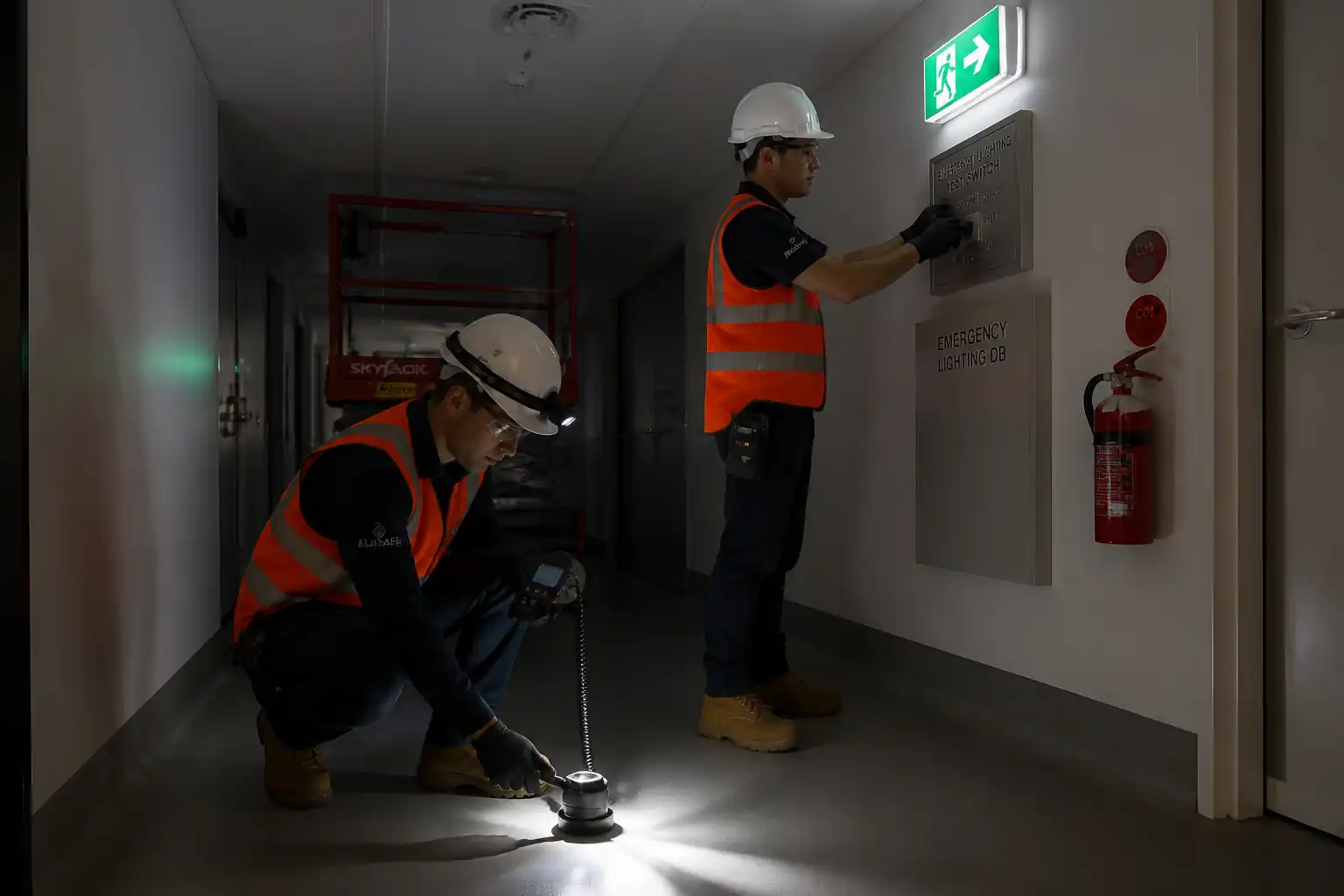
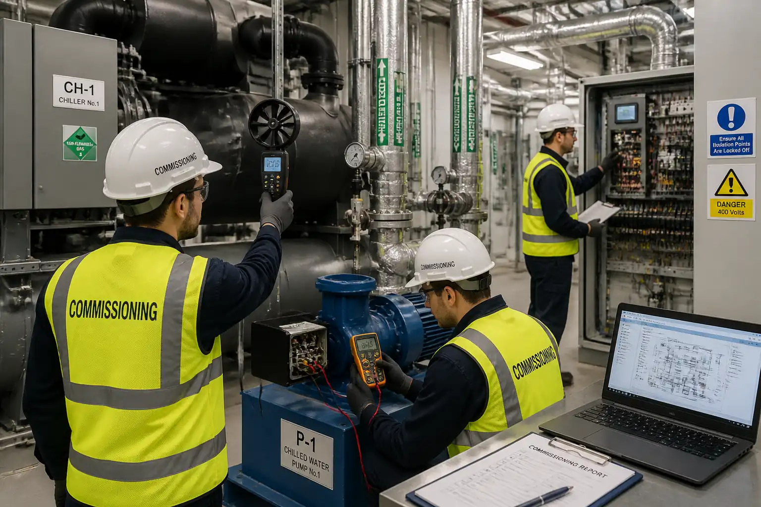
| 13 | Functional Tests | Operate protective devices, lighting controls, emergency lighting changeover, contactors, interfaces with FA/BMS where applicable. | T&C Engineer | Client/Consultant witness (as scheduled) |
| 14 | Labelling & Schedules | Affix permanent labels to DBs and devices; update DB schedules with circuit IDs, protective devices, Zs, IR, RCD details. | Electrician / Doc Control | QA/QC verification |
| 15 | Defects & Re-testing | Record non-conformances; rectify terminations, substitutions, or settings; re-test affected circuits. | T&C Engineer / Electrician | QA/QC closeout |
| 16 | Final Documentation and Certification | Compile test sheets, calibration certificates, as-built markups, and issue EIC/CoC for Client/Consultant approval. | T&C Engineer / QA/QC | Final review |
Health, Safety, and Environment – Safety Controls
Principal Hazards and Controls
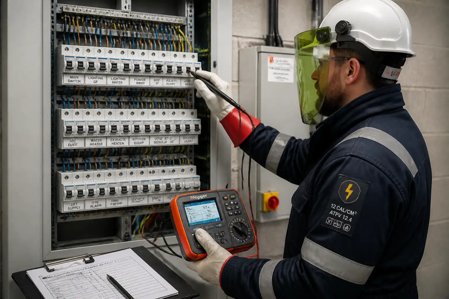
- Hazard: Contact with live conductors during live tests
- Likely consequence: Electric shock, burns, fatality
- Engineering/procedural control: Plan live work only where unavoidable; use non-contact/indirect tests where practicable; barriers and insulated matting; keep one-hand rule; GS38 fused leads; maintain approach boundaries
- Required PPE: Arc-rated clothing (as assessed), insulated gloves, eye/face protection, safety footwear
- Collective measure: Permit-to-Work, live testing procedure, exclusion zone and attendants
-
Inspection/permit/supervision: PTW approval by AP; HSE oversight; tester condition check before/after
-
Hazard: Arc flash at DBs/incomers
- Likely consequence: Burns, blast injuries, hearing loss
- Engineering/procedural control: Fault level assessment; de-energize where possible; use properly rated CAT III/IV instruments; close panel doors if design allows; stand to side when switching
- Required PPE: Arc-rated suit/gloves, face shield, hearing protection
- Collective measure: Arc-flash boundary, insulated barriers
-
Inspection/permit/supervision: Live work risk assessment and authorization [Verify per project HSE plan and local regulations]
-
Hazard: Incorrect isolation/LOTO
- Likely consequence: Inadvertent energization
- Engineering/procedural control: Positive isolation at source; unique LOTO; prove dead with approved two-pole tester; apply lock and tag with contact details
- Required PPE: Standard electrical PPE
- Collective measure: LOTO register managed by AP
-
Inspection/permit/supervision: PTW; audit of LOTO before work
-
Hazard: Working at height to access high-mounted equipment
- Likely consequence: Falls, injury
- Engineering/procedural control: Use podium steps or mobile scaffold with guardrails; avoid ladders unless short light-duty task; inspect access equipment
- Required PPE: Hard hat, non-slip footwear, fall protection where required
- Collective measure: Exclusion zone beneath; spotter
-
Inspection/permit/supervision: Pre-use inspection; work-at-height permit if applicable
-
Hazard: Tools/parts causing short circuits inside DBs
- Likely consequence: Flash, equipment damage, injury
- Engineering/procedural control: Use insulated tools; keep hardware organized; fit temporary insulating shrouds; remove metallic jewelry
- Required PPE: Electrical gloves, eye protection
- Collective measure: Tool control checklist
-
Inspection/permit/supervision: Supervisor checks before energization
-
Hazard: Nuisance tripping affecting occupants/critical systems
- Likely consequence: Loss of service, data loss
- Engineering/procedural control: Coordinate outage windows; bypass/disable sensitive loads per OEM before RCD/IR tests; notify stakeholders
- Required PPE: N/A (administrative)
- Collective measure: Communication plan and signage
-
Inspection/permit/supervision: Approval from facility manager; method briefing
-
Hazard: Manual handling of DB covers and equipment
- Likely consequence: Strains, crush injuries
- Engineering/procedural control: Team lift for heavy covers; use appropriate fixings and storage of covers
- Required PPE: Gloves, safety boots
- Collective measure: Mechanical aids where feasible
-
Inspection/permit/supervision: Supervisor to brief team
-
Hazard: Poor illumination in plant rooms
- Likely consequence: Trips, misreading instruments
- Engineering/procedural control: Provide task lighting; confirm emergency lighting availability
- Required PPE: Head torch as needed
- Collective measure: Temporary lighting
-
Inspection/permit/supervision: Pre-task check list
-
Hazard: Noise in active buildings
- Likely consequence: Miscommunication
- Engineering/procedural control: Use radios/hand signals; pre-brief; signage
- Required PPE: Hearing protection if required
- Collective measure: Controlled access
- Inspection/permit/supervision: Supervisor coordination
Environmental Controls
Controls
- Battery and Electronic Waste
- Risk: Improper disposal of tester batteries and failed electronic components
-
Control: Collect and dispose via approved e-waste channels; no landfill; maintain waste transfer notes
-
Labelling and Packaging Waste
- Risk: General waste accumulation
-
Control: Segregate recyclable backing paper/cardboard; use refillable label cassettes where possible
-
Nuisance from Testing Activities
- Risk: Disturbance to occupants during switching/testing
-
Control: Schedule out-of-hours; provide prior notice; use signage to reduce complaints
-
Energy and Carbon
- Risk: Unnecessary energization/time under load
-
Control: Minimize test duration; de-energize promptly after tests; use energy-efficient task lighting
-
Chemical Exposure
- Risk: Aerosols/cleaners for DBs
-
Control: Use low-VOC cleaners; avoid solvent discharge; follow SDS
-
Spills/Housekeeping
- Risk: Trip hazards from leads/mats
-
Control: Cable management; tidy work area; remove all materials after testing
-
Compliance
- Records: Maintain waste logs and SDS; comply with local environmental regulations [Verify per local law]
Quality Assurance and Quality Control
QA/QC Strategy
- Testing Coverage: 100% of final circuits shall be tested for CPC continuity, IR, polarity; Zs and RCD tests performed on representative points per circuit and at extremities as required by the standard [Verify per project specifications].
- Calibration: All instruments hold valid ISO/IEC 17025 calibration certificates; daily pre-use checks logged.
- Witnessing: Hold/Witness points as per ITP for isolation, live testing, Zs/RCD, and final certification. Minimum 48 h notice to Client/Consultant.
- Test Records: Use approved forms capturing circuit ID, protective device, conductor sizes/lengths (if known), ambient temperature, test settings, and measured values.
- Acceptance Criteria: Per IEC 60364-6/BS 7671 and device standards. Where tabulated limits apply (Zs, disconnection times), reference the device type, rating, and system earthing; apply correction factor Cmin where required [Verify per project].
- Labelling and Traceability: Each DB and circuit to have durable ID matching schedules and test sheets; cross-reference page/record numbers.
- Nonconformance Control: Record NCRs for any failures; identify root cause (e.g., loose termination, damaged cable, wrong device rating); correct and re-test; document closure with signatures.
- Document Control: All results compiled into a test dossier; revisions tracked; final EIC/CoC signed by authorized signatory with license number [Verify per jurisdiction].
- Data Integrity: No overwriting; if corrections needed, strike-through single line with initials/date; maintain electronic backups.
Attachments
Attachments / Appendices
- Sample test sheets: Continuity, IR, Polarity, Zs, PFC, RCD
- Example DB schedule format with fields for device type/rating, Zs, IΔn, circuit description
- Instrument list with calibration certificates (ISO/IEC 17025)
- PTW and LOTO forms
- Risk Assessment / Method Statement (RAMS) for live testing
- NCR and punch list templates
- Manufacturer torque data sheets (typical ranges) [Verify per OEM]
- Extracts from IEC 60364-6/BS 7671 guidance for verification (for reference only)
- Handover dossier index and EIC/CoC template [Verify per jurisdiction]
This content is a read-only public reference. Download or customize to get an editable version.
ITP preview
The first inspection activities from the linked ITP for Method Statement – Final Electrical Circuit Testing for Building Handover:
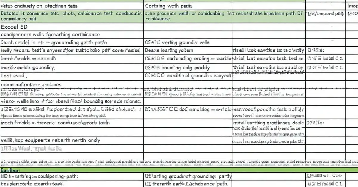
| Activity | Inspection / Test | Acceptance Criteria | Responsibility | Record |
|---|---|---|---|---|
| ITP and Method Approval | Document approval | Approved ITP and method statement prior to start. | Project Manager / QA-QC / Client | Approved ITP/MS |
| Calibration Verification | Calibration validity | ISO/IEC 17025 certificates in date for all testers. | QA/QC Engineer | Calibration log, copies of certs |
| Isolation and LOTO | Prove dead | PTW active; correct isolation; prove-dead confirmed. | AP / HSE / QA-QC | PTW, LOTO register |
Showing 3 of 16 inspection activities. View full ITP →
Related Inspection and Test Plan
An Inspection and Test Plan (ITP) is available for Method Statement – Final Electrical Circuit Testing for Building Handover. The ITP defines the inspection activities, acceptance criteria, hold and witness points, responsible parties, and records required to verify the work described in this method statement.
View the Method Statement – Final Electrical Circuit Testing for Building Handover ITP →Frequently asked questions
Continue with related Quollnet resources connected to this method statement.