
Inspection and Test Plan for Method Statement – Final Electrical Circuit Testing for Building Handover
AI-assisted inspection and test plan connected to a method statement, with PDF and Excel export.
More than a static template
Unlike a downloadable Word or PDF template, this ITP is an AI-assisted editable starting point directly connected to its method statement. Every inspection activity, hold point, and acceptance criterion is structured and ready to adapt to your project.
- AI-assisted customization — Tailor inspection activities and acceptance criteria to your specific project scope.
- Linked method statement — This ITP is connected to the corresponding method statement describing the work sequence.
- Multiple export formats — Download as a formatted PDF or editable Excel spreadsheet.
- Editable starting point, not a final document — Review and verify all content against your project specifications and standards before use.
What you can customize
When you save this ITP to your account, every inspection row becomes editable. You can add, remove, or modify:
- Inspection activity — Description of what is being inspected.
- Inspection type — Hold point (H), Witness point (W), Review (R), or Monitor (M).
- Responsibility — Contractor, subcontractor, engineer, or client.
- Frequency — How often the inspection occurs.
- Acceptance criteria — Referenced standard or specification requirement.
- Records — Forms, test reports, or checklists required as evidence.
Why this ITP is used
To control and verify that all final circuits meet safety and performance requirements before handover.
Who uses this inspection and test plan
T&C engineers, electricians, QA/QC, HSE, and Client/Consultant representatives.
When this ITP is prepared and submitted
After installation completion and before energization and handover.
Who receives or approves this ITP
Client/Consultant for approval and witnessing.
Inspection scope
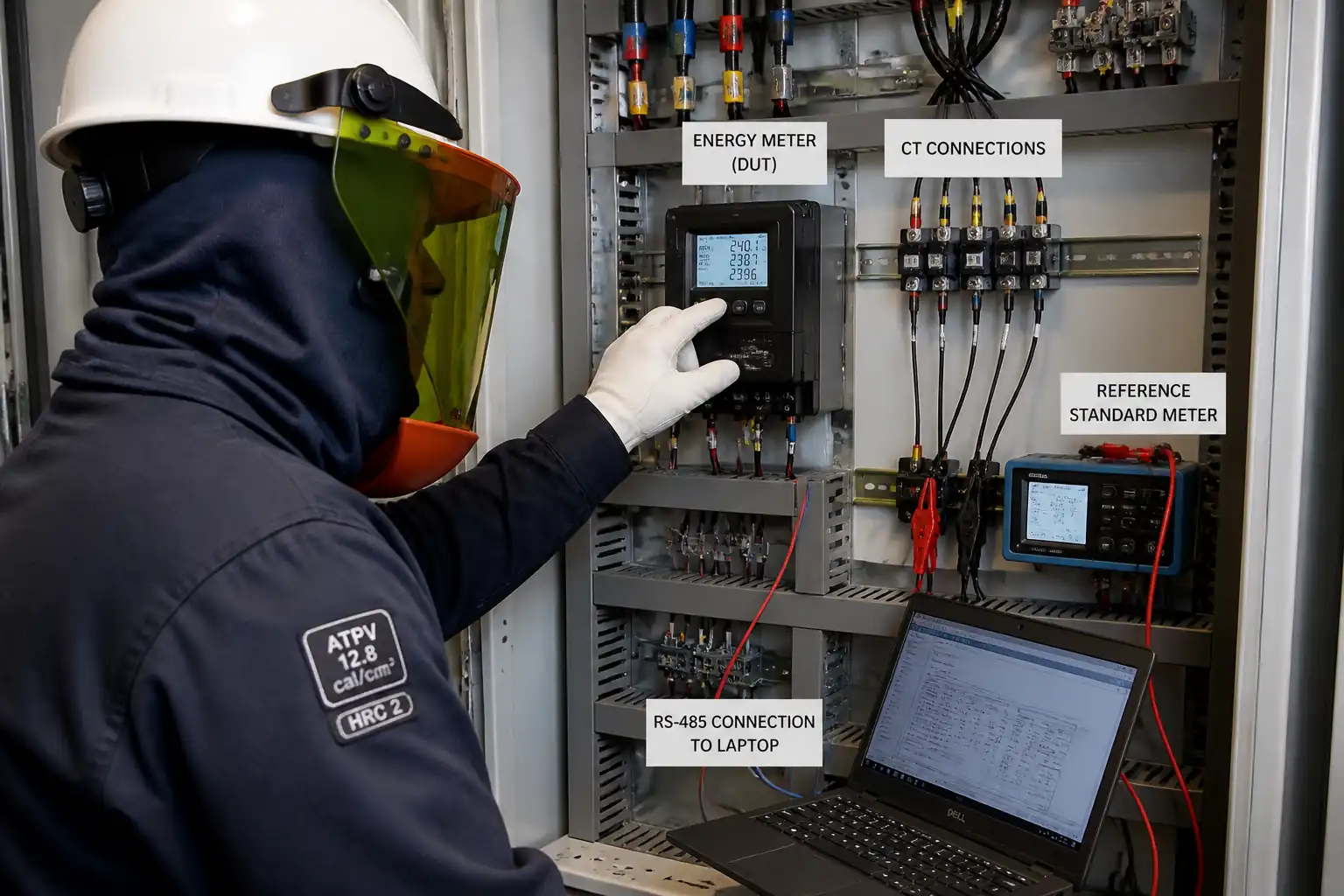
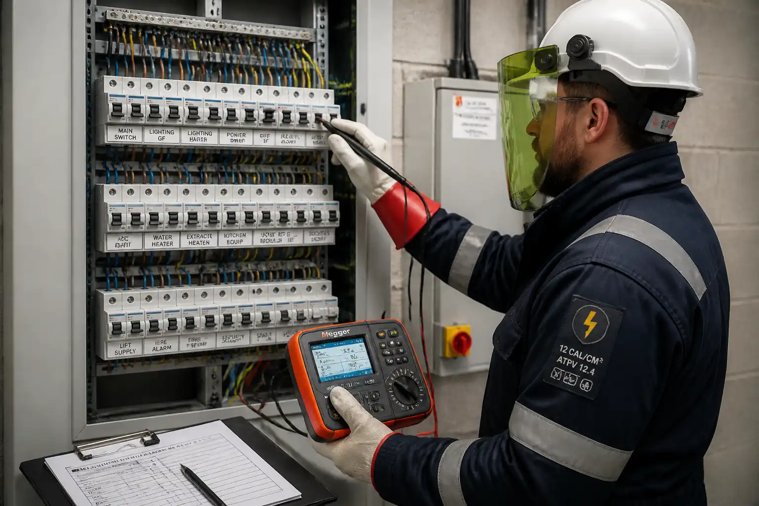
Covers document review, calibration, isolation/LOTO, dead tests, live tests (Zs, PFC, RCD), functional checks, labelling, and final certification.
Typical hold, witness, and review points
Hold: Isolation/LOTO, pre-energization, final certification. Witness: CPC continuity, ring continuity, IR, Zs, RCD, functional tests.
Typical inspection records
Approved ITP, test sheets, calibration logs, PTW/LOTO, NCRs, updated DB schedules, EIC/CoC, as-builts.
Important approval note
This ITP is an AI-assisted editable starting point, not a pre-approved document. Before use on any project, all inspection activities, hold points, and acceptance criteria must be reviewed and approved by the relevant parties (superintendent, principal contractor, or client representative) in accordance with your contract and project quality plan.
Always verify acceptance criteria against your applicable drawings, specifications, and regulatory requirements. Hold points must be confirmed with the relevant authority before work proceeds past that point.
Inspection and test plan
| Activity | Inspection / Test | Acceptance Criteria | Responsibility | Record |
|---|---|---|---|---|
| ITP and Method Approval | Document approval | Approved ITP and method statement prior to start. | Project Manager / QA-QC / Client | Approved ITP/MS |
| Calibration Verification | Calibration validity | ISO/IEC 17025 certificates in date for all testers. | QA/QC Engineer | Calibration log, copies of certs |
| Isolation and LOTO | Prove dead | PTW active; correct isolation; prove-dead confirmed. | AP / HSE / QA-QC | PTW, LOTO register |
| Visual and Mechanical Checks | Torque to OEM | All terminations torqued; components undamaged; IP maintained. | Electrician / QA-QC | Visual/torque checklist |
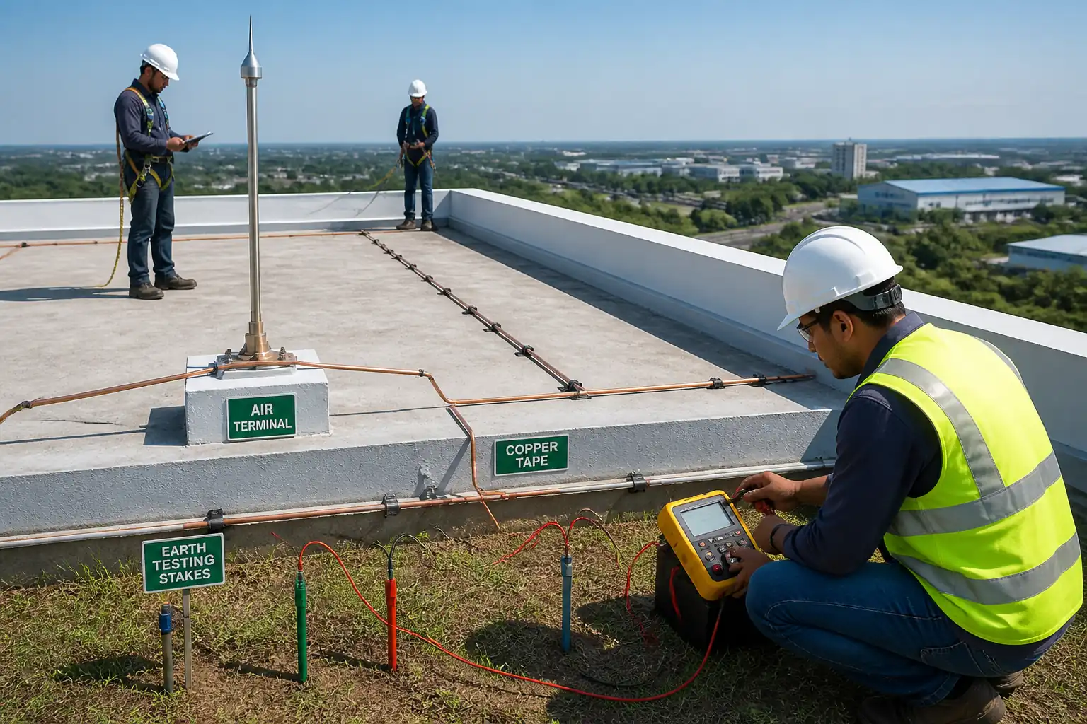
| Continuity of CPC (R1+R2) | Continuity ≥200 mA | No open circuits; R1+R2 supports Zs compliance. | Electrician / QA-QC | Continuity results |
| Ring Final Circuit Continuity | Cross-connection method | Balanced readings within tolerance; correct polarity. | Electrician / Consultant | Ring test sheet |
| Insulation Resistance (IR) | IR 500 V DC (or 250 V DC) | ≥1.0 MΩ (LV), ≥0.5 MΩ (SELV/PELV or with electronics) [Verify] | Electrician / QA-QC | IR results |
| Polarity | Polarity/phase sequence | Switches in line; correct socket and phase sequence. | Electrician / QA-QC | Polarity sheet |
| Energization Checkpoint | Pre-energization checklist | All dead tests passed; controls in place for live tests. | AP / HSE / Client | Checklist signed |
| Earth Fault Loop Impedance (Zs) | Loop (non-trip if RCD) | Zs ≤ maximum permissible for device/system per code tables [Verify] | Electrician / Consultant | Zs results |
| Prospective Fault/Short Circuit Current (PFC/PSC) | PFC/PSC | Protective device Icn/Icu ≥ measured PFC/PSC. | Electrician / QA-QC | PFC records |
| RCD Performance | Time at 1×/5× IΔn; ramp | Trip times within BS EN 61008/61009; ramp within expected band [Verify] | Electrician / Consultant | RCD results |
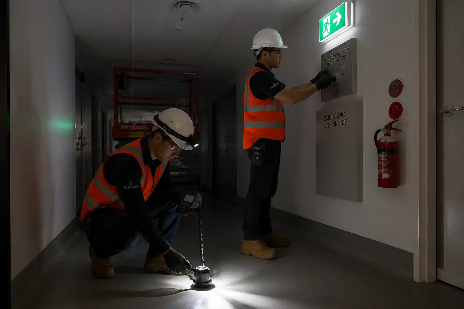
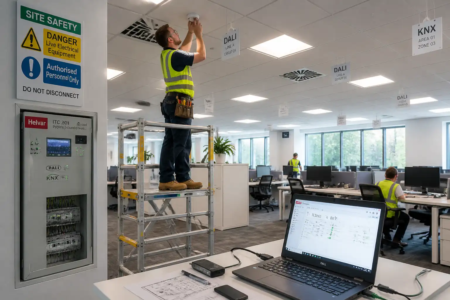
| Functional Tests | Functional sequences | Intended operation and interlocks confirmed. | T&C Engineer / Client | Functional test forms |
| Labelling and Schedules | Label verification | Correct, durable labels; schedules updated and accurate. | Electrician / QA-QC | Label audit sheet; final schedules |
| Defect Rectification and Re-test | Repeat failed tests | All NCRs closed; results conform. | T&C Engineer / QA-QC | NCR log; re-test forms |
| Final Certification and Handover | Dossier completeness | Signed EIC/CoC, as-builts, calibration, ITP sign-offs submitted and approved. | Authorized Signatory / Client | Handover dossier |
This table is a read-only public reference. Download the PDF or Excel version, or customize this ITP to edit it for your project.
Frequently asked questions
Related method statement
This Inspection and Test Plan is associated with the Method Statement – Final Electrical Circuit Testing for Building Handover method statement, which describes the step-by-step construction sequence, resources, materials, equipment, safety controls, and environmental controls for this activity.
View the Method Statement – Final Electrical Circuit Testing for Building Handover method statement →Continue with related inspection, method statement, article, and checklist resources.