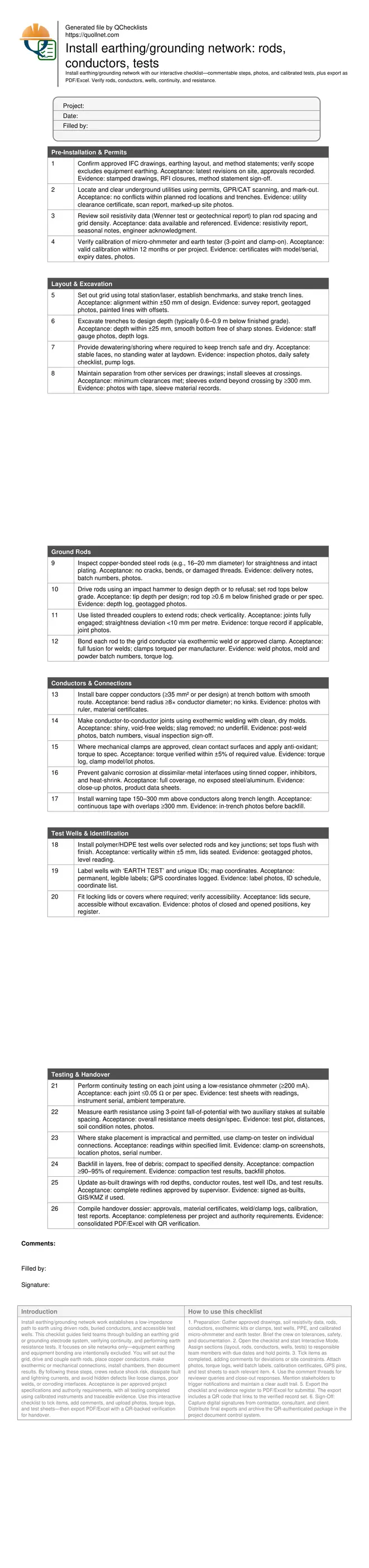
Install earthing/grounding network: rods, conductors, tests
Definition: Install earthing/grounding network checklist for contractors and inspectors, covering rods, buried conductors, test wells, continuity and resistance testing, excluding equipment earthing scope.
- Plan grid layout from approved drawings and soil resistivity data
- Install rods and conductors with verified joints and corrosion control
- Confirm continuity and earth resistance with calibrated instruments and records
- Interactive, commentable, export, QR code verification for auditable sign-off
Install earthing/grounding network work establishes a low-impedance path to earth using driven rods, buried conductors, and accessible test wells. This checklist guides field teams through building an earthing grid or grounding electrode system, verifying continuity, and performing earth resistance tests. It focuses on site networks only—equipment earthing and equipment bonding are intentionally excluded. You will set out the grid, drive and couple earth rods, place copper conductors, make exothermic or mechanical connections, install chambers, then document results. By following these steps, crews reduce shock risk, dissipate fault and lightning currents, and avoid hidden defects like loose clamps, poor welds, or corroding interfaces. Acceptance is per approved project specifications and authority requirements, with all testing completed using calibrated instruments and traceable evidence. Use this interactive checklist to tick items, add comments, and upload photos, torque logs, and test sheets—then export PDF/Excel with a QR-backed verification for handover.
- Comprehensive field workflow for setting out, installing, and verifying the earthing/grounding network. It covers rods, buried conductors, jointing, corrosion mitigation, accessible test wells, continuity checks, and earth resistance testing, with acceptance per approved project specifications and authority requirements.
- Interactive online checklist with tick, comment, and export features secured by QR code. Field teams attach photos, instrument certificates, torque logs, and GPS tags, enabling transparent reviews and auditable sign-offs without paperwork delays or version confusion across subcontractors and consultants.
- Clear test methodology for continuity and earth resistance, including 3-point fall-of-potential and clamp-on alternatives where permitted. The checklist explains evidence capture, common failure causes, and corrective options such as adding rods, improving couplings, or adjusting grid geometry before concealment.
- Practical tolerances, bend radii, separation, and backfilling cues help avoid rework and damage. Crews finish with accurate as-builts, labelled chambers, and a complete dossier—ensuring safe operation, long-term reliability, and streamlined compliance on substations, plants, or building sites.
Pre-Installation & Permits
Layout & Excavation
Ground Rods
Conductors & Connections
Test Wells & Identification
Testing & Handover
Plan the Grid with Soil Data and Clear Scope Boundaries
A reliable earthing grid begins with sound planning. Use approved drawings and soil resistivity data to determine rod spacing, grid density, and conductor sizing. Seasonal moisture swings can shift results, so document ground conditions when testing. Confirm this scope excludes equipment earthing and bonding; the focus is on rods, buried conductors, and test wells forming the grounding electrode system. Coordinate utility clearances early to avoid conflicts at rod locations and crossings. Establish survey control, then mark trench routes and well positions with clear offsets. Prepare method statements that specify exothermic welding or mechanical clamps, corrosion mitigation at dissimilar metals, bend radii, and acceptance tests. Calibrate instruments before mobilization and ensure certificates are current. Hold a pre-start briefing so crews understand tolerances, testing procedures, and documentation needs for traceability throughout installation and commissioning.
- Use soil resistivity data to size and space rods and conductors
- Exclude equipment earthing; focus on site earthing network only
- Secure utility clearances and mark routes with survey control
- Define jointing method, corrosion control, and test acceptance
- Verify test instrument calibration and documentation readiness
Install Rods and Conductors with Robust, Inspectable Joints
Drive copper-bonded steel rods to the designed depth or refusal and couple extensions with listed fittings, keeping straightness within practical tolerances. Lay bare copper conductors on smooth trench bottoms, avoiding sharp bends; maintain a bend radius of at least eight times the conductor diameter. Use exothermic welding where specified for permanent, low-resistance joints; clean and dry molds, then verify solid fusion and remove slag. For approved mechanical clamps, clean contact surfaces, apply anti-oxidant, and torque to the manufacturer’s value. Prevent galvanic corrosion at bimetallic interfaces with tinned copper, inhibitors, and heat-shrink sleeves. Install warning tape above conductors for future locates. Construct test wells plumb and flush for lifetime access to rods and junctions, and assign traceable IDs and GPS coordinates. Photograph stages before concealment to preserve evidence.
- Maintain bend radius ≥8× conductor diameter; avoid kinks
- Verify weld quality visually; record batch numbers
- Torque mechanical clamps within ±5% of spec
- Protect dissimilar-metal joints with inhibitors and sleeves
- Install labelled, plumb test wells with GPS positions
Test Methodically and Document for Long-Term Assurance
Validate connections with a low-resistance ohmmeter that supplies sufficient test current, recording each joint’s reading and ambient conditions. Measure overall earth resistance using the 3-point fall-of-potential method; space auxiliary stakes appropriately and capture the curve to confirm a stable result. Where stake deployment is impractical and allowed, use clamp-on measurements on individual connections to screen performance. If readings exceed targets, add rods, improve couplings, lengthen conductors, or adjust grid geometry as directed. Backfill in controlled layers and compact to specified density, then restore finishes. Compile a complete dossier: calibrated instrument certificates, material records, weld/clamp logs, test sheets, photos, and signed as-builts. This record supports compliance, future maintenance, and troubleshooting over the asset’s life.
- Record continuity results per joint with instrument serials
- Capture fall-of-potential plots and electrode spacings
- Use clamp-on tests where staking is constrained
- Remediate high resistance by adding electrodes or improving joints
- Deliver a consolidated, signed handover package
Prepare, Use, and Sign Off the Interactive Checklist
- Preparation: Gather approved drawings, soil resistivity data, rods, conductors, exothermic kits or clamps, test wells, PPE, and calibrated micro-ohmmeter and earth tester. Brief the crew on tolerances, safety, and documentation.
- Open the checklist and start Interactive Mode. Assign sections (layout, rods, conductors, wells, tests) to responsible team members with due dates and hold points.
- Tick items as completed, adding comments for deviations or site constraints. Attach photos, torque logs, weld batch labels, calibration certificates, GPS pins, and test sheets to each relevant item.
- Use the comment threads for reviewer queries and close-out responses. Mention stakeholders to trigger notifications and maintain a clear audit trail.
- Export the checklist and evidence register to PDF/Excel for submittal. The export includes a QR code that links to the verified record set.
- Sign-Off: Capture digital signatures from contractor, consultant, and client. Distribute final exports and archive the QR-authenticated package in the project document control system.
Call to Action
- Start Checklist Tick off tasks, leave comments on items or the whole form, and export your completed report to PDF or Excel—with a built-in QR code for authenticity.
- Download Excel - Earthing/Grounding Network Installation
- Download PDF - Earthing/Grounding Network Installation
- View Image - Earthing/Grounding Network Installation
Cite & Embed
“Earthing/Grounding Network Installation by Quollnet”
with a link to
this source page.
FAQ
Question: What is an acceptable earth resistance value for a site earthing network?
Question: When should I use exothermic welding versus mechanical clamps for connections?
Question: How do I test earth resistance when I cannot place remote stakes?
Question: What steps reduce corrosion in the earthing network over time?
Question: Why do resistance readings vary with seasons, and how should I report them?
Related Articles
Broader reading and guidance connected to this checklist topic.


Concrete Cube Test Register Excel Format – Pdf & Excel Sample

Related Checklists
Keep the workflow moving with nearby templates chosen from similar checklist content.