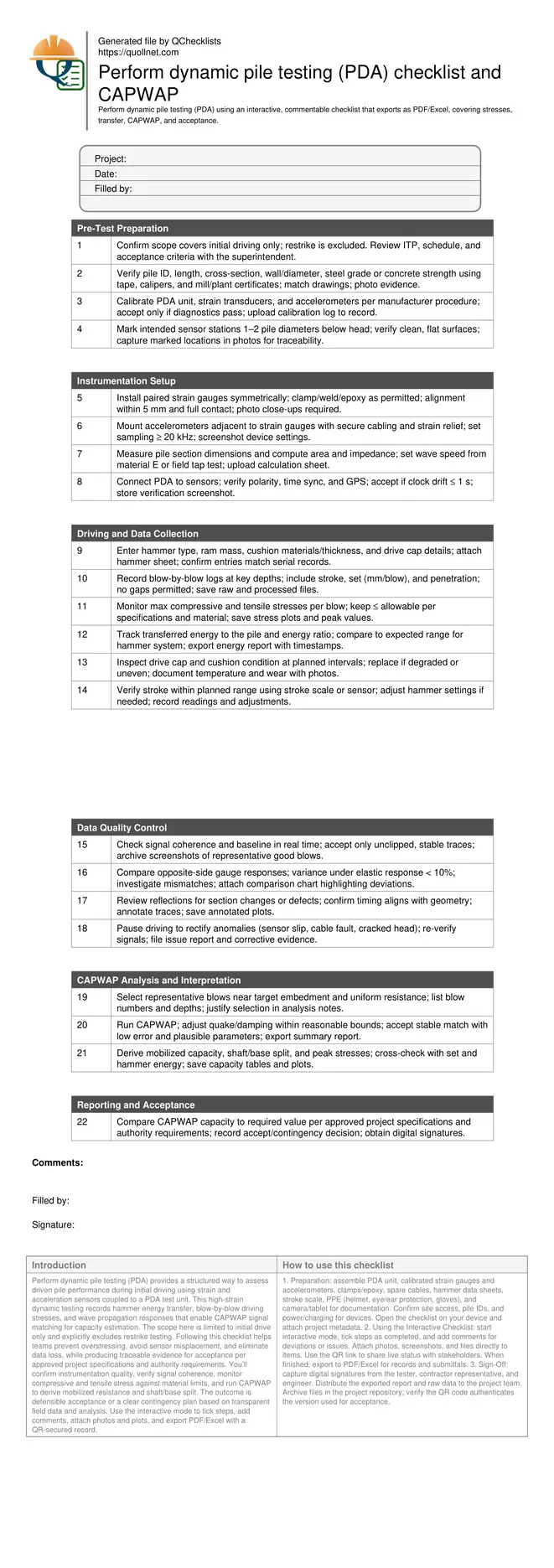
Perform dynamic pile testing (PDA) checklist and CAPWAP
Definition: Perform dynamic pile testing (PDA) guides field engineers in capturing driving stresses, energy transfer, and CAPWAP capacity estimates for acceptance of driven piles during initial driving operations.
- Capture reliable strain, acceleration, and energy data during initial driving.
- Control driving stresses against material limits with real-time thresholds.
- Run CAPWAP signal matching to estimate capacity and damping parameters.
- Interactive, commentable checklist; export to PDF/Excel with QR code.
Perform dynamic pile testing (PDA) provides a structured way to assess driven pile performance during initial driving using strain and acceleration sensors coupled to a PDA test unit. This high-strain dynamic testing records hammer energy transfer, blow-by-blow driving stresses, and wave propagation responses that enable CAPWAP signal matching for capacity estimation. The scope here is limited to initial drive only and explicitly excludes restrike testing. Following this checklist helps teams prevent overstressing, avoid sensor misplacement, and eliminate data loss, while producing traceable evidence for acceptance per approved project specifications and authority requirements. You’ll confirm instrumentation quality, verify signal coherence, monitor compressive and tensile stress against material limits, and run CAPWAP to derive mobilized resistance and shaft/base split. The outcome is defensible acceptance or a clear contingency plan based on transparent field data and analysis. Use the interactive mode to tick steps, add comments, attach photos and plots, and export PDF/Excel with a QR-secured record.
- This checklist standardizes PDA testing during initial driving, guiding crews through sensor installation, calibration, and data capture at adequate sampling rates. It reduces rework by catching wiring faults, misaligned gauges, and hammer setup issues before data collection, ensuring reliable stress and energy transfer measurements for defensible analysis.
- Interactive online checklist with tick, comment, and export features secured by QR code. Use it to standardize documentation across crews and subcontractors, improving traceability, accountability, and handover efficiency on complex foundation projects with multiple hammer types and pile sections.
- The workflow focuses on stress control and energy transfer, enabling timely CAPWAP signal matching to estimate mobilized capacity and damping parameters. Field teams receive clear acceptance cues, including plausible parameter ranges, stable matching, and alignment with observed set and driving resistance at target embedment.
Pre-Test Preparation
Instrumentation Setup
Driving and Data Collection
Data Quality Control
CAPWAP Analysis and Interpretation
Reporting and Acceptance
Instrumentation, placement, and reliable data acquisition
Quality PDA results start with correct sensor selection, placement, and calibration. Install paired strain gauges and accelerometers 1–2 pile diameters below the head on clean, flat surfaces. Follow manufacturer procedures for clamping, welding, or epoxy bonding, and secure cables with strain relief to prevent motion-induced noise. Set sampling at or above 20 kHz to capture high-frequency stress waves. Before driving, confirm impedance inputs (area and wave speed) from measured geometry and realistic material properties or a tap test. Verify GPS, time stamps, and polarity so that field and analysis files align. Run a brief pre-drive tap or low-energy blow to confirm signal coherence and that traces are free of clipping, drift, or cross-talk. These steps reduce false stress peaks, miscomputed energy, and unusable CAPWAP inputs. Document all placements, settings, and calibrations with photos, screenshots, and a short checklist note for each pile, enabling fast troubleshooting and defensible acceptance decisions later.
- Place sensors 1–2 diameters below the pile head.
- Use ≥ 20 kHz sampling to capture stress waves.
- Secure cables; provide strain relief and protect from abrasion.
- Verify polarity, time sync, GPS, and baseline stability.
- Record photos and screenshots for traceability.
Managing driving stresses and hammer energy transfer
During initial driving, monitor compressive and tensile stresses continuously and compare against allowable limits for the pile material and condition. Capture blow-by-blow data including stroke, set, and penetration. Verify that the hammer system delivers consistent, efficient energy transfer to the pile, and keep a watch on drive cap and cushion condition, especially under long driving or high resistances. Assess transferred energy ratio relative to expectations for the hammer and cushion; low ratios often indicate cushion degradation or misalignment. Record and correct anomalies immediately to avoid overstressing or data loss. Proper control of stresses and energy promotes safer operations, prevents damage, and provides inputs that make CAPWAP matching faster and more reliable. Maintain a clean, timestamped log for every depth interval so that analysts can relate stress peaks and set to the observed blow history and hammer adjustments without ambiguity.
- Track compressive and tensile stress each blow.
- Log stroke, set, and penetration with timestamps.
- Inspect cushion condition and even seating frequently.
- Compare transferred energy against expected ranges.
- Pause and correct anomalies before proceeding.
CAPWAP signal matching and acceptance decisions
Select representative blows around target embedment where driving is uniform and signals are clean. In CAPWAP, adjust quake and damping only within physically reasonable bounds and seek a stable, low-error match that produces plausible shaft/base resistance and damping values. Cross-check capacity and stress outputs against measured set, hammer energy, and observed behavior. Accept results that demonstrate consistency across multiple candidate blows or a clear rationale for the governing blow. The final decision should compare the mobilized capacity with the required value per approved project specifications and authority requirements. If capacity is short or parameters are unstable, propose contingencies such as hammer setting adjustments, more driving, or additional testing (excluding restrike here). Deliver a concise report with raw files, plots, and a signed acceptance page for transparent closeout.
- Choose clean, representative blows for matching.
- Seek stable matches with low error values.
- Confirm parameter plausibility and consistency.
- Compare results to required capacity criteria.
- Issue clear accept or contingency recommendation.
How to use this interactive PDA testing checklist
- Preparation: assemble PDA unit, calibrated strain gauges and accelerometers, clamps/epoxy, spare cables, hammer data sheets, stroke scale, PPE (helmet, eye/ear protection, gloves), and camera/tablet for documentation. Confirm site access, pile IDs, and power/charging for devices. Open the checklist on your device and attach project metadata.
- Using the Interactive Checklist: start interactive mode, tick steps as completed, and add comments for deviations or issues. Attach photos, screenshots, and files directly to items. Use the QR link to share live status with stakeholders. When finished, export to PDF/Excel for records and submittals.
- Sign-Off: capture digital signatures from the tester, contractor representative, and engineer. Distribute the exported report and raw data to the project team. Archive files in the project repository; verify the QR code authenticates the version used for acceptance.
Call to Action
- Start Checklist Tick off tasks, leave comments on items or the whole form, and export your completed report to PDF or Excel—with a built-in QR code for authenticity.
- Download Excel - Dynamic Pile Testing (PDA) – Initial Drive
- Download PDF - Dynamic Pile Testing (PDA) – Initial Drive
- View Image - Dynamic Pile Testing (PDA) – Initial Drive
Cite & Embed
“Dynamic Pile Testing (PDA) – Initial Drive by Quollnet”
with a link to
this source page.
FAQ
Question: What does PDA measure during initial driving, and why exclude restrike here?
Question: How do I control compressive and tensile stresses to prevent pile damage?
Question: What makes a CAPWAP match acceptable for capacity estimation?
Question: Which data quality checks are essential before running CAPWAP?
Related Articles
Broader reading and guidance connected to this checklist topic.


How To Use Quollnet To Predict Construction Project Cashflow
Related Checklists
Keep the workflow moving with nearby templates chosen from similar checklist content.