Install CSL Tubes on Piles: Installation and Sealing Checklist
Definition: Install CSL tubes on piles for drilled shafts, guiding contractors and inspectors to verify fixation, continuity, sealing, and complete records—excluding CSL testing—per approved project specifications and authority requirements.
- Define tube size, spacing, and fixation to reinforcement cage.
- Verify continuity with mandrel passes and tight, pressure-proof sealing.
- Capture photos, readings, and signatures for a defensible tube record.
- Interactive, commentable workflow with export and QR code verification.
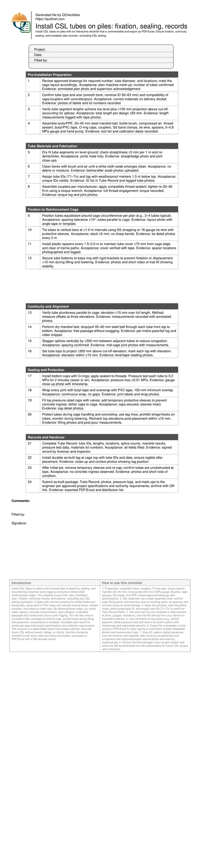
Install CSL tubes on piles is the focused task of attaching, sealing, and documenting crosshole sonic logging conduits on drilled shaft reinforcement cages. This checklist covers CSL tube installation only—fixation, continuity checks, and sealing—excluding any CSL testing operations. It aligns with common practice for drilled shafts and bored piles, using steel or PVC tubes with smooth internal bores, reliable couplers, and pressure-rated caps. By following these steps, you avoid water ingress, concrete contamination, tube collapse, or blocked passages that compromise future sonic logging. You will also ensure consistent tube coverage around the cage, protect tubes during lifting and placement, and produce a complete, traceable tube record for review per approved project specifications and authority requirements. The outcome is a dependable setup that enables efficient, accurate future CSL without rework, delays, or claims. Use this interactive checklist to tick items, add comments and photos, and export to PDF/Excel with a QR-secured record.
- This checklist standardizes CSL tube installation on drilled shaft piles, ensuring correct tube sizing, equal spacing, robust fixation to cages, and sealed ends. It prevents concrete ingress and blockage, keeping tubes aligned and continuous for future sonic logging without on-site rework.
- Technicians verify continuity using dry mandrel passes, align tops to accessible elevations, and pressure test sealing to a defined hold period. Ties, spacers, and brackets maintain cover and prevent movement during lifting and tremie placement, documented with photos and readings.
- The Tube Record consolidates tube IDs, locations, lengths, splice counts, pressure results, and sign-offs. Structured evidence reduces ambiguity, supports quality reviews, and accelerates approvals per approved project specifications and authority requirements, while clearly excluding CSL testing activities.
- Interactive online checklist with tick, comment, and export features secured by QR code. Users attach photos, note corrective actions, and generate a shareable PDF/Excel package for engineers and inspectors, creating a tamper-evident trail and consistent installation outcomes across crews and shifts.
Pre-Installation Preparation
Tube Materials and Fabrication
Fixation to Reinforcement Cage
Continuity and Alignment
Sealing and Protection
Records and Handover
Selecting and Preparing CSL Tubes for Drilled Shafts
Proper CSL tube selection underpins reliable future logging. Use smooth-bore tubes with a nominal internal diameter around 50–63 mm so probes pass freely. Match couplers and caps to the tube material and ensure sealants are compatible with concrete alkalis. Before attachment, clean every bore using a bottle brush and compressed air until a white cloth emerges clean; leftover rust scale or PVC shavings will trap debris during the pour. Check straightness with a straightedge; small kinks dramatically increase drag on the CSL probe. Dry-fit segments on the ground and torque couplers to manufacturer limits for a gas- and water-tight assembly. Assign durable tube IDs (T1–Tn) and log lot numbers and lengths. Field example: a contractor cut rework time by half after instituting a prefit-and-clean step, catching two dented segments and a mismatched coupler before cage lift.
- Use smooth bores; nominal ID 50–63 mm.
- Clean until a white swab is spotless.
- Torque couplers; verify full thread engagement.
- Label tubes clearly and record lot numbers.
- Reject dented or kinked segments immediately.
Fixation to the Reinforcement Cage Without Obstruction
Fixing tubes correctly keeps them continuous and accessible after the pour. Space tubes equally around the cage to the approved layout, typically three or four per pile depending on diameter. Tie at ≤1.0 m intervals with stainless strapping or protected tie wire; avoid sharp bends. Install plastic spacers every 1.5–2.0 m for consistent cover (≥75 mm from cage edge) and to keep tubes clear of tremie paths, rockers, and lifting points. Rigid brackets at the base prevent flotation when slurry or concrete displaces water. Confirm that splices are staggered between tubes to reduce congestion. Conduct a trial lift and rotate the cage to check that no tube snags rigging or formwork; adjust ties and spacers where needed. This proactive check often prevents crushed tees and lost continuity at the mat during lowering.
- Tie at ≤1.0 m intervals; avoid sharp bends.
- Maintain ≥75 mm cover using plastic spacers.
- Stagger splices by at least 300 mm.
- Perform a trial lift to verify stability.
- Keep clear of tremie and lifting paths.
Continuity, Sealing, and Documentation That Stands Up to Review
Continuity and sealing determine whether a probe can traverse the tubes after curing. Run a dry mandrel test with a 35–40 mm steel ball to confirm unobstructed passage and log the results per tube. Seal the bottom with O-ring caps and apply thread sealant to joints. Pressure test each tube to 0.2 MPa for two minutes; acceptable loss is ≤0.01 MPa, which reveals pinholes before the pour. Protect top caps with sleeves and ensure they project ≥300 mm above cut-off so future access is simple. After placement, re-check top elevations and remove sleeves only when safe. Compile a Tube Record with IDs, lengths, locations, splice counts, mandrel results, pressure readings, and photos. This package accelerates approvals per approved project specifications and authority requirements while clearly excluding CSL testing operations.
- Mandrel pass confirms continuity pre-pour.
- Pressure test: 0.2 MPa, 2 minutes, ≤0.01 MPa loss.
- Top projection ≥300 mm above cut-off.
- Protect caps with sleeves during concreting.
- Complete a signed Tube Record with photos.
How to Use This Interactive CSL Tube Installation Checklist
- Preparation: assemble tubes, couplers, O-ring caps, torque wrench, mandrel (35–40 mm), hand pump with 0–0.6 MPa gauge, brushes, tape, spacers, SS straps, and PPE; review approved drawings and specifications.
- Site readiness: set a clean assembly area, confirm cage lifting points, and brief the crew on handling tubes, tie spacing, and no-hook zones to avoid damage.
- Open the checklist, start interactive mode, select project/pile ID, and assign tube IDs (T1–Tn) to prefill the Tube Record fields.
- Tick each item as you complete it; attach photos of joints, gauges, elevations, and trial lifts directly from your device for traceable evidence.
- Use comments to flag issues (e.g., kinked segment, failed pressure hold) and record corrective actions with timestamps and responsible persons.
- Export the in-progress or final record to PDF/Excel for daily reports or submittals; include embedded photos and measurement logs.
- Sign-off: capture digital signatures from the foreman and inspector after verifying completeness and compliance with approved project specifications and authority requirements.
- Archive the final package in your project system and share the QR-authenticated link with stakeholders for future CSL access and verification.
Call to Action
- Start Checklist Tick off tasks, leave comments on items or the whole form, and export your completed report to PDF or Excel—with a built-in QR code for authenticity.
- Download Excel - CSL Tube Installation on Piles
- Download PDF - CSL Tube Installation on Piles
- View Image - CSL Tube Installation on Piles
Cite & Embed
“CSL Tube Installation on Piles by Quollnet”
with a link to
this source page.
FAQ
Question: How many CSL tubes should I install on a pile and where should they go?
Question: Can I use PVC instead of steel for CSL tubes?
Question: What should I do if the mandrel ball hangs up during the continuity check?
Question: How do I prevent concrete or slurry from entering the tubes during the pour?
Question: When do I grout the CSL tubes?
Related Articles
Broader reading and guidance connected to this checklist topic.


Master Construction Project Cashflow With Cashflowpot

Is It Important To Customize Your Qr Code And How To Do It?
Download Excel Format Snag List
Related Checklists
Keep the workflow moving with nearby templates chosen from similar checklist content.