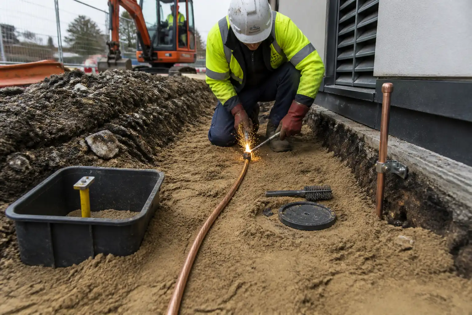

Method Statement: Installation of Perimeter Ground Ring with Bare Copper Conductor, Rebar Interconnection, Exothermic Welds, Earth Pits, and Testing – Method Statement
AI-assisted method statement with matching ITP, PDF download, and Excel export.
More than a static template
Unlike a downloadable Word or PDF template, this method statement is an AI-assisted editable starting point connected directly to a matching Inspection and Test Plan. Every section is structured, project-adaptable, and ready to export.
- AI-assisted drafting — Customize every section with AI for your specific project scope.
- Linked ITP — A matching inspection and test plan is generated alongside the method statement.
- Multiple export formats — Download as a formatted PDF or editable Excel spreadsheet.
- Editable starting point, not a final document — Review, verify, and adjust all content against your project requirements before use.
Static template vs. Quollnet workflow
| Feature | Static template | Quollnet |
|---|---|---|
| Project-specific content | Manual fill-in required | AI-assisted customization |
| Linked ITP | Separate document, no link | Matching ITP included |
| Export formats | Usually PDF only | PDF and Excel |
| Structured sections | Free-form layout | 13 standardized sections |
| Saved to your account | Local file only | Cloud-saved, reusable |
| Content accuracy | You verify everything | AI-assisted, you still verify |
| Cost | Often free but time-intensive | Free to customize and download |
What you can customize
When you save this method statement to your account, every section becomes editable. The following 13 sections are included:
- Scope — Defines the activity and its boundaries.
- References — Standards, specifications, and drawings.
- Responsibilities — Roles and accountabilities.
- Resources — Labour, plant, and equipment summary.
- Materials — Materials and compliance requirements.
- Equipment — Tools and equipment details.
- Prerequisites — Hold points and pre-conditions.
- Method sequence — Step-by-step construction sequence.
- Safety controls — HSE risk controls and PPE.
- Environmental controls — Environmental mitigation measures.
- QA/QC — Quality inspection and test requirements.
- ITP — Inspection and Test Plan table (has its own page).
- Attachments — Referenced drawings and documentation.
Why this method statement is used
This method statement is used to define and communicate the approved procedure for carrying out method statement: installation of perimeter ground ring with bare copper conductor, rebar interconnection, exothermic welds, earth pits, and testing on site. It ensures the work is planned in advance, the correct resources and controls are in place, and all personnel understand responsibilities, sequence, quality requirements, and safety controls before work begins. It aligns site execution with the documented scope and acceptance expectations.
Who uses this method statement
This method statement is used by contractors, site supervisors, project engineers, QA/QC engineers, HSE officers, consultants, and client representatives. It serves as a shared reference for planning, execution, supervision, inspection, and approval of the activity on site.
When it is prepared and submitted
The method statement is prepared before the work activity starts and submitted as part of the pre-construction documentation package for review and approval.
Who reviews or approves it
The method statement is usually submitted to the client representative, consultant, resident engineer, or project management consultant for review and approval before the work commences.
Important approval note
This method statement is an AI-assisted editable starting point, not a pre-approved document. Before use on any project, all content must be reviewed and approved by the relevant parties (superintendent, principal contractor, or client representative) in accordance with your contract and project quality plan.
For example: if your specification requires a departure from a referenced standard, that departure must be documented and approved separately — this method statement will not capture that automatically. Always verify against your applicable drawings, specifications, and regulatory requirements.
Method statement content
Scope
Workscope
- Install a buried bare copper ground ring encircling the building perimeter, including interconnections to structural column reinforcement, exothermic welded joints, earth electrodes (rods), and earth inspection pits with test links.
- Perform survey/set-out, utility clearance, trenching, conductor placement, welded/bonded connections, installation of earth pits and test links, backfilling and reinstatement, and comprehensive testing and documentation.
- Key hold points:
1) Conductor depth and alignment before backfilling (HP1).
2) Ring electrical continuity prior to backfilling and closure (HP2).
Limits/Interfaces
- From 1.0 m offset around building perimeter [Verify per drawings] to termination at the Main Earth Bar (MEB) or Main Earthing Terminal (MET) within the building electrical room.
- Interface with civil excavation/reinstatement, structural steel reinforcement, electrical earthing system, utilities, and landscape/roadway reinstatement.
Objectives
- Provide a low-impedance, corrosion-resistant, maintainable earthing system with target overall earth resistance typically ≤ 1.0 Ω for main building grids [Verify per project specifications], meeting shock protection and fault-clearing requirements.
References
| Document Type | Reference / Number | Revision | Notes |
|---|---|---|---|
| BS 7430 | |||
| IEC 60364-5-54 | |||
| IEEE Std 80 | |||
| IEEE Std 81 | |||
| IEC 62561-1/-2 | |||
| UL 467 | Use for listed clamps/links when specified | ||
| IEC 60228 / BS EN 13602 | |||
| BS 6031 / HSG47 | Or local excavation/utility regulations [Verify] | ||
| NFPA 70 Art. 250 | Use where jurisdiction requires NEC compliance | ||
| IEC 61557-5 |
Responsibilities
| Role | Responsibility | Name / Party |
|---|---|---|
| PM | Ensure method approval, programme integration, procurement | Contractor |
| CM | Sequence control; coordination of excavation and installation teams | Contractor |
| SE (Elec) | Set-out; compliance to specs; joint details; testing coordination | Contractor |
| QA/QC | Inspections, hold/witness points, records, NCR management | Contractor |
| HSEO | Task risk assessment, permits (excavation/hot works), monitoring | Contractor |
| Surveyor | Stakeout ring and pit locations; as-built coordinates | Contractor |
| Technician | Prepare, execute and inspect exothermic joints per manufacturer | Contractor/Approved Subcontractor |
| Engineer | Attend hold points for HP1 (depth) and HP2 (continuity); review tests | Engineer/Employer |
Resources
| Resource Type | Description | Quantity | Remarks |
|---|---|---|---|
| Manpower | Excavation crew (operator + 2 banksmen) | 1 team | |
| Manpower | Electrician + 2 helpers + exothermic technician | 1 team | |
| Manpower | 1 Surveyor + assistant | As required | |
| Manpower | QA/QC Engineer + inspector | As required |
Materials
| Material | Specification / Grade | Quantity | Remarks |
|---|---|---|---|
| Bare copper conductor | Min bend radius ≥ 8–12 × conductor diameter [Verify] | As per perimeter length + 10% | |
| Earth electrodes | Threaded couplers; drive points | At corners + every 20–30 m [Verify] | |
| Exothermic consumables | Weld types for straight, tee, and rebar bonds per schedule | As required for all joints | |
| Pit + test link | Stainless steel fixings; UV-stable lid | As per drawings (typically at each main entry point) | |
| Sand/soil | Non-angular sand to protect copper | As required | |
| Marker tape | Install 300 mm above conductor [Verify] | As required | |
| Protection materials | Per manufacturer’s data sheets | As required |
Equipment
| Equipment | Capacity / Type | Quantity | Inspection Required |
|---|---|---|---|
| Excavator | 1–2 | ||
| Shoring | As required | ||
| Compactor | As required | ||
| Weld kit | Sets per crew | ||
| Testers | 1 each | ||
| Rod driver | As required | ||
| Survey kit | As required | ||
| Locator/GPR | As required |
Prerequisites
Approvals and Documentation
- Approved shop drawings/route layouts, this Method Statement, and ITP.
- Permits: excavation permit, hot work permit for exothermic welding, utility NOCs/clearances [Verify per project HSE plan and local regulations].
- Calibrated test instruments with certificates.
- Manufacturer data sheets and procedure sheets for exothermic welding; SDS available on site.
Site Preparation
- Utility detection and marking using locator/GPR; trial holes by hand where required.
- Survey set-out of ring alignment, earth pit/test link locations, and offsets from structure.
- Traffic/pedestrian management plan and barriers installed.
Materials and Personnel
- Material Inspection Records (MIRs), certificates of conformity for copper conductor, earth rods, pits, connectors.
- Appointed competent exothermic welding technician(s) and trained crew; toolbox talk and task-specific risk assessment (RA) completed.
Environmental/Constraints
- Soil conditions checked (corrosivity, groundwater).
- Weather conditions suitable (no lightning risk during outdoor welding; rainfall controls/readiness).
Method Sequence
| Step | Activity | Description | Responsibility | Inspection / Hold Point |
|---|---|---|---|---|
| 1 | Set-out and utility clearance | Survey the ring path at ~1.0 m offset from building [Verify]. Mark utilities; hand-dig trial holes where crossings expected. | Site Engineer / Surveyor | Utility clearance records, set-out verified |
| 2 | Trench excavation (HP1) | Excavate continuous trench around perimeter to achieve minimum cover ≥ 600 mm, target depth 750 mm [Verify], width 300 mm. Provide shoring/battering. Maintain min 300 mm clearance from other services [Verify]. | Construction Manager | Depth/width check, stability, dewatering as needed |
| 3 | Bedding and conductor placement | Place 75–100 mm sand bedding. Unreel bare copper carefully on rollers; maintain min bend radius ≥ 8–12 × diameter [Verify]. Avoid kinks/mechanical damage. | Electrical Site Engineer | Visual; bend radius; support at corners |
| 4 | Exothermic welded joints—straight/tee/corners | Clean conductors with wire brush; dry molds; assemble per procedure. Execute welds; allow to cool; remove slag; visually examine. Tag each weld with unique ID and batch/charge no. | Exothermic Welding Technician | 100% visual inspection of each weld |
| 5 | Bonding to column reinforcement | Expose rebar tails or bonding points. Execute exothermic welds copper-to-rebar using dedicated molds. Ensure structural rebar continuity across joints via steel continuity or supplemental jumpers as detailed. | Electrical Site Engineer / Structural Rep. | Visual weld inspection; verify rebar continuity path |
| 6 | Earth rods installation | Drive copper-bonded rods at corners and every 20–30 m [Verify]. Couple sections to reach required depth; maintain verticality ±5°. Connect to ring via exothermic weld/clamp (UL 467/IEC 62561). | Electrical Crew | Rod depth and straightness; connection details |
| 7 | Earth pits and test links | Construct pits over selected electrodes and ring points as per drawings. Install test link (disconnect bar) with stainless hardware. Provide drainage layer in pit base. | Civil/Electrical | Pit alignment/level; link assembly |
| 8 | Ring continuity test (HP2) | With test links configured per test plan, measure continuity between consecutive access points using 4-wire micro-ohmmeter. Confirm no open circuits before backfill closure. | QA/QC with Site Engineer | Review test readings vs calculated values |
| 9 | Earth resistance testing | Perform 3- or 4-pole fall-of-potential test per IEEE 81 with all designated electrodes connected (unless testing individual elements). Place current probe ≥ 5× largest grid dimension or 30–50 m away [Verify]. | Qualified Tester | Instrument calibration; probe spacing adequacy |
| 10 | Backfilling and reinstatement | Place 100 mm sand surround; warning tape 300 mm above conductor; backfill and compact to 95% MDD (roads) / 90% MDD (landscape) [Verify]; reinstate surfaces. | Construction Manager | Compaction tests (as required); surface finish |
| 11 | As-built and handover | Survey as-built positions of ring, pits, rods; label test links; compile dossier of weld logs, certificates, test results, and redline drawings. | QA/QC / Surveyor | Document completeness review |
Health, Safety, and Environment (HSE) – Safety Controls
For each significant hazard, apply the following controls [Verify per project HSE plan and local regulations].
1) Hazard: Underground utility strike (electric, gas, telecom)
- Likely consequence: Electrocution, fire/explosion, major service disruption.
- Engineering/procedural control: Permit-to-dig; GPR/locator scan; utility maps; hand-dig within 1 m of marked services; insulated tools near live utilities.
- Required PPE: Dielectric gloves (as needed), safety boots, helmet with face shield, arc-rated PPE if near live equipment.
- Collective measure: Exclusion zones and barriers; spotter/banksman.
- Inspection/permit/supervision: Excavation permit; HSE Officer verification; utility representative as required.
2) Hazard: Trench collapse / falls into trench
- Likely consequence: Crush injury, burial, fall injury.
- Engineering/procedural control: Shoring/trench boxes or battered slopes per soil type; keep spoil ≥ 0.6 m from edge; safe access every 7.5–10 m; no plant near edges.
- Required PPE: Helmets, boots with ankle support, high-vis, gloves.
- Collective measure: Edge barriers, toe boards, stop logs for plant.
- Inspection/permit/supervision: Daily trench inspection by competent person; after rain or change in conditions.
3) Hazard: Exothermic welding (hot metal reaction)
- Likely consequence: Burns, fire, eye injury, fume inhalation.
- Engineering/procedural control: Hot work permit; follow manufacturer procedure; dry molds; keep flammables > 10 m away; pre-weld briefing; wind shield for sparks; dedicated fire watch 30 min post-weld.
- Required PPE: Face shield with IR/UV-rated visor, heat-resistant gloves, long-sleeve flame-resistant clothing, hearing protection, safety boots.
- Collective measure: Fire blanket beneath weld area; Class D fire extinguisher and sand bucket.
- Inspection/permit/supervision: Hot work permit; HSE oversight; technician competency verification.
4) Hazard: Plant–people interface (excavator/rod driving)
- Likely consequence: Struck-by, crush injuries.
- Engineering/procedural control: Segregated pedestrian routes; banksman for all movements; reversing alarms; lift plan for any lifting.
- Required PPE: High-vis, helmet, gloves, boots.
- Collective measure: Physical barriers and signage; exclusion zones.
- Inspection/permit/supervision: Daily plant checks; operator certification.
5) Hazard: Noise and vibration (rod driving/compaction)
- Likely consequence: Hearing damage, HAVS risk.
- Engineering/procedural control: Select low-vibration tools; duty rotation; maintain tools; schedule noisy tasks during permitted hours.
- Required PPE: Hearing protection (earmuffs/plugs), anti-vibration gloves.
- Collective measure: Acoustic screens if needed near sensitive receptors.
- Inspection/permit/supervision: Noise monitoring if required by permit.
6) Hazard: Manual handling of copper reels and pits
- Likely consequence: Strains, crush injuries.
- Engineering/procedural control: Use reel stands, team lifts, and mechanical aids; pre-task lift assessment.
- Required PPE: Gloves with good grip, boots.
- Collective measure: Keep storage close to workface; clear laydown areas.
- Inspection/permit/supervision: Supervisor to enforce manual handling plan.
7) Hazard: Electrical shock from adjacent energized systems
- Likely consequence: Shock, burns.
- Engineering/procedural control: De-energize where possible; lockout/tagout; maintain approach boundaries; use insulated mats/tools as required.
- Required PPE: Arc-rated PPE per risk assessment, dielectric gloves as applicable.
- Collective measure: Barriers and warning signs.
- Inspection/permit/supervision: LOTO permits; electrical supervisor oversight.
8) Hazard: Environmental exposure (heat, UV, weather)
- Likely consequence: Heat stress, dehydration, slips in wet conditions.
- Engineering/procedural control: Work/rest regime; hydration; shade; anti-slip controls; suspend welding during lightning.
- Required PPE: Weather-appropriate PPE, sunscreen.
- Collective measure: Welfare facilities and shelters.
- Inspection/permit/supervision: HSE to monitor heat index and weather alerts.
Environmental Controls
- Spoil management: Segregate topsoil and subsoil; stockpiles < 2 m high, > 5 m from drains; cover if windy/rainy.
- Erosion/sediment: Install silt fences and berms to prevent runoff; keep pits free of silt.
- Dust control: Water misting during dry weather; wheel wash for plant exiting site.
- Noise: Limit hours per permit; use maintained equipment; acoustic screens where necessary.
- Waste from exothermic welding: Collect slag and spent molds; dispose as non-hazardous mineral waste unless local rules differ [Verify].
- Copper protection: Avoid contamination with cementitious wash; do not leave offcuts in soil; scrap copper secured and recycled.
- Spills: Spill kits at workface; refuel in designated areas with trays; immediate cleanup and report.
- Vegetation/roots: Avoid damage to tree roots; adjust trench route with Engineer if needed.
- Water/storm events: Cover open trenches before storms; dewater to sediment control devices; no turbid discharge to drains.
- Reinstatement: Restore surfaces to original condition; reseed/topsoil in landscaped areas.
QA/QC
Quality Controls and Tolerances
- Trench depth: Target 750 mm; not less than 600 mm cover; tolerance +0/−50 mm [Verify].
- Trench width: ≥ 300 mm; tolerance +50/−0 mm.
- Offset from building: Typically 1.0 m [Verify].
- Bend radius: ≥ 8–12 × conductor diameter [Verify].
- Warning tape: 300 mm above conductor [Verify].
- Earth pit lids: Flush with finished level ±5 mm.
- Compaction: 95% MDD (trafficable); 90% MDD (landscaped) [Verify].
- Rebar bond continuity: ≤ 0.1 Ω from ring to connected rebar [Verify].
- Ring continuity: No open circuits; measured segment resistance broadly consistent with copper resistivity at 20°C (approx. 0.025 Ω per 100 m for 70 mm²) with allowance for joints/temperature ±20% [Verify conductor size/temperature correction).
- Earth resistance: Overall ≤ project requirement (typ. ≤ 1.0–2.0 Ω for buildings; ≤ 1.0 Ω commonly targeted) [Verify].
Testing
- Instruments: Earth testers conforming to IEC 61557-5; micro-ohmmeters with 4-wire Kelvin method; calibration within 12 months [Verify].
- Frequency: 100% inspection of all welds (visual); continuity tests at each accessible segment; ground resistance test upon completion and after any modification.
- Records: Weld log (ID, location, batch), MIRs, continuity and resistance test reports, calibration certificates, photos, as-built drawings.
Nonconformance and Corrective Action
- If continuity fails: locate defect via sectional testing; re-weld/replace joint; retest.
- If earth resistance exceeds target: add/lengthen electrodes, extend ring, apply soil enhancement (if approved), retest per IEEE 81.
- Document all NCRs and close-out with verification testing.
Hold/Witness Points
- HP1: Conductor depth and trench alignment before bedding/backfill.
- HP2: Ring continuity prior to backfill closure.
- WP: First-of-kind exothermic welds.
Attachments
- Approved shop drawings for ground ring route, pit locations, and details.
- Exothermic welding manufacturer procedure sheets and SDS.
- Typical details: copper-to-copper tee, copper-to-rebar connection, earth pit with test link.
- Checklists and forms: Excavation inspection, Weld log template, Continuity test sheet, Earth resistance test form, Backfill record.
- Calibration certificates for micro-ohmmeter and earth resistance tester.
- Risk Assessment and Method Statement (RAMS) including permits.
- As-built redline drawings and coordinates after completion.
This content is a read-only public reference. Download or customize to get an editable version.
ITP preview
The first inspection activities from the linked ITP for Method Statement: Installation of Perimeter Ground Ring with Bare Copper Conductor, Rebar Interconnection, Exothermic Welds, Earth Pits, and Testing:
| Activity | Inspection / Test | Acceptance Criteria | Responsibility | Record |
|---|---|---|---|---|
| Pre-start approvals | Approval of MS/ITP/drawings and permits | All documents approved; permits in force | Contractor QA/QC; Engineer | Approval sheets; permits |
| Material receipt inspection | Check markings/sizes; verify certificates | Conforms to IEC/BS/UL where specified; damage-free | QA/QC; Storekeeper | MIR; COC; SDS |
| Utility clearance and set-out | Locator/GPR survey; trial holes | Utilities identified/marked; route clear | Site Engineer; HSEO | Utility clearance log; survey file |
Showing 3 of 12 inspection activities. View full ITP →
Related Inspection and Test Plan
An Inspection and Test Plan (ITP) is available for Method Statement: Installation of Perimeter Ground Ring with Bare Copper Conductor, Rebar Interconnection, Exothermic Welds, Earth Pits, and Testing. The ITP defines the inspection activities, acceptance criteria, hold and witness points, responsible parties, and records required to verify the work described in this method statement.
View the Method Statement: Installation of Perimeter Ground Ring with Bare Copper Conductor, Rebar Interconnection, Exothermic Welds, Earth Pits, and Testing ITP →