
Inspection and Test Plan for Method Statement – Lightning Protection System (LPS) Installation, Bonding, Surge Protection, and Testing
AI-assisted inspection and test plan connected to a method statement, with PDF and Excel export.
More than a static template
Unlike a downloadable Word or PDF template, this ITP is an AI-assisted editable starting point directly connected to its method statement. Every inspection activity, hold point, and acceptance criterion is structured and ready to adapt to your project.
- AI-assisted customization — Tailor inspection activities and acceptance criteria to your specific project scope.
- Linked method statement — This ITP is connected to the corresponding method statement describing the work sequence.
- Multiple export formats — Download as a formatted PDF or editable Excel spreadsheet.
- Editable starting point, not a final document — Review and verify all content against your project specifications and standards before use.
What you can customize
When you save this ITP to your account, every inspection row becomes editable. You can add, remove, or modify:
- Inspection activity — Description of what is being inspected.
- Inspection type — Hold point (H), Witness point (W), Review (R), or Monitor (M).
- Responsibility — Contractor, subcontractor, engineer, or client.
- Frequency — How often the inspection occurs.
- Acceptance criteria — Referenced standard or specification requirement.
- Records — Forms, test reports, or checklists required as evidence.
Why this ITP is used
To control quality and verification of LPS installation against standards and project specifications with defined hold/witness points.
Who uses this inspection and test plan
Contractor QA/QC, Site Engineers, HSE staff, third-party testers, and the Engineer/Client for inspections and approvals.
When this ITP is prepared and submitted
From material receipt through installation, pre-closure checks, final testing, and handover.
Who receives or approves this ITP
Engineer/Client Representative
Inspection scope
Materials verification, geometry and routing checks, joint integrity, SPD compliance, continuity and earth resistance testing.
Typical hold, witness, and review points
Hold: pre-closure of test links; final connectivity/impedance test. Witness: earth electrode installation, initial and final earth resistance, routing and coverage checks.
Typical inspection records
Material inspection reports, ITRs, joint logs, continuity and earth resistance test reports, SPD checklists, as-built drawings, calibration certificates.
Important approval note
This ITP is an AI-assisted editable starting point, not a pre-approved document. Before use on any project, all inspection activities, hold points, and acceptance criteria must be reviewed and approved by the relevant parties (superintendent, principal contractor, or client representative) in accordance with your contract and project quality plan.
Always verify acceptance criteria against your applicable drawings, specifications, and regulatory requirements. Hold points must be confirmed with the relevant authority before work proceeds past that point.
Inspection and test plan
| Activity | Inspection / Test | Acceptance Criteria | Responsibility | Record |
|---|---|---|---|---|
| Material receiving and verification | Check standards compliance (IEC/EN 62561, 61643-11); dimensions; finish | Materials match approved submittals; no damage/corrosion | QA/QC + Engineer | Material inspection report |
| Set-out and separation distance check | Measure offsets and proximity to metalwork | Separation distance s achieved or intentional bonding details shown | Site Engineer + LPS Specialist | Setting-out sheet |
| Earth electrodes and ring installation | Depth/spacing; joint methods | Depth 0.6–0.8 m; spacing per design; correct joints | LPS Specialist / QA/QC | ITR – Earthing |
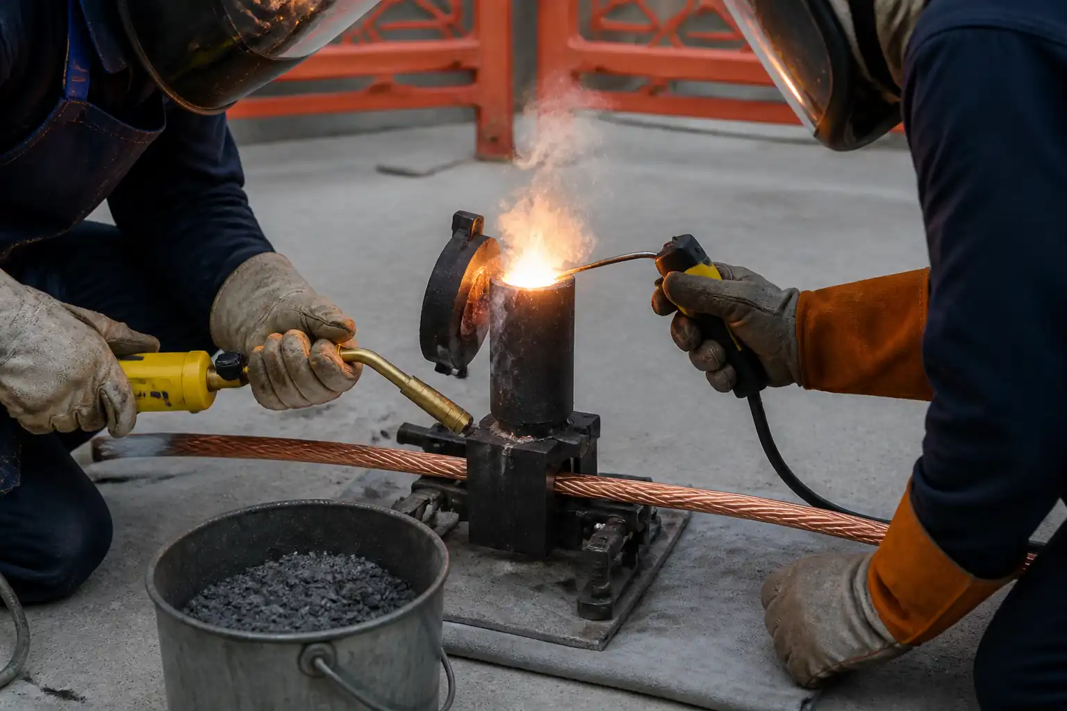
| Exothermic/mechanical joints | Visual + sample resistance check | Sound joint; resistance ≤0.1 Ω [Benchmark – Verify] | QA/QC | Joint log |
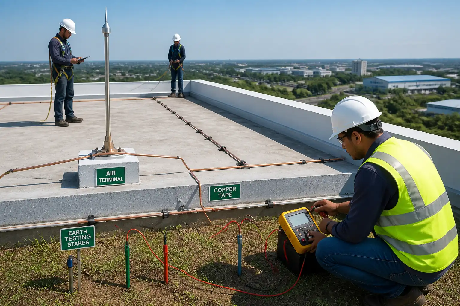
| Initial earth resistance (per electrode/system) | 3-point fall-of-potential | ≤10 Ω electrode typical; as specified [Verify] | Tester + QA/QC | Earth test report |
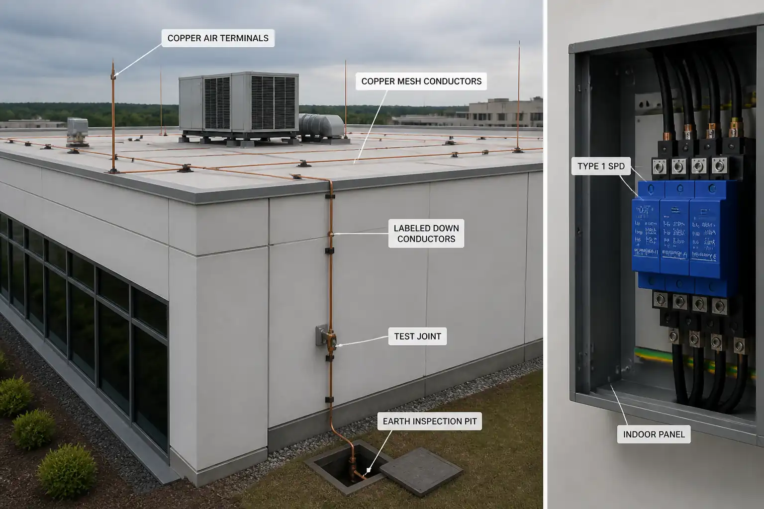
| Air terminals installation | Geometry vs. rolling sphere/mesh | Full coverage per class I–IV design | LPS Specialist + QA/QC | Air terminal ITR |
| Down conductors and test points | Continuity 200 mA; bend radius; spacing | Radii ≥8× thickness; spacing per design; test joints at 1.5–1.8 m AGL | LPS Specialist + QA/QC | Down conductor ITR |
| Equipotential bonding (services/steel) | Continuity 200 mA; visual | Resistance at joint ≤0.05 Ω [Benchmark – Verify]; correct clamps/materials | Electrician + QA/QC | Bonding ITR |
| SPD installation | Ratings (Uc, In/Imax, Up), polarity, lead length ≤0.5 m total where practicable, OCPD/back-up | Matches schedule and vendor data; indicators OK | Electrician + QA/QC | SPD checklist |
| Pre-closure inspection of test links | Visual + sample resistance | All remedials closed; authorization to proceed | QA/QC + Engineer/Client | Hold point release |
| Final connectivity and impedance test | Continuity per path; optional DLRO 10 A on main bonds [Verify] | Continuity confirmed; resistance consistent with design; joints ≤0.1 Ω [Benchmark – Verify] | QA/QC + Third-Party (if specified) | Final continuity/impedance report |
| Final overall earth resistance | 3-point test; clamp-on verification if applicable | Within project target (e.g., ≤1–5 Ω) [Verify] | Tester + QA/QC | Final earth test report |
| Documentation and handover | N/A | All ITRs, test certificates, as-builts complete | PM/QA | Handover file |
This table is a read-only public reference. Download the PDF or Excel version, or customize this ITP to edit it for your project.
Frequently asked questions
Related method statement
This Inspection and Test Plan is associated with the Method Statement – Lightning Protection System (LPS) Installation, Bonding, Surge Protection, and Testing method statement, which describes the step-by-step construction sequence, resources, materials, equipment, safety controls, and environmental controls for this activity.
View the Method Statement – Lightning Protection System (LPS) Installation, Bonding, Surge Protection, and Testing method statement →Continue with related inspection, method statement, article, and checklist resources.