
Method Statement: Vibro-Replacement Stone Columns (Bottom-Feed) for Weak Cohesive Soils – Method Statement
AI-assisted method statement with matching ITP, PDF download, and Excel export.
More than a static template
Unlike a downloadable Word or PDF template, this method statement is an AI-assisted editable starting point connected directly to a matching Inspection and Test Plan. Every section is structured, project-adaptable, and ready to export.
- AI-assisted drafting — Customize every section with AI for your specific project scope.
- Linked ITP — A matching inspection and test plan is generated alongside the method statement.
- Multiple export formats — Download as a formatted PDF or editable Excel spreadsheet.
- Editable starting point, not a final document — Review, verify, and adjust all content against your project requirements before use.
Static template vs. Quollnet workflow
| Feature | Static template | Quollnet |
|---|---|---|
| Project-specific content | Manual fill-in required | AI-assisted customization |
| Linked ITP | Separate document, no link | Matching ITP included |
| Export formats | Usually PDF only | PDF and Excel |
| Structured sections | Free-form layout | 13 standardized sections |
| Saved to your account | Local file only | Cloud-saved, reusable |
| Content accuracy | You verify everything | AI-assisted, you still verify |
| Cost | Often free but time-intensive | Free to customize and download |
What you can customize
When you save this method statement to your account, every section becomes editable. The following 13 sections are included:
- Scope — Defines the activity and its boundaries.
- References — Standards, specifications, and drawings.
- Responsibilities — Roles and accountabilities.
- Resources — Labour, plant, and equipment summary.
- Materials — Materials and compliance requirements.
- Equipment — Tools and equipment details.
- Prerequisites — Hold points and pre-conditions.
- Method sequence — Step-by-step construction sequence.
- Safety controls — HSE risk controls and PPE.
- Environmental controls — Environmental mitigation measures.
- QA/QC — Quality inspection and test requirements.
- ITP — Inspection and Test Plan table (has its own page).
- Attachments — Referenced drawings and documentation.
Why this method statement is used
This method statement is used to define and communicate the approved procedure for carrying out method statement: vibro-replacement stone columns (bottom-feed) for weak cohesive soils on site. It ensures the work is planned in advance, the correct resources and controls are in place, and all personnel understand responsibilities, sequence, quality requirements, and safety controls before work begins. It aligns site execution with the documented scope and acceptance expectations.
Who uses this method statement
This method statement is used by contractors, site supervisors, project engineers, QA/QC engineers, HSE officers, consultants, and client representatives. It serves as a shared reference for planning, execution, supervision, inspection, and approval of the activity on site.
When it is prepared and submitted
The method statement is prepared before the work activity starts and submitted as part of the pre-construction documentation package for review and approval.
Who reviews or approves it
The method statement is usually submitted to the client representative, consultant, resident engineer, or project management consultant for review and approval before the work commences.
Important approval note
This method statement is an AI-assisted editable starting point, not a pre-approved document. Before use on any project, all content must be reviewed and approved by the relevant parties (superintendent, principal contractor, or client representative) in accordance with your contract and project quality plan.
For example: if your specification requires a departure from a referenced standard, that departure must be documented and approved separately — this method statement will not capture that automatically. Always verify against your applicable drawings, specifications, and regulatory requirements.
Method statement content
Scope
Purpose
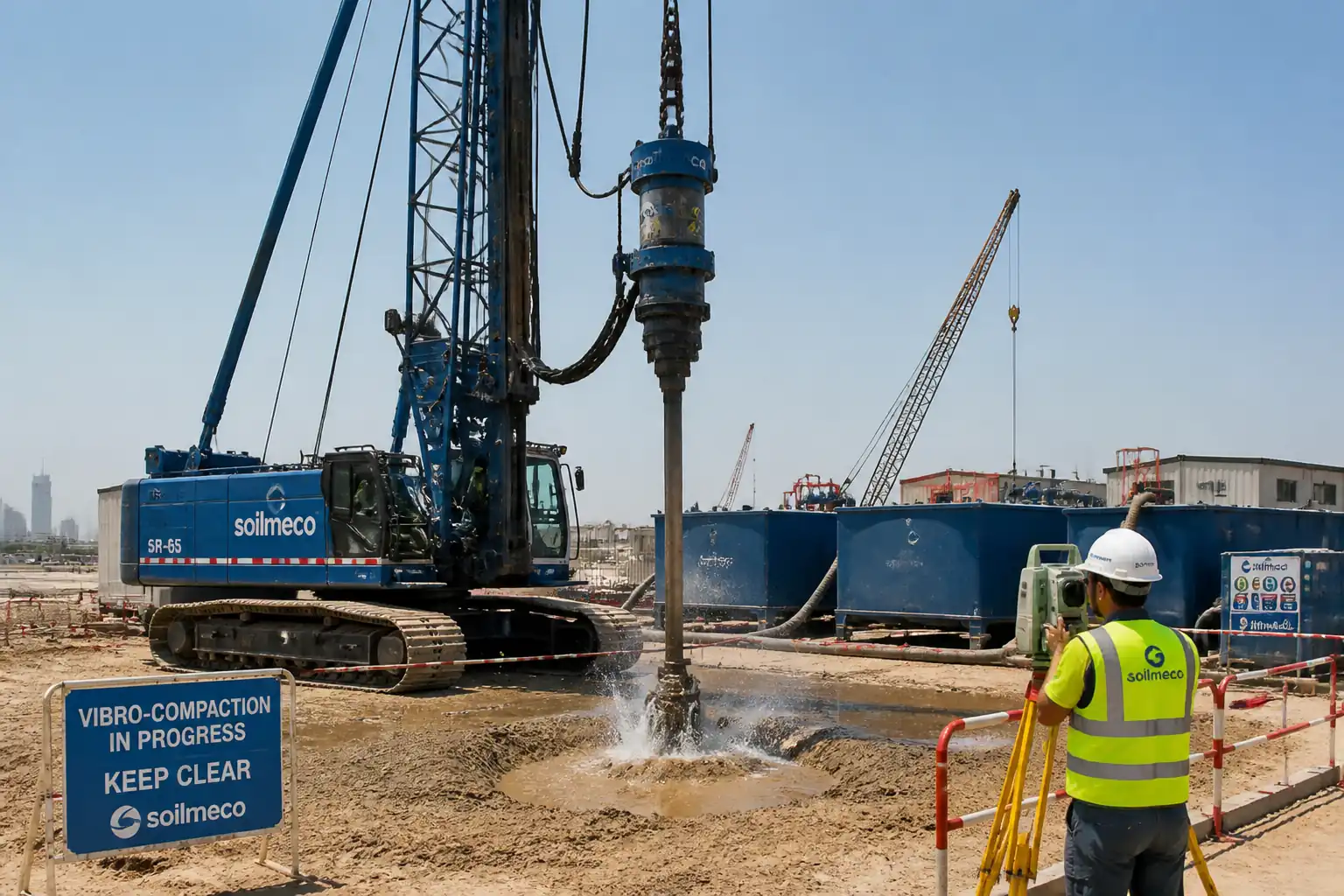
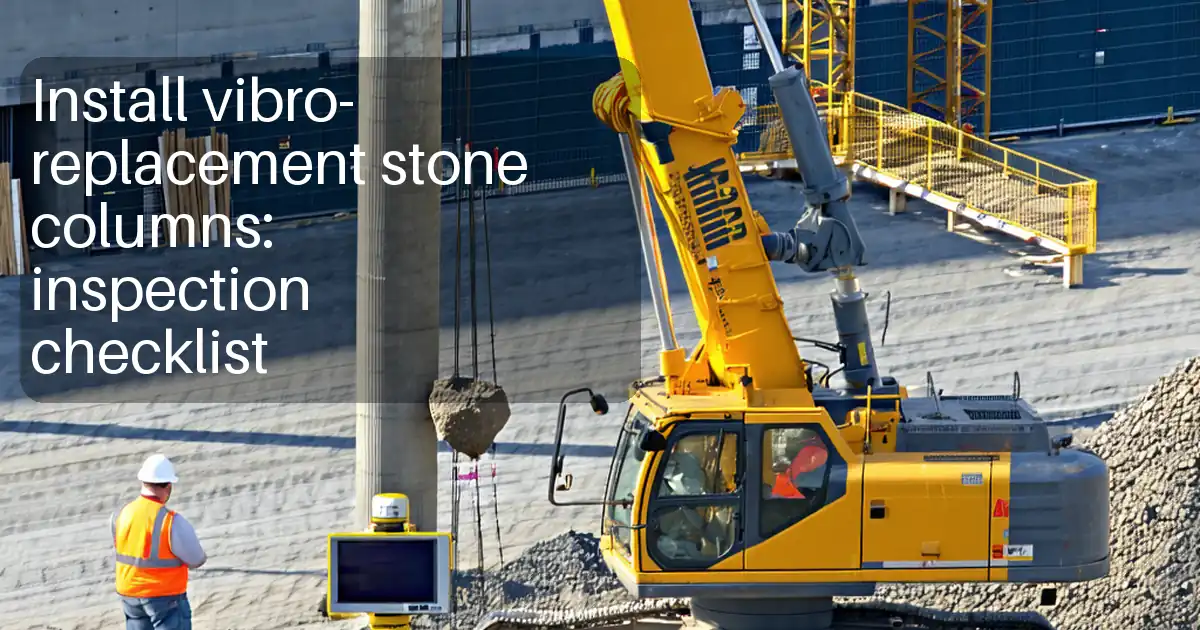
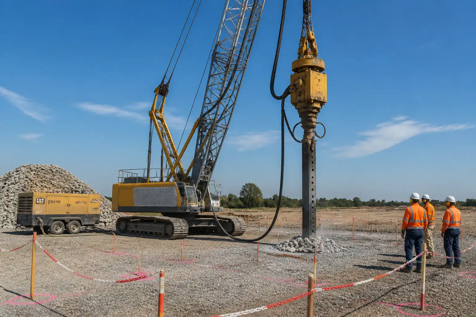
This method statement defines the procedure to install vibro-replacement (stone columns) using the bottom-feed dry method to improve bearing capacity and reduce settlement in weak cohesive soils. It covers setting out, platform preparation, production installation, execution monitoring, backfilling and compaction, tolerances, verification testing, QA/QC, and HSE controls.
Extent of Works
- Formation of a working platform for tracked crane/vibro rig over treatment area.
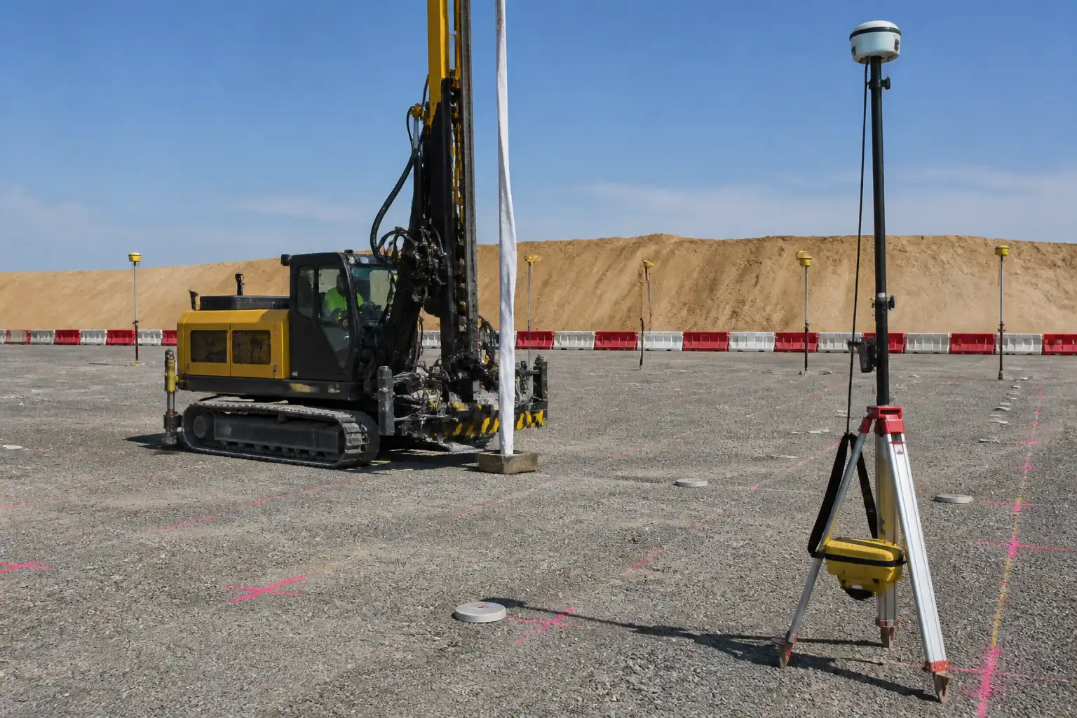
- Setting out of stone column grid per approved IFC drawings.
- Installation of stone columns to design depth/termination criteria using a bottom-feed vibroflot.
- Backfilling with graded crushed stone in controlled lifts and densification by vibro-compaction.
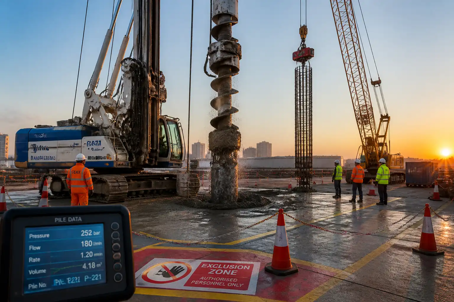
- Execution monitoring (penetration rates, current/amp draw, lift thickness, stone consumption, time-at-depth) and as-built records.
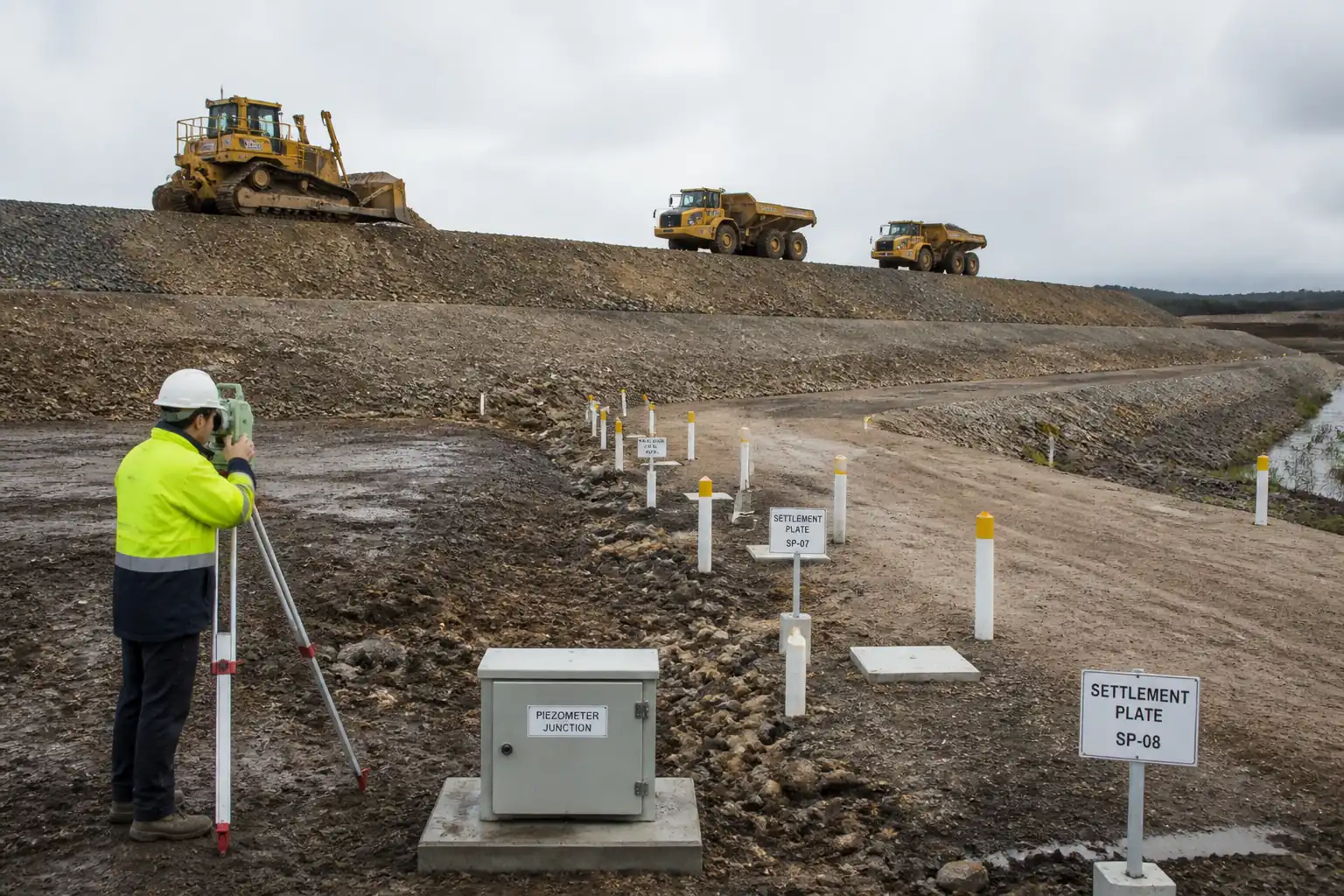
- Verification via in-situ tests (e.g., CPT/SPT, plate load tests) and compliance checks.
Out of Scope
- Wet top-feed method, slurry generation/management, and cementitious columns (not applicable to this procedure).
Key Performance Targets [Verify per project specifications]
- Column diameter (nominal): 0.8–1.2 m depending on soil and energy input.
- Layout tolerance: ≤ ±100 mm at ground level; verticality deviation ≤ 1:20.
- Termination depth tolerance: ±0.3 m from design unless refusal criteria reached.
- Stone consumption: typically 1.0–1.8 m³ per meter of column (soil dependent).
- Lift thickness: 0.4–0.6 m compacted per pass.
- Plate load test settlement at 1.0× service load: typically ≤ 25 mm; at 1.5× service load: no failure and rebound observed [Verify].
- CPT qc improvement factor in treated zones: typical 1.5–2.5× baseline in target strata [Verify].
Method Constraints
- Bottom-feed dry method selected to minimize spoil generation and groundwater turbidity in cohesive soils.
- Pre-boring may be used locally to penetrate stiff crust or obstructions as approved by the Engineer.
References
| Document Type | Reference / Number | Revision | Notes |
|---|---|---|---|
| Standard | BS EN 1997-1/2 | Latest [Verify] | |
| Standard | BS 8004 | Latest [Verify] | |
| Guideline | EFFC/DFI Vibro Stone Columns | 2016 or latest [Verify] | |
| Standards | ASTM C136, C131, C88, C295 | Latest [Verify] | |
| Standards | ASTM D5778, D1586, D1194; BS 1377-9 | Latest [Verify] | |
| Guidance | BRE BR470 | Latest [Verify] | |
| Standards | ISO 9001/14001/45001 | Latest [Verify] |
Responsibilities
| Role | Responsibility | Name / Party |
|---|---|---|
| PM | Project Manager | Contractor |
| Geotech | Geotechnical Lead Engineer | Contractor |
| SE | Site Engineer | Contractor |
| Survey | Land Surveyor | Contractor |
| Foreman | Vibro Foreman | Specialist Subcontractor |
| QA/QC | QA/QC Engineer | Contractor |
| HSE | HSE Officer | Contractor |
| Third Party | Testing Agency | Independent |
Resources
| Resource Type | Description | Quantity | Remarks |
|---|---|---|---|
| Manpower | Vibro foreman, rig operator, banksman/slinger, 2x general operatives. | 1 crew/rig | |
| Manpower | Senior surveyor + assistant, equipped for control and as-built. | 1 team | |
| Manpower | QA/QC engineer + technician for continuous monitoring and testing coordination. | 1 team |
Materials
| Material | Specification / Grade | Quantity | Remarks |
|---|---|---|---|
| Crushed stone | Project Spec Section [Verify] | As per BOQ + 5–10% wastage [Verify] | |
| Type 1/Granular Material [Verify] | BRE BR470 design output | As required by platform design | |
| Non-woven PP/PE | Project Spec [Verify] | As per drawings | |
| Stakes/paint | As required |
Equipment
| Equipment | Capacity / Type | Quantity | Inspection Required |
|---|---|---|---|
| Vibroflot | 1 per production rig | ||
| Crawler crane 60–100 t | Boom as required | 1 per rig | |
| Compressor | 1 per rig | ||
| Loader | 1 | ||
| Survey kit | As required | ||
| Logger | 1 per rig | ||
| Lighting towers, generator | As required |
Prerequisites
Approvals and Documentation
- Approved IFC drawings, geotechnical design report, and this Method Statement with ITP.
- Risk Assessment/Method Statement (RAMS) approved; permits to work including lifting permit, hot work (if welding), confined space (if applicable), and night-work permit [Verify per project HSE plan and local regulations].
- Pre-construction meeting with Engineer to confirm termination criteria, test plan, and hold points.
Site Preparation
- Utility clearance: review as-built records, conduct EML/GPR scanning, potholing where risk exists; obtain No-Objection/clearance certificates.
- Working platform: design by Temporary Works Engineer per BRE BR470; install geotextile (if specified) and compact granular platform to required stiffness and thickness; certify platform before rig entry.
- Access/egress and exclusion zones established; crane mats if required.
- Baseline testing: pre-treatment CPT/SPT at representative locations to document initial ground conditions [as per design test plan].
Materials & Equipment Readiness
- Stone aggregate source approved; stockpiles on clean, drained, segregated pads; moisture within target (surface dry).
- Calibration of data logger, depth encoder, and verification of current/amp sensors; compressor output check.
- Lifting plan, rigging study, and crane duty checks approved.
Trials
- Construct trial columns (minimum 2–3) to optimize lift thickness, air flow, stone size, energy input, and stone consumption. Update parameters and submit trial report for Engineer’s approval prior to full production.
Method Sequence
| Step | Activity | Description | Responsibility | Inspection / Hold Point |
|---|---|---|---|---|
| 1 | Control survey and layout staking | Establish grid coordinates from control; mark each column with stake/paint; verify offsets and RLs. | Surveyor | Witness point (Engineer) |
| 2 | Working platform verification | Inspect bearing capacity, thickness, drainage, level, geotextile (if any). Certify platform ready for plant. | Temporary Works Engineer / Site Engineer | Hold point (Engineer approval) |
| 3 | Trial columns | Install 2–3 trial columns to confirm penetration method, lift thickness (0.4–0.6 m), stone consumption (benchmark 1.0–1.8 m³/m), energy input, and termination criteria. | Vibro Foreman / Geotechnical Engineer | Hold point (Engineer review) |
| 4 | Pre-boring (if required) | Where stiff crust/obstruction exists, pre-bore to diameter 250–450 mm to ease penetration; backfill bore with stone or re-compacted soils before vibro insertion. | Site Engineer / Vibro Foreman | Inspection point |
| 5 | Probe penetration (vibroflot) | Position vibro over mark; start vibration; apply downthrust to penetrate to design depth. Use air assist to clear and maintain annulus. Control penetration rate. | Vibro Operator | Continuous monitoring |
| 6 | Bottom-feed stone charging | Open stone gate to feed graded stone through tremie to tip; ensure continuous stone column formation without segregation. | Vibro Operator / Loader Operator | Visual and parameter monitoring |
| 7 | Compaction and stemming (lift-by-lift) | Raise vibro 0.4–0.6 m; hold and compact for 30–60 s; monitor current rise (indicative of densification). Repeat to surface, forming a continuous column. | Vibro Operator | Continuous monitoring |
| 8 | Top-up and surface treatment | Form a slight stone dome (50–100 mm) at surface to counter post-vibration settlement; trim flush as directed. | Vibro Foreman | Inspection point |
| 9 | As-built survey | Survey top center and RL of each column; record any deviations and remarks. | Surveyor | Witness point |
| 10 | Verification testing | Conduct CPT/SPT in treated zones and plate load tests on selected locations/rafts as per ITP. | QA/QC Engineer / Third-Party | Hold point for test setup |
| 11 | Area release | On completion of all tests and acceptance of records, release area for overlying works (raft, footing, slab). | Project Manager / Engineer | Hold point (final) |
Health, Safety and Environmental Controls – Safety
Task-Specific Hazards and Controls
1) Hazard: Working platform failure under crane/rig
- Likely consequence: Plant overturn; fatality; equipment damage.
- Engineering/procedural control: Temporary Works design per BRE BR470; platform inspection and certification; defined plant routes; exclusion zones around rig radius + 5 m.
- Required PPE: Safety boots, hard hat, hi-vis, gloves; eye protection.
- Collective preventive measure: Edge protection at drops; barriers; banksman control; load-spread mats if required.
- Inspection/permit/supervision: Daily platform inspection; pre-use plant checks; lifting permit; competent Temporary Works Coordinator sign-off [Verify per project HSE plan and local regulations].
2) Hazard: Underground services strike during probing/pre-boring
- Likely consequence: Electrocution, gas leak, flooding, service outage.
- Engineering/procedural control: Utility survey (EML/GPR), permit-to-dig, trial holes/potholing, set exclusion offsets, depth constraints near utilities.
- Required PPE: Dielectric gloves when necessary, standard PPE; gas detector when gas risk.
- Collective preventive measure: Physical barriers/marking of services; supervised digging.
- Inspection/permit/supervision: Permit-to-dig; supervisor sign-off; utility owner coordination.
3) Hazard: Lifting operations with suspended vibroflot
- Likely consequence: Load drop; struck-by; crush injuries.
- Engineering/procedural control: Lift plan; certified crane/operator/rigger; tag lines; no work under suspended loads; wind limit per crane chart (e.g., stop > 9–12 m/s) [Verify].
- Required PPE: Helmet with chin strap, gloves, safety boots, hi-vis.
- Collective preventive measure: Exclusion zone; radios; banksman.
- Inspection/permit/supervision: Lifting permit; daily crane inspection; weekly thorough checks per regulation.
4) Hazard: Compressed air and high-pressure hoses (bottom-feed)
- Likely consequence: Hose whip; injection injury; noise exposure.
- Engineering/procedural control: Pressure-rated hoses with whip checks; secure couplings; pressure relief; controlled start-up/shutdown; hose inspections.
- Required PPE: Eye/face protection, hearing protection (SNR per noise survey), gloves.
- Collective preventive measure: Hose guards; barriers around feed area.
- Inspection/permit/supervision: Pressure system inspection logs; competent operator; permit as required.
5) Hazard: Open craters/unstable ground around probe point
- Likely consequence: Trips/falls; engulfment in soft spots.
- Engineering/procedural control: Maintain tidy platform, backfill and level depressions promptly; demarcate active points; restrict access.
- Required PPE: Safety boots with ankle support; hi-vis.
- Collective preventive measure: Barriers and signage; spotters at night.
- Inspection/permit/supervision: Supervisor patrols; night lighting checks.
6) Hazard: Noise and vibration
- Likely consequence: Hearing loss; nuisance; potential impact on sensitive structures.
- Engineering/procedural control: Noise/vibration monitoring plan; maintain equipment; set working hours; install temporary acoustic screens if required; pre-condition surveys of adjacent assets.
- Required PPE: Hearing protection; standard PPE.
- Collective preventive measure: Perimeter notices; community liaison for schedule.
- Inspection/permit/supervision: Monitoring records; compliance with local limits [Verify].
7) Hazard: Manual handling and pinch points (stone handling)
- Likely consequence: Strains; crush injuries.
- Engineering/procedural control: Mechanical handling with loader; safe zones around hoppers; no hand-feeding when plant is live; training.
- Required PPE: Gloves, safety boots.
- Collective preventive measure: Physical guarding on hoppers; lock-out/tag-out for maintenance.
- Inspection/permit/supervision: Supervisor checks; maintenance permits.
8) Hazard: Electrical hazards from vibro power unit
- Likely consequence: Electric shock; fire.
- Engineering/procedural control: IP-rated enclosures; RCD protection; cable management; earth leakage monitoring; lockable isolators.
- Required PPE: Electrical-rated gloves when performing checks; otherwise standard PPE.
- Collective preventive measure: Barriers around power skids; fire extinguishers (CO₂/dry powder).
- Inspection/permit/supervision: Electrical inspection/tagging; competent electrician; hot works permit if cutting/welding.
9) Hazard: Traffic interface and reversing plant
- Likely consequence: Vehicle-person collision.
- Engineering/procedural control: One-way routes; spotters; reversing alarms/cameras; segregation of pedestrian walkways.
- Required PPE: Hi-vis (Class 3), steel-toe boots, helmet.
- Collective preventive measure: Physical barriers; marshals.
- Inspection/permit/supervision: Traffic management plan sign-off; daily checks.
10) Hazard: Night/low visibility operations
- Likely consequence: Increased incident likelihood.
- Engineering/procedural control: Task lighting ≥ 50 lux; reflective PPE; enhanced supervision.
- Required PPE: High-reflectivity vests, headlamps as needed.
- Collective preventive measure: Light towers; backup power.
- Inspection/permit/supervision: Night work permit; lighting inspection logs.
Health, Safety and Environmental Controls – Environmental
Environmental Risks and Controls
- Noise and Vibration
- Consequence: Disturbance to receptors; complaints; regulatory non-compliance.
- Control: Baseline survey; continuous/spot monitoring at site boundary; schedule high-noise activities daytime; maintain rigs; temporary acoustic screens where required. [Verify per local limits]
-
Records: Noise/vibration logs; community liaison record.
-
Dust from aggregate handling
- Consequence: Air quality degradation; nuisance; health impacts.
- Control: Keep stone slightly damp if needed; water spray on stockpiles/haul roads; cover loads; 15 km/h site speed limit; wheel wash if required.
-
Records: Dust suppression logs.
-
Spills and contaminated runoff
- Consequence: Soil/groundwater pollution.
- Control: Spill kits at fueling/power skids; drip trays; double-walled fuel tanks; refuel in designated bunded area; train operators.
-
Records: Spill register; inspection checklists.
-
Groundwater turbidity
- Consequence: Water quality impact off-site.
- Control: Bottom-feed dry method selected; avoid water flushing; if dewatering is required locally, discharge via settlement tank; no direct discharge to drains without permit.
-
Records: Discharge permits; turbidity logs if applicable.
-
Waste management
- Consequence: Littering; non-compliance.
- Control: Segregated skips; recycle stone spillage; licensed carriers; maintain waste transfer notes.
-
Records: Waste transfer documentation.
-
Ecology and heritage
- Consequence: Habitat or archaeological disturbance.
- Control: Buffer zones; ecological/archaeological watch if required; stop-work protocol upon discovery.
-
Records: Watch brief reports.
-
Energy and carbon
- Consequence: Excess emissions.
- Control: Engine idling policy; optimize rig utilization; use Tier-compliant plant; consider HVO/diesel alternative if approved.
- Records: Fuel logs, emissions reports.
Quality Assurance and Quality Control
General
- Quality system per ISO 9001; inspection and testing per approved ITP; all measuring devices calibrated and within validity.
Execution Monitoring Parameters (recorded per column)
- Coordinates and ID; date/time; operator; vibro type.
- Penetration depth (m); termination reason (design/refusal).
- Penetration rate vs depth.
- Electrical current/energy draw trends (or hydraulic pressure) during penetration and compaction.
- Lift count and individual lift thickness (target 0.4–0.6 m).
- Compaction hold time per lift (target 30–60 s) and time-at-depth.
- Stone feed cycles and total stone consumption (target vs actual; tolerance +10/−5% unless otherwise specified [Verify]).
- Top level RL and final dome height.
Acceptance Criteria [Verify per project specifications]
- Position tolerance: ≤ ±100 mm at platform level.
- Verticality: deviation ≤ 1:20.
- Depth: design depth ±0.3 m unless earlier refusal per approved criterion.
- Stone: grading/quality per Material specification; certificates on lot basis (every 500 t or per week, whichever earlier).
- Lift thickness: 0.4–0.6 m compacted; no skipped lifts.
- Energy trend: evidence of densification (increasing current/pressure) at each lift.
- Stone consumption: within +10/−5% of theoretical consumption after trials, unless justified by logs and ground variability.
- Surface level: top within +50/−20 mm of platform RL.
Testing Regime (typical)
- Aggregates: Sieve, LA Abrasion, Soundness – frequency: 1 per source and then 1 per 500 t [Verify].
- CPT/SPT: Post-improvement at representative grid (e.g., 1 per 1,000–2,000 m² or as designed) [Verify].
- Plate Load Tests: On selected locations (e.g., 1 per 50–100 columns or per structure bay) to 1.5× service load [Verify].
- Platform tests: As required by TWD (e.g., LFWD/plate).
Nonconformance and Corrective Measures
- Out-of-tolerance position: Engineer review; add infill column(s) if spacing critical.
- Insufficient depth/energy: Re-enter and re-compact; or install adjacent supplementary column as directed.
- Low stone consumption/poor energy trend: Additional compaction passes; adjust lift thickness; increase stone size or air flow per Engineer-approved parameter change.
- Failed verification test: Root cause analysis; increase treatment density (reduce spacing), additional columns, or rework; repeat testing until acceptance.
Records and Handover
- Daily production summary, on-rig monitoring plots, delivery tickets, aggregate test reports, as-built survey, verification test reports, NCR/CAR closure, final acceptance certificate.
Attachments
Attachments / Appendices (typical)
- Appendix A: Lifting Plan and Rigging Study
- Appendix B: Working Platform Design Certificate and Inspection Checklist
- Appendix C: Trial Column Report (parameters, logs, plots)
- Appendix D: Daily Production Log Template (penetration, lifts, energy, consumption)
- Appendix E: Aggregate Test Certificates and Sampling Plan
- Appendix F: Verification Testing Plan (CPT/SPT/PLT locations) and Reports
- Appendix G: As-Built Coordinate Register and Drawings (CSV/PDF)
- Appendix H: HSE RAMS, Permits, Toolbox Talk Records
- Appendix I: Calibration Certificates (logger, depth encoder, survey equipment)
- Appendix J: NCR/CAR Register and Close-out Evidence
This content is a read-only public reference. Download or customize to get an editable version.
ITP preview
The first inspection activities from the linked ITP for Method Statement: Vibro-Replacement Stone Columns (Bottom-Feed) for Weak Cohesive Soils:
| Activity | Inspection / Test | Acceptance Criteria | Responsibility | Record |
|---|---|---|---|---|
| Method Statement & ITP approval | Document review/approval | Approved documents issued for construction. | Project Manager / Engineer | Approved MS & ITP, distribution sheet |
| Pre-start HSE and permits | RAMS, permits, TBT records | Permits in place; TBT conducted; controls implemented. | HSE Officer / PM | Signed permits, TBT attendance |
| Working platform certification | Visual + LFWD/plate (if required) | Meets TWD; certificate issued prior to plant entry. | Temporary Works Engineer / Engineer | Platform certificate, test results |
Showing 3 of 15 inspection activities. View full ITP →
Related Inspection and Test Plan
An Inspection and Test Plan (ITP) is available for Method Statement: Vibro-Replacement Stone Columns (Bottom-Feed) for Weak Cohesive Soils. The ITP defines the inspection activities, acceptance criteria, hold and witness points, responsible parties, and records required to verify the work described in this method statement.
View the Method Statement: Vibro-Replacement Stone Columns (Bottom-Feed) for Weak Cohesive Soils ITP →Frequently asked questions
Continue with related Quollnet resources connected to this method statement.