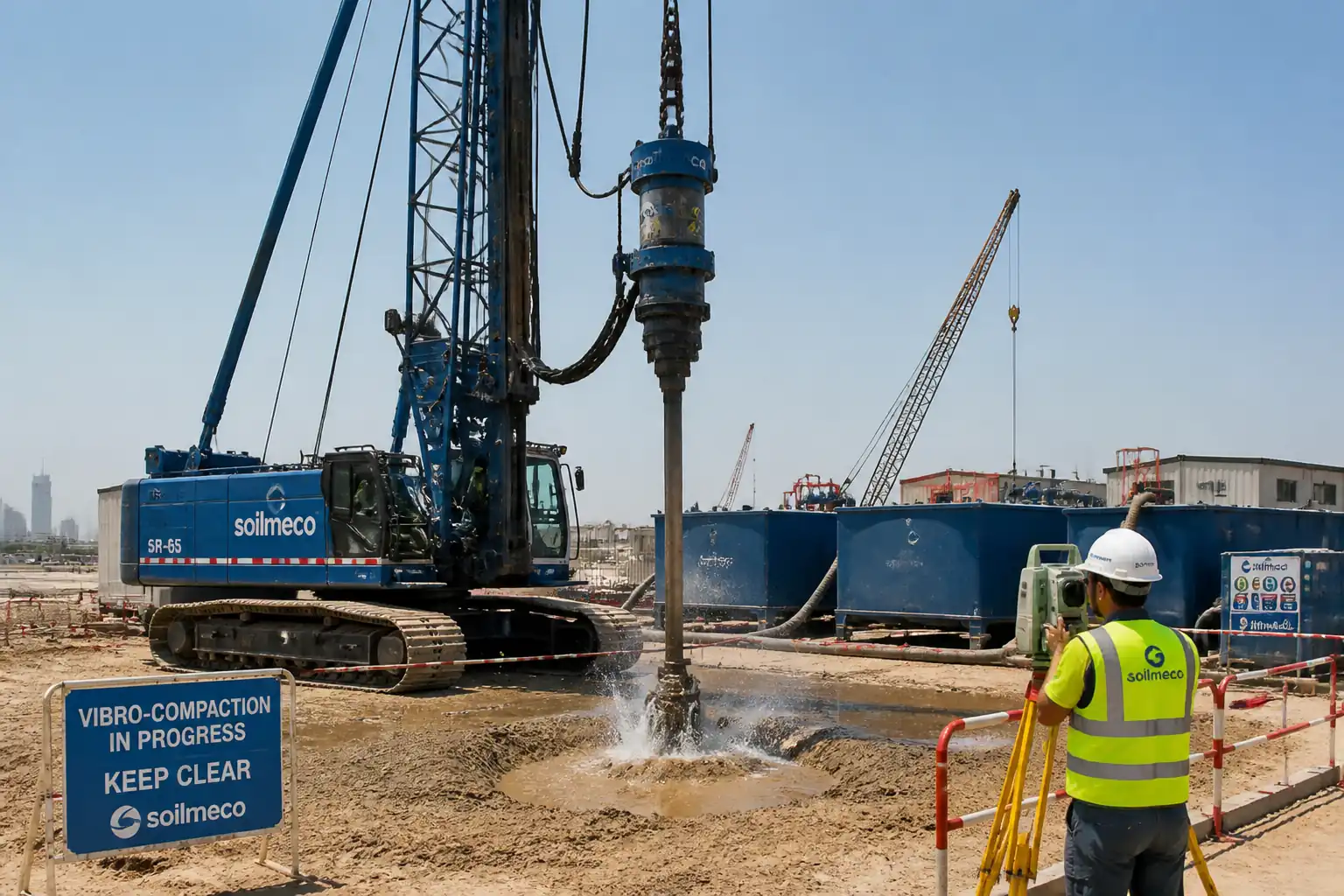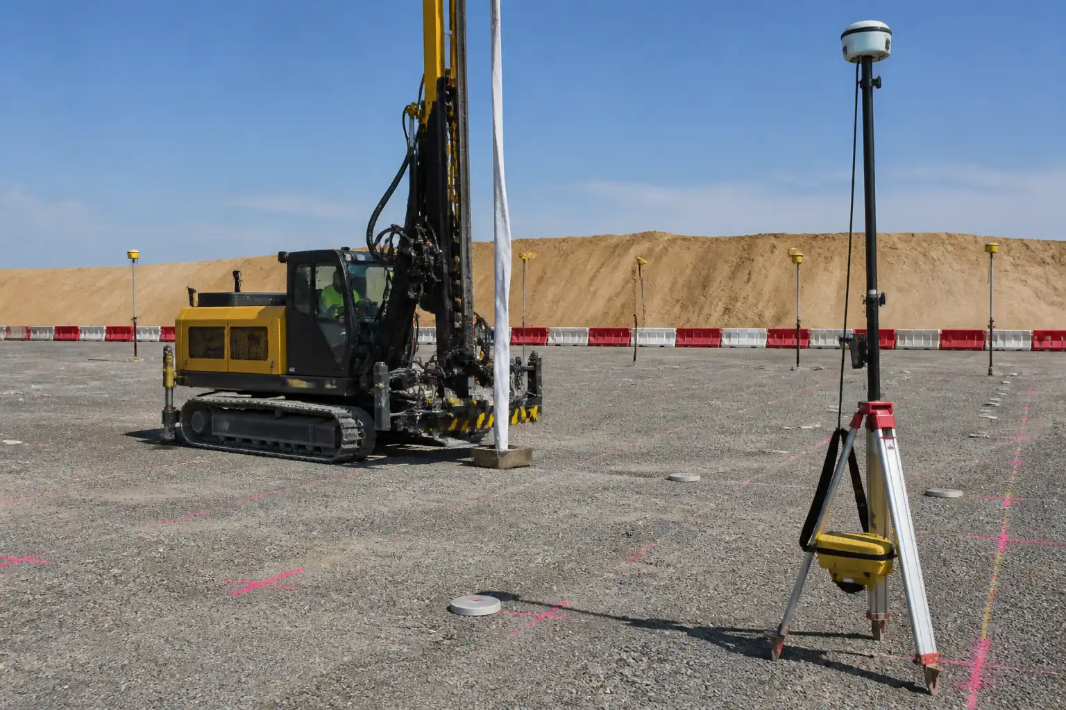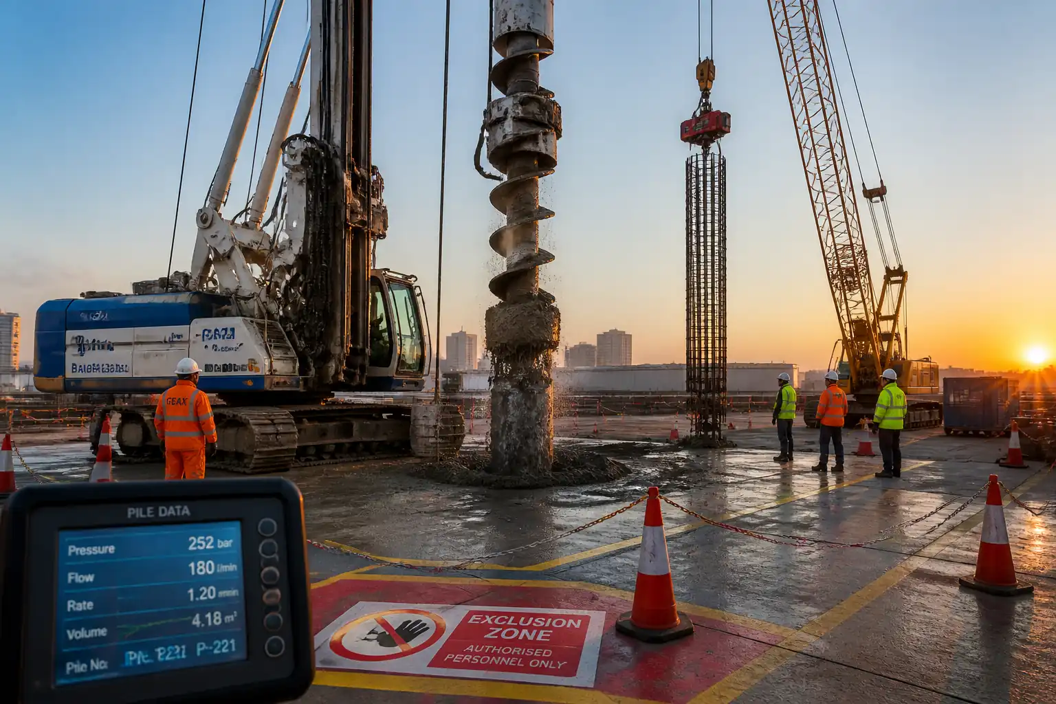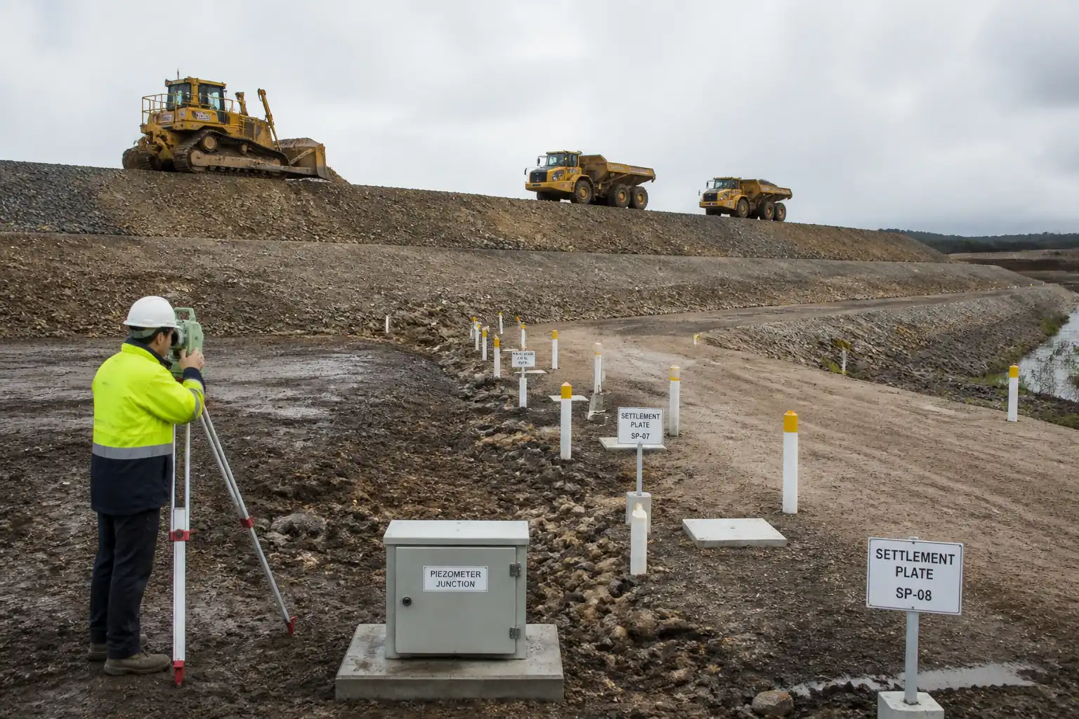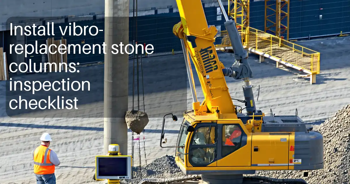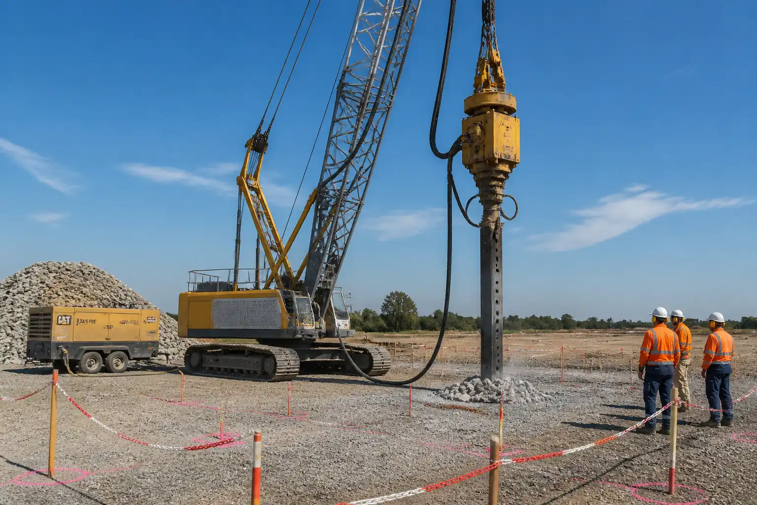

Inspection and Test Plan for Method Statement: Vibro-Replacement Stone Columns (Bottom-Feed) for Weak Cohesive Soils
AI-assisted inspection and test plan connected to a method statement, with PDF and Excel export.
More than a static template
Unlike a downloadable Word or PDF template, this ITP is an AI-assisted editable starting point directly connected to its method statement. Every inspection activity, hold point, and acceptance criterion is structured and ready to adapt to your project.
- AI-assisted customization — Tailor inspection activities and acceptance criteria to your specific project scope.
- Linked method statement — This ITP is connected to the corresponding method statement describing the work sequence.
- Multiple export formats — Download as a formatted PDF or editable Excel spreadsheet.
- Editable starting point, not a final document — Review and verify all content against your project specifications and standards before use.
What you can customize
When you save this ITP to your account, every inspection row becomes editable. You can add, remove, or modify:
- Inspection activity — Description of what is being inspected.
- Inspection type — Hold point (H), Witness point (W), Review (R), or Monitor (M).
- Responsibility — Contractor, subcontractor, engineer, or client.
- Frequency — How often the inspection occurs.
- Acceptance criteria — Referenced standard or specification requirement.
- Records — Forms, test reports, or checklists required as evidence.
Why this ITP is used
To control and verify that vibro stone columns are installed to design requirements with traceable QA/QC and safety compliance.
Who uses this inspection and test plan
Contractor site team, geotechnical engineer, QA/QC staff, HSE, and the Engineer or Employer’s Representative.
When this ITP is prepared and submitted
From pre-start through production and until final acceptance, including trials and verification tests.
Who receives or approves this ITP
The ITP is usually submitted to the client representative, consultant, resident engineer, or project management consultant for review and approval before the related work activity starts.
Inspection scope
Covers working platform, layout, aggregates, equipment calibration, penetration and compaction monitoring, stone consumption, as-built survey, and verification tests.
Typical hold, witness, and review points
Working platform certification (H), trial columns (H), first production columns (W), aggregate approval (H), CPT/PLT setups (H), final dossier (H).
Typical inspection records
Daily logs, monitoring plots, delivery tickets, calibration certs, survey as-builts, CPT/SPT/PLT reports, NCR close-outs, acceptance certificate.
Important approval note
This ITP is an AI-assisted editable starting point, not a pre-approved document. Before use on any project, all inspection activities, hold points, and acceptance criteria must be reviewed and approved by the relevant parties (superintendent, principal contractor, or client representative) in accordance with your contract and project quality plan.
Always verify acceptance criteria against your applicable drawings, specifications, and regulatory requirements. Hold points must be confirmed with the relevant authority before work proceeds past that point.
Inspection and test plan
| Activity | Inspection / Test | Acceptance Criteria | Responsibility | Record |
|---|---|---|---|---|
| Method Statement & ITP approval | Document review/approval | Approved documents issued for construction. | Project Manager / Engineer | Approved MS & ITP, distribution sheet |
| Pre-start HSE and permits | RAMS, permits, TBT records | Permits in place; TBT conducted; controls implemented. | HSE Officer / PM | Signed permits, TBT attendance |
| Working platform certification | Visual + LFWD/plate (if required) | Meets TWD; certificate issued prior to plant entry. | Temporary Works Engineer / Engineer | Platform certificate, test results |
| Survey set-out verification | Spot check of coordinates | Grid within ±100 mm tolerance. | Surveyor / Engineer | Set-out check sheet |
| Aggregate quality (incoming) | ASTM C136, C131, C88, C295 (as required) | Meets grading/quality requirements. | QA/QC Engineer | Mill/test certificates |
| Equipment calibration/condition | Logger/calibration checks; visual plant inspection | Valid calibration; plant safe and serviceable. | QA/QC Engineer / Plant | Calibration certs; pre-start checklists |
| Trial columns | On-rig monitoring; CPT/PLT as specified | Parameters and outcomes accepted for production. | Geotechnical Engineer / Engineer | Approved trial report |
| Production column penetration | Depth/time/current logs | Design depth ±0.3 m or approved refusal criteria met. | Vibro Foreman / QA/QC | Penetration logs |
| Lift-by-lift compaction | Lift thickness, time-at-depth, energy trend | Lift 0.4–0.6 m; evidence of densification at each hold. | Vibro Operator / QA/QC | Compaction logs |
| Stone consumption check | Compare actual vs theoretical | +10/−5% of target unless justified by records [Verify]. | QA/QC Engineer | Stone tally sheets |
| Top level / surface finish | Level survey | +50/−20 mm of platform RL. | Site Engineer / QA/QC | Level check report |
| As-built survey | Coordinate and RL survey | Position ≤ ±100 mm; RL within tolerance. | Surveyor / QA/QC | As-built data and drawings |
| Verification CPT/SPT | ASTM D5778 / D1586 | qc/N-value improvement per design; no weak lenses compromising performance [Verify]. | Third-Party / QA/QC | Accredited test reports |
| Plate load test (PLT) | ASTM D1194 or BS 1377-9 | Load–settlement within design limits; no shear failure at 1.5× service load [Verify]. | Third-Party / Engineer | PLT report with plots/photos |
| Final dossier and area acceptance | Document completeness review | All records approved; NCRs closed; acceptance certificate issued. | Project Manager / Engineer | Signed acceptance/release |
This table is a read-only public reference. Download the PDF or Excel version, or customize this ITP to edit it for your project.
Frequently asked questions
Related method statement
This Inspection and Test Plan is associated with the Method Statement: Vibro-Replacement Stone Columns (Bottom-Feed) for Weak Cohesive Soils method statement, which describes the step-by-step construction sequence, resources, materials, equipment, safety controls, and environmental controls for this activity.
View the Method Statement: Vibro-Replacement Stone Columns (Bottom-Feed) for Weak Cohesive Soils method statement →Continue with related inspection, method statement, article, and checklist resources.