Method Statement – Continuous Flight Auger (CFA) Piling Works – Method Statement
AI-assisted method statement with matching ITP, PDF download, and Excel export.
More than a static template
Unlike a downloadable Word or PDF template, this method statement is an AI-assisted editable starting point connected directly to a matching Inspection and Test Plan. Every section is structured, project-adaptable, and ready to export.
- AI-assisted drafting — Customize every section with AI for your specific project scope.
- Linked ITP — A matching inspection and test plan is generated alongside the method statement.
- Multiple export formats — Download as a formatted PDF or editable Excel spreadsheet.
- Editable starting point, not a final document — Review, verify, and adjust all content against your project requirements before use.
Static template vs. Quollnet workflow
| Feature | Static template | Quollnet |
|---|---|---|
| Project-specific content | Manual fill-in required | AI-assisted customization |
| Linked ITP | Separate document, no link | Matching ITP included |
| Export formats | Usually PDF only | PDF and Excel |
| Structured sections | Free-form layout | 13 standardized sections |
| Saved to your account | Local file only | Cloud-saved, reusable |
| Content accuracy | You verify everything | AI-assisted, you still verify |
| Cost | Often free but time-intensive | Free to customize and download |
What you can customize
When you save this method statement to your account, every section becomes editable. The following 13 sections are included:
- Scope — Defines the activity and its boundaries.
- References — Standards, specifications, and drawings.
- Responsibilities — Roles and accountabilities.
- Resources — Labour, plant, and equipment summary.
- Materials — Materials and compliance requirements.
- Equipment — Tools and equipment details.
- Prerequisites — Hold points and pre-conditions.
- Method sequence — Step-by-step construction sequence.
- Safety controls — HSE risk controls and PPE.
- Environmental controls — Environmental mitigation measures.
- QA/QC — Quality inspection and test requirements.
- ITP — Inspection and Test Plan table (has its own page).
- Attachments — Referenced drawings and documentation.
Why this method statement is used
This method statement is used to define and communicate the approved procedure for carrying out method statement – continuous flight auger (cfa) piling works on site. It ensures the work is planned in advance, the correct resources and controls are in place, and all personnel understand responsibilities, sequence, quality requirements, and safety controls before work begins. It aligns site execution with the documented scope and acceptance expectations.
Who uses this method statement
This method statement is used by contractors, site supervisors, project engineers, QA/QC engineers, HSE officers, consultants, and client representatives. It serves as a shared reference for planning, execution, supervision, inspection, and approval of the activity on site.
When it is prepared and submitted
The method statement is prepared before the work activity starts and submitted as part of the pre-construction documentation package for review and approval.
Who reviews or approves it
The method statement is usually submitted to the client representative, consultant, resident engineer, or project management consultant for review and approval before the work commences.
Important approval note
This method statement is an AI-assisted editable starting point, not a pre-approved document. Before use on any project, all content must be reviewed and approved by the relevant parties (superintendent, principal contractor, or client representative) in accordance with your contract and project quality plan.
For example: if your specification requires a departure from a referenced standard, that departure must be documented and approved separately — this method statement will not capture that automatically. Always verify against your applicable drawings, specifications, and regulatory requirements.
Method statement content
Scope
Overview
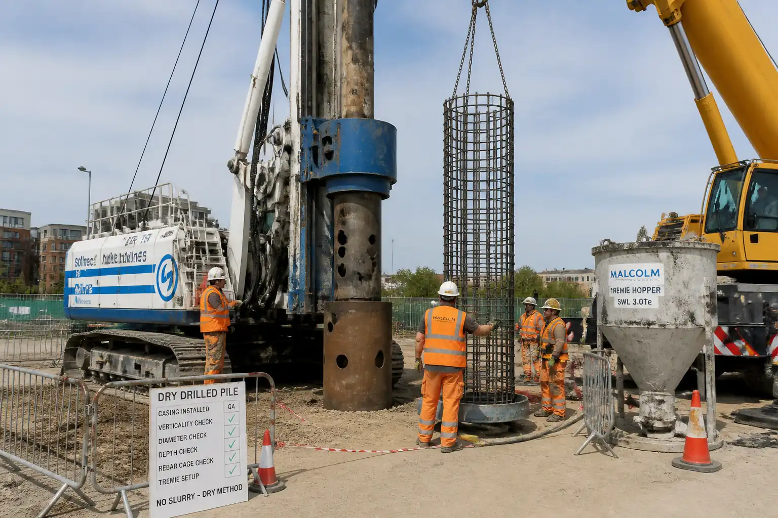
This method statement covers planning, execution, monitoring, and quality control of Continuous Flight Auger (CFA) piling works for building and infrastructure foundations. It includes setting out, platform preparation, auger drilling, continuous concrete pumping during auger extraction, automated data logging, reinforcement cage installation with vibratory equipment, tolerances, testing, and records.
Inclusions
- CFA piles of design diameters typically 400–1200 mm and lengths up to project design limits [Verify per project specifications].
- Drilling with continuous flight auger, pumping of concrete through hollow stem, and controlled auger extraction.
- Real-time monitoring and recording of depth, torque, pull-down, extraction rate, concrete pressure, flow, and volume.
- Vibratory installation of prefabricated reinforcement cages into fresh concrete.
- Pile head trimming and temporary protection.
- Concrete sampling and testing.
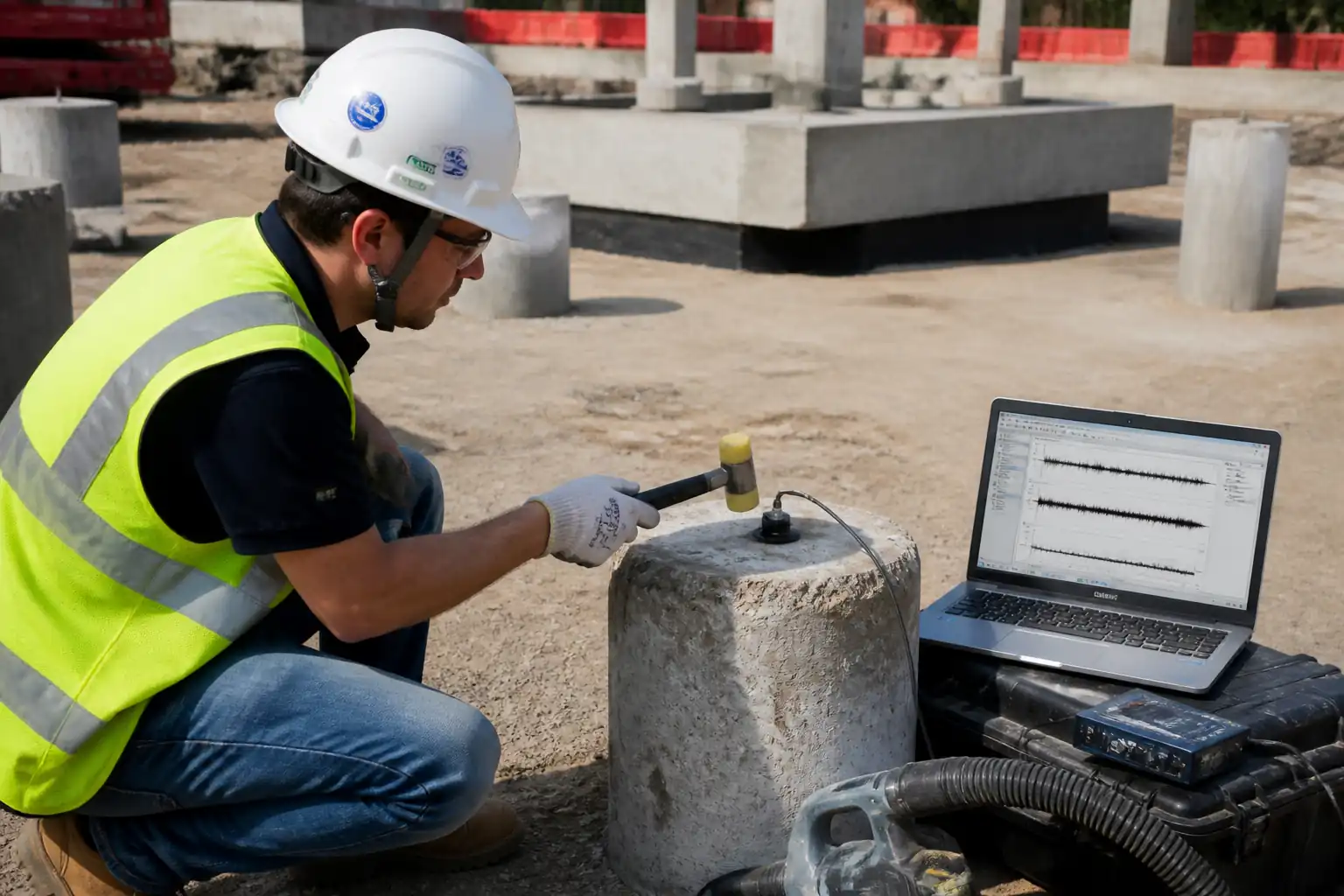
- Pile integrity testing (PIT) and load testing where specified.
Exclusions
- Permanent casings, secant/tangent pile walls (unless specified), diaphragm walls, and displacement piles other than CFA.
- Ground improvement, dewatering, or grouting unless specifically directed.
Key Performance Requirements
- Positional tolerance at cut-off: typically ±75 mm for D ≤ 750 mm; ±100 mm for D > 750 mm [Verify per project specifications].
- Verticality tolerance: not exceeding 1:100 [Verify].
- Concrete continuity: maintain positive head/pressure, target volume factor 1.10–1.35 of theoretical, subject to ground conditions [Verify].
- Concrete slump (pumpable CFA mix): typically 180 ± 20 mm or slump-flow 550–650 mm with max aggregate 20 mm [Verify].
- Maintain continuous concrete pumping pressure during auger extraction: typically 0.3–0.6 MPa at the swivel/auger head, sufficient to prevent inflow/necking [Verify].
- Cage installation into fresh concrete within target time window (e.g., ≤30–45 minutes from completion of concreting, considering admixtures and temperature) [Verify].
References
| Document Type | Reference / Number | Revision | Notes |
|---|---|---|---|
| Standard | BS EN 1536: Execution of special geotechnical works – Bored piles (includes CFA) | Primary execution standard for bored/CFA piles [Verify national annex]. | |
| Standard | EN 1997-1 (Eurocode 7) – Geotechnical design | Design principles, partial factors, testing and control. | |
| Standard | EN 206 – Concrete specification, performance, production and conformity | Concrete supply, conformity and testing. | |
| Standard | EN 12350 (Parts 1–7) – Testing fresh concrete (slump, flow, density, temperature, air) | Sampling and fresh concrete tests. | |
| Standard | EN 12390 (Parts 1–3,7) – Hardened concrete tests (making, curing, compressive strength) | Cube/cylinder preparation and compressive strength. | |
| Standard/Guide | ACI 336.3R – Guide to Design and Construction of Auger Cast-in-Place Piles | US practice reference for ACIP/CFA techniques and QC. | |
| Standard | ASTM D5882 – Low Strain Integrity Testing of Deep Foundations | PIT for integrity assessment (where specified). | |
| Standard | EN ISO 22477-1 – Testing of geotechnical structures, Part 1: Vertical load tests on piles | Static load testing (maintained load/quick tests). | |
| Guidance | ICE Specification for Piling and Embedded Retaining Walls (SPERW), latest ed. | Execution and tolerances guidance [Verify project edition]. | |
| Standard | BS 5975 – Temporary works procedures and the permissible stress design of falsework | Temporary works design and control of piling platform and lifting operations. |
Responsibilities
| Role | Responsibility | Name / Party |
|---|---|---|
| PM | Project Manager | Contractor |
| SM/CM | Site Manager / Construction Manager | Contractor |
| TWC | Temporary Works Coordinator (TWC) | Contractor |
| Supervisor | Piling Supervisor | Specialist Piling Subcontractor |
| Operator | Rig Operator | Specialist Piling Subcontractor |
| Supplier Rep | Concrete Pump/Batching Representative | Ready-Mix Supplier |
| QA/QC | QA/QC Engineer | Contractor |
| Surveyor | Land Surveyor | Contractor |
| HSE | HSE Manager/Officer | Contractor |
| Client Rep | Client/Engineer’s Representative | Client/Engineer |
Resources
| Resource Type | Description | Quantity | Remarks |
|---|---|---|---|
| Labour | 1 Supervisor, 1 Rig Operator, 1 Pump Operator, 2 Banksmen/Slingers, 2 Steel Fixers, 1 QA/QC Technician, 1 General Operative per rig | ||
| Labour | 1 Surveyor + 1 Assistant (as required) | ||
| Service | Continuous supply 20–60 m³/h depending on pile size [Verify] |
Materials
| Material | Specification / Grade | Quantity | Remarks |
|---|---|---|---|
| Ready-Mix Concrete for CFA | Strength class typically C30/37 or as designed; max aggregate 20 mm; target slump 180 ± 20 mm or slump-flow 550–650 mm; w/c ≤ 0.55; Chloride class per exposure [Verify]. | ||
| Reinforcement Steel (Cage) | Grade per design (e.g., B500B/B500C); cover spacers (non-absorbent) to achieve nominal cover (typically 50–75 mm) [Verify]. | ||
| Spacers and Centralizers | To maintain concentricity and specified cover during vibratory insertion. |
Equipment
| Equipment | Capacity / Type | Quantity | Inspection Required |
|---|---|---|---|
| CFA Rig & Hollow-Stem Auger | Torque typically 100–300 kNm; auger diameters 400–1200 mm [Verify] | Daily pre-use, weekly inspection, service records | |
| Concrete Pump & Delivery System | Flow 20–60 m³/h; working pressure 6–10 bar (0.6–1.0 MPa) [Verify] | Pressure test and certification within 6 months; hose inspection each shift | |
| Cage Vibrator | Frequency 50–200 Hz; power as required [Verify] | PAT test; daily checks | |
| Crawler/Truck Crane | Capacity per lift study [Verify] | LOLER/third-party certificates; daily checks | |
| Automated Rig Data Logger | Data resolution ≤0.1 m depth; sample rate ≥1 Hz | Calibration certificate ≤6 months old | |
| Pile Head Trimming Tools | Pre-use inspection; guards in place |
Prerequisites
- Approved detailed design, construction drawings, and this Method Statement/ITP.
- Site investigation records, obstructions survey, and utility clearance (permits to dig; ground-penetrating radar where required).
- Piling platform designed, installed, and certified by TWC; platform level tolerance typically ±20 mm over 5 m, bearing capacity verified [Verify].
- Access, exclusion zones, traffic and pedestrian management plans in place.
- Calibrations: data logger, depth encoder, pressure transducer, and flow meter (certificates ≤6 months) [Verify].
- Concrete mix design approved (EN 206 conformity), including admixture dosages and target workability at point of placement; trial mix where specified.
- Concrete supply sequencing confirmed; contingency plan for delays (standby truck/pump where critical) [Verify].
- Lifting plans and certificates for cages; tag lines and lifting points detailed.
- Reinforcement cages fabricated to approved BBS; spacers/centralizers installed.
- Pre-start meeting and toolbox talk covering hazards of high-pressure concrete, exclusion zones, signaling, and emergency procedures.
- Weather monitoring plan; cold/hot weather concreting measures [Verify per project HSE plan and local regulations].
- Emergency response equipment: eye wash, neutralizing agent for cement burns, spill kits.
- Hold/witness points agreed with Client/Engineer before start.
Method Sequence
| Step | Activity | Description | Responsibility | Inspection / Hold Point |
|---|---|---|---|---|
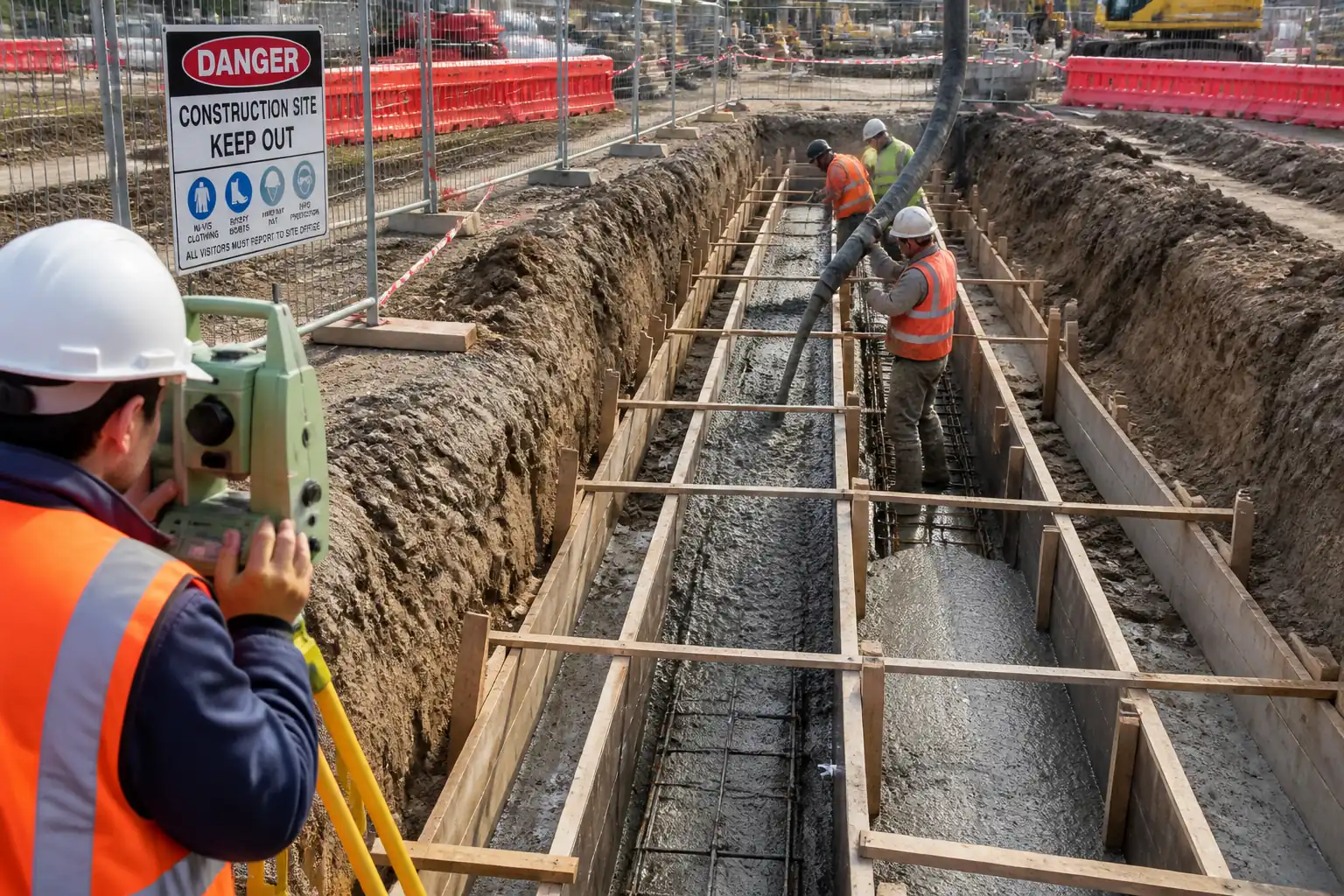
| 1 | Setting Out and Controls | Survey and mark pile locations and cut-off levels using total station/RTK. Install reference benchmarks away from piling operations. | Surveyor | Independent check of coordinates/levels |
| 2 | Piling Platform and Access | Verify platform thickness, compaction, and drainage; install rig mats where required; define exclusion zones and haul routes. | TWC / Site Manager | Platform certificate review and visual inspection |
| 3 | Pre-Drill Checks | Confirm utilities clearance; verify rig, pump, lines, and gauges serviceability; ensure data logger active and job file set. | Piling Supervisor | Pre-start inspection |
| 4 | Auger Alignment and Positioning | Align auger over pile center using mast indicators; verify verticality. | Rig Operator | Visual/plumb; sensor reading |
| 5 | Auger Penetration (Drilling) | Drill with continuous rotation. Control RPM and crowd to avoid excessive soil loosening. Typical drilling: 20–35 rpm; penetration 0.3–0.8 m/min depending on soil [Verify]. | Rig Operator | Monitor torque/crowd on logger |
| 6 | Encountering Obstructions | If refusal/obstruction encountered, stop; assess with Engineer. Options: pre-drill with coring, chisel, or relocate per design. | Piling Supervisor/Engineer | Stop-work and assess |
| 7 | Toe Confirmation | Confirm final depth via encoder and correlate to design toe level; allow additional 0.3–0.5 m penetration into bearing stratum if specified [Verify]. | Rig Operator / QA | Logger and depth check |
| 8 | Concrete Pump Priming and Readiness | Prime line with grout/cement slurry if specified; confirm continuous supply on standby truck. Verify pressure gauge zero and logger channels for pressure/flow active. | Pump Operator / QA | Line inspection |
| 9 | Initial Charging of Auger Toe | Start concrete pumping before auger extraction until pressure stabilizes. Ensure toe fully charged; avoid loss of head. | Rig & Pump Operators | Monitor pressure and flow |
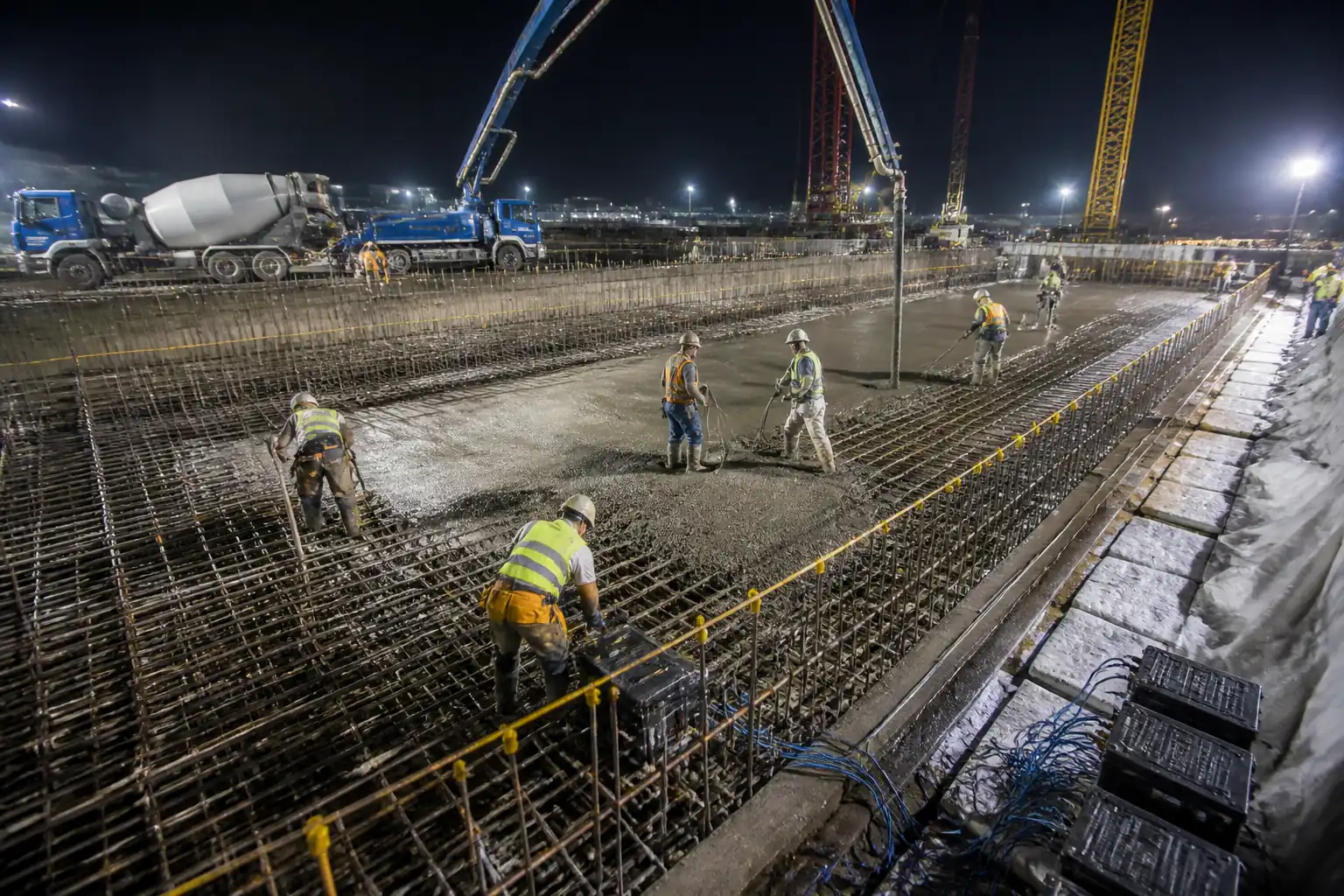
| 10 | Controlled Auger Extraction with Continuous Pumping | Extract auger steadily while pumping concrete through hollow stem. Adjust extraction speed to maintain positive concrete head above auger tip (≥1.5–2.0 m) and target volume factor 1.10–1.35 of theoretical (soil dependent). Typical extraction 0.3–0.7 m/min [Verify]. | Rig & Pump Operators | Real-time logger review by Supervisor/QA |
| 11 | Completion at Cut-off Level | Stop extraction when concrete reaches above design cut-off to allowance (typically +0.3 to +0.8 m) for trimming [Verify]. Remove auger fully, avoiding suction. | Rig Operator | Visual and logger check |
| 12 | Fresh Concrete Sampling and Testing | Sample at pump discharge during steady flow. Perform slump (EN 12350-2) or slump-flow (EN 12350-8), temperature, density (EN 12350-6). Prepare cubes/cylinders (EN 12390-2). | QA/QC Technician | Witness by Engineer (if hold) |
| 13 | Reinforcement Cage Installation with Vibration | Lift cage with certified crane; align and insert into fresh concrete using external vibrator/poker to assist penetration. Maintain cover using spacers/centralizers. Avoid excessive vibration causing segregation. | Piling Supervisor / Steel Fixers | Visual; measure embedment and projection |
| 14 | Pile Head Protection and Identification | Mark pile ID, date/time, and level. Install temporary protection around green concrete. Prevent contamination or traffic loads. | Site Manager | Site inspection |
| 15 | As-Built Survey | Survey pile centers at cut-off or at accessible point after curing; adjust to grid. | Surveyor | QA review |
| 16 | Integrity/Load Testing (If Specified) | Carry out PIT (ASTM D5882) after minimum curing period (typically ≥3 days) and/or static load test per EN ISO 22477-1. Select piles per testing plan. | Testing Subcontractor / QA | Witness by Engineer |
| 17 | Pile Head Trimming | After sufficient strength gain, break down to design cut-off; remove weak laitance/debris; protect reinforcement. | Site Team | QA/Engineer inspection |
| 18 | Records and Handover | Compile rig data logs, concrete tests, cage records, as-built, and inspection forms; submit for approval. | QA/QC Engineer | Document review |
Health, Safety and Environment – Safety Controls
Task-Specific Hazards and Controls
- Hazard: Underground service strike during auger penetration
- Consequence: Electrocution, flooding, gas release, major service outage
- Engineering/Procedural Control: Permit-to-dig; reviewed utility maps; GPR/locating; trial holes where uncertainty; restricted drill depth until cleared; spotter present.
- Required PPE: Dielectric gloves when required, safety boots, arc-rated clothing if working near HV, eye/face protection.
- Collective Preventive Measure: Physical barriers and exclusion zone; lock-out from utility owners if applicable.
-
Inspection/Permit/Supervision: Permit-to-dig signed; pre-start briefing; Supervisor sign-off. [Verify per project HSE plan and local regulations]
-
Hazard: Rig instability/overturn due to inadequate platform
- Consequence: Crushing, equipment damage, ground collapse
- Engineering/Procedural Control: TWC-designed platform with bearing capacity verified; outrigger mats; slope limits; daily platform inspection; stop work in excessive rainfall.
- Required PPE: Hard hat, high-visibility clothing, safety boots.
- Collective Preventive Measure: Exclusion zones around rig swing radius.
-
Inspection/Permit/Supervision: Platform certificate; daily checklist; Supervisor authorization.
-
Hazard: High-pressure concrete hose/line failure
- Consequence: Injection injury, impact, splatter burns/alkaline burns
- Engineering/Procedural Control: Pressure test and certification; whip checks; secure couplings; line routed to minimize bends; pressure relief protocol; never stand over couplings.
- Required PPE: Face shield, safety goggles, alkali-resistant gloves, long sleeves, waterproof over-trousers.
- Collective Preventive Measure: Pump exclusion zone; barricades; emergency stop accessible.
-
Inspection/Permit/Supervision: Hose inspection each shift; pressure gauge functional; permit-to-pump.
-
Hazard: Entanglement with rotating auger/rig components
- Consequence: Severe lacerations, amputation, fatality
- Engineering/Procedural Control: Interlocked guards; clear separation distance; banksman control; no manual handling near rotating parts; lock-out before maintenance.
- Required PPE: Tight-fitting clothing, gloves suitable for task, hard hat, eye protection.
- Collective Preventive Measure: Physical barriers, spotter, two-way radios.
-
Inspection/Permit/Supervision: Supervisor authorization; LOTOTO for maintenance.
-
Hazard: Lifting operations for reinforcement cages
- Consequence: Dropped loads/crushing
- Engineering/Procedural Control: Lift plan; certified crane and lifting gear; tag lines; no personnel under suspended load; weather/wind limits observed.
- Required PPE: Hard hat with chin strap, gloves, safety boots, high-vis.
- Collective Preventive Measure: Exclusion zone with banksman control.
-
Inspection/Permit/Supervision: LOLER/3rd-party certs; pre-lift check; appointed person sign-off.
-
Hazard: Vibratory insertion of cage
- Consequence: Hand-arm vibration, ejection/splash of concrete, pinching
- Engineering/Procedural Control: Use handles/remote triggers; limit exposure time; maintain grip and stance; low‑slump splash guards; control vibration amplitude.
- Required PPE: Anti-vibration gloves, face shield, waterproof clothing.
- Collective Preventive Measure: Barriers to protect bystanders; task rotation.
-
Inspection/Permit/Supervision: HAVS monitoring; Supervisor oversight.
-
Hazard: Cementitious burns and respiratory irritation
- Consequence: Chemical burns, dermatitis, eye injury
- Engineering/Procedural Control: Wash stations; neutralizing agents; no hand immersion; use tools for sampling; prompt decontamination.
- Required PPE: Chemical-resistant gloves, goggles/face shield, long sleeves.
- Collective Preventive Measure: Designated wash/welfare area.
-
Inspection/Permit/Supervision: HSE inspections; first-aid readiness.
-
Hazard: Overhead lines/proximity hazards
- Consequence: Electrocution, arcing
- Engineering/Procedural Control: Minimum approach distances; de-energization or physical barriers; spotter guidance; boom height limiters if available.
- Required PPE: As per utility requirements.
- Collective Preventive Measure: Exclusion/buffer zones marked on ground.
-
Inspection/Permit/Supervision: Permit to work near HV; coordination with utility owner.
-
Hazard: Noise and vibration
- Consequence: Hearing loss, nuisance to neighbors
- Engineering/Procedural Control: Maintain equipment; use acoustic shrouds where feasible; schedule within permitted hours.
- Required PPE: Hearing protection (SNR rating suited to measured dB).
- Collective Preventive Measure: Noise barriers near receptors.
-
Inspection/Permit/Supervision: Noise monitoring logs; compliance with permits.
-
Hazard: Night/low visibility operations
- Consequence: Struck-by incidents
- Engineering/Procedural Control: Task lighting to ≥50 lux general and ≥200 lux workface [Verify]; reflective PPE; clear communication.
- Required PPE: High-vis, head torch as needed.
- Collective Preventive Measure: Light towers positioned to avoid glare.
- Inspection/Permit/Supervision: Night-work permit; Supervisor presence.
Environmental Controls
- Spoil/Arisings Management: Stockpile on impermeable membrane; classify per waste regulations; cover to prevent runoff; dispose to licensed facility with transfer notes.
- Concrete Washout: Dedicated lined washout pit; no discharge to surface water; vacuum recovery where mobile washout is used.
- Water/Slurry Control: Prevent concrete-contaminated water from entering drains; use silt socks/sedimentation tanks; pH monitoring if discharge permitted [Verify local permits].
- Noise and Working Hours: Comply with local ordinances; use quieter plant modes; maintain mufflers; monitor dB at site boundary if required.
- Vibration to Sensitive Structures: Pre-condition surveys for adjacent assets; monitor PPV with trigger levels typically 5–10 mm/s at foundations [Verify].
- Air Quality and Dust: Damp down haul roads; cover trucks; minimize rehandling of arisings; engines off when idle.
- Fuel and Chemical Storage: Bunded areas with 110% capacity; spill kits at pumps; immediate cleanup; report per incident procedure.
- Ecology/Watercourse Protection: Exclusion buffers; emergency spill response; no refueling within 20 m of watercourses [Verify].
- Waste Segregation: Metals (rebar offcuts), timber, plastics segregated; records maintained for recycling rates.
- Cultural/Archaeological Finds: Stop work and notify Engineer if unexpected finds encountered.
Quality Assurance and Quality Control (QA/QC)
Key Controls and Tolerances
- Pile Position: At cut-off within ±75 mm (≤750 mm dia) or ±100 mm (>750 mm dia) unless specified otherwise [Verify].
- Verticality: ≤1:100 deviation.
- Toe Level: Achieve design depth within −0/+100 mm unless directed; over-drill only with approval [Verify].
- Concrete Continuity: Maintain positive pressure and head; actual volume vs theoretical target 1.10–1.35 dependent on soil; investigate if <1.05 or >1.50.
- Concrete Properties: Workability at point of placement within approved range; temperature 5–35°C; strength per design at 28 days (EN 206, EN 12390).
- Cage Placement: Embedment to required depth; cover typically 50–75 mm with spacers; top projection ≥1000 mm above cut-off [Verify].
Testing Frequencies
- Fresh Concrete: Workability/temperature/density for each pile start and thereafter at least 1 set per 50 m³ and minimum 1 set per shift [Verify].
- Strength: 1 set of 3 cubes/cylinders per 50 m³ (7 & 28 days) [Verify].
- Integrity: PIT on percentage of working piles (typ. 100% for critical, else 20–50%) [Verify].
- Load Tests: As per spec (e.g., 1–2% of piles or as directed) [Verify].
Records and Data
- Automated rig logs (depth, torque, RPM, crowd, extraction rate, pressure, flow, volume vs depth) for each pile.
- Concrete delivery tickets, sampling sheets, test reports.
- Cage insertion and reinforcement inspection records.
- As-built pile register (ID, coordinates, dia, depth, volumes, dates).
Non-Conformance and Corrective Measures
- Triggers: Volume outside bands; loss of pressure; visible necking; deviation beyond tolerances; test failures.
- Actions: Stop and notify Engineer; consider re-drill/replace adjacent pile, remedial grouting, or load re-distribution per Designer’s direction. Root cause analysis and preventive actions documented.
Hold/Witness
- Hold: Pre-start setup (platform, calibration), first pile, trial mix, integrity/load testing setups.
- Witness: Fresh concrete tests, cage insertion measurements, as-built survey points.
Attachments
- Approved drawings and pile schedule.
- Piling platform design and certificate.
- Equipment calibration certificates (logger, depth encoder, pressure, flow) and maintenance records.
- Concrete mix design approval, material datasheets (cement, admixtures), and ready-mix plant certification.
- Lifting plans, certificates of cranes and lifting accessories.
- Risk assessments and method statements (RAMS); permits to dig/pump/night work as applicable.
- Pre-pour checklists; cage inspection sheets.
- Daily rig data logs and exports (CSV/PDF) with pressure/flow/volume traces per pile.
- Concrete sampling records, test reports (fresh and hardened).
- Integrity/load testing plans and reports.
- As-built survey records and final pile register.
- Non-conformance reports and corrective action close-outs.
This content is a read-only public reference. Download or customize to get an editable version.
ITP preview
The first inspection activities from the linked ITP for Method Statement – Continuous Flight Auger (CFA) Piling Works:
| Activity | Inspection / Test | Acceptance Criteria | Responsibility | Record |
|---|---|---|---|---|
| Method Statement/ITP Approval | Document review/approval | Approved prior to works commencement | Contractor QA/QC / Client Rep | Approved MS/ITP, distribution sheet |
| Piling Platform Certification | Visual and certificate review | Platform certificate valid; platform intact and level within tolerance | TWC / QA/QC | Platform certificate; daily checklist |
| Set-out Verification | Coordinate/level check | Pile center within ±10 mm pre-drill; benchmarks protected | Surveyor / QA/QC | Set-out report |
Showing 3 of 15 inspection activities. View full ITP →
Related Inspection and Test Plan
An Inspection and Test Plan (ITP) is available for Method Statement – Continuous Flight Auger (CFA) Piling Works. The ITP defines the inspection activities, acceptance criteria, hold and witness points, responsible parties, and records required to verify the work described in this method statement.
View the Method Statement – Continuous Flight Auger (CFA) Piling Works ITP →Frequently asked questions
Continue with related Quollnet resources connected to this method statement.