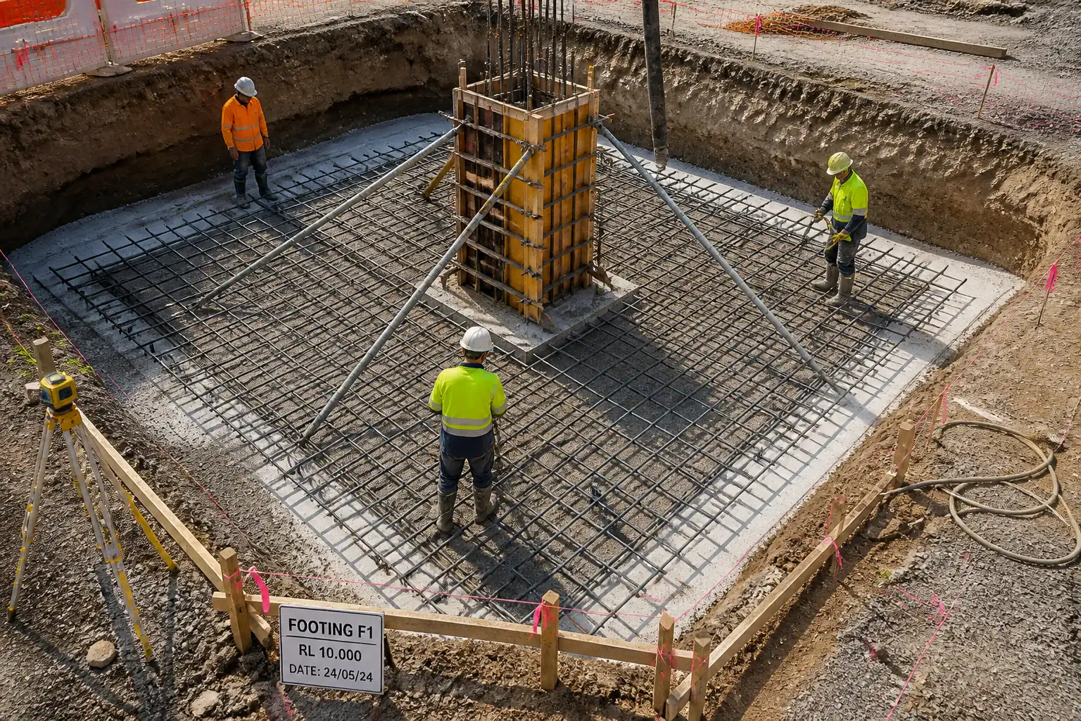
Inspection and Test Plan for Method Statement – Strip Footing Construction (Excavation to Waterproofing)
AI-assisted inspection and test plan connected to a method statement, with PDF and Excel export.
More than a static template
Unlike a downloadable Word or PDF template, this ITP is an AI-assisted editable starting point directly connected to its method statement. Every inspection activity, hold point, and acceptance criterion is structured and ready to adapt to your project.
- AI-assisted customization — Tailor inspection activities and acceptance criteria to your specific project scope.
- Linked method statement — This ITP is connected to the corresponding method statement describing the work sequence.
- Multiple export formats — Download as a formatted PDF or editable Excel spreadsheet.
- Editable starting point, not a final document — Review and verify all content against your project specifications and standards before use.
What you can customize
When you save this ITP to your account, every inspection row becomes editable. You can add, remove, or modify:
- Inspection activity — Description of what is being inspected.
- Inspection type — Hold point (H), Witness point (W), Review (R), or Monitor (M).
- Responsibility — Contractor, subcontractor, engineer, or client.
- Frequency — How often the inspection occurs.
- Acceptance criteria — Referenced standard or specification requirement.
- Records — Forms, test reports, or checklists required as evidence.
Why this ITP is used
To ensure all critical stages of strip footing construction are inspected and tested to meet design and specification requirements.
Who uses this inspection and test plan
Contractor QC, Site Engineers, Specialist Subcontractors, and the Engineer/Client’s Representative.
When this ITP is prepared and submitted
From pre-excavation through backfilling and handover, with defined Hold and Witness points before irreversible work proceeds.
Who receives or approves this ITP
Engineer/Client’s Representative for review and approval.
Inspection scope
Setting out, excavation formation, subgrade compaction, blinding, reinforcement, formwork, concrete placement and curing, joints, waterproofing, and backfill.
Typical hold, witness, and review points
Rebar inspection (Hold); pre-pour (Hold); waterproofing application (Hold); excavation formation (Witness); concrete placing (Witness).
Typical inspection records
ITRs, test results (FDT, slump, strengths), delivery tickets, rebar and formwork checklists, waterproofing QA tests, as-built survey, NCR/CAR.
Important approval note
This ITP is an AI-assisted editable starting point, not a pre-approved document. Before use on any project, all inspection activities, hold points, and acceptance criteria must be reviewed and approved by the relevant parties (superintendent, principal contractor, or client representative) in accordance with your contract and project quality plan.
Always verify acceptance criteria against your applicable drawings, specifications, and regulatory requirements. Hold points must be confirmed with the relevant authority before work proceeds past that point.
Inspection and test plan
| Activity | Inspection / Test | Acceptance Criteria | Responsibility | Record |
|---|---|---|---|---|
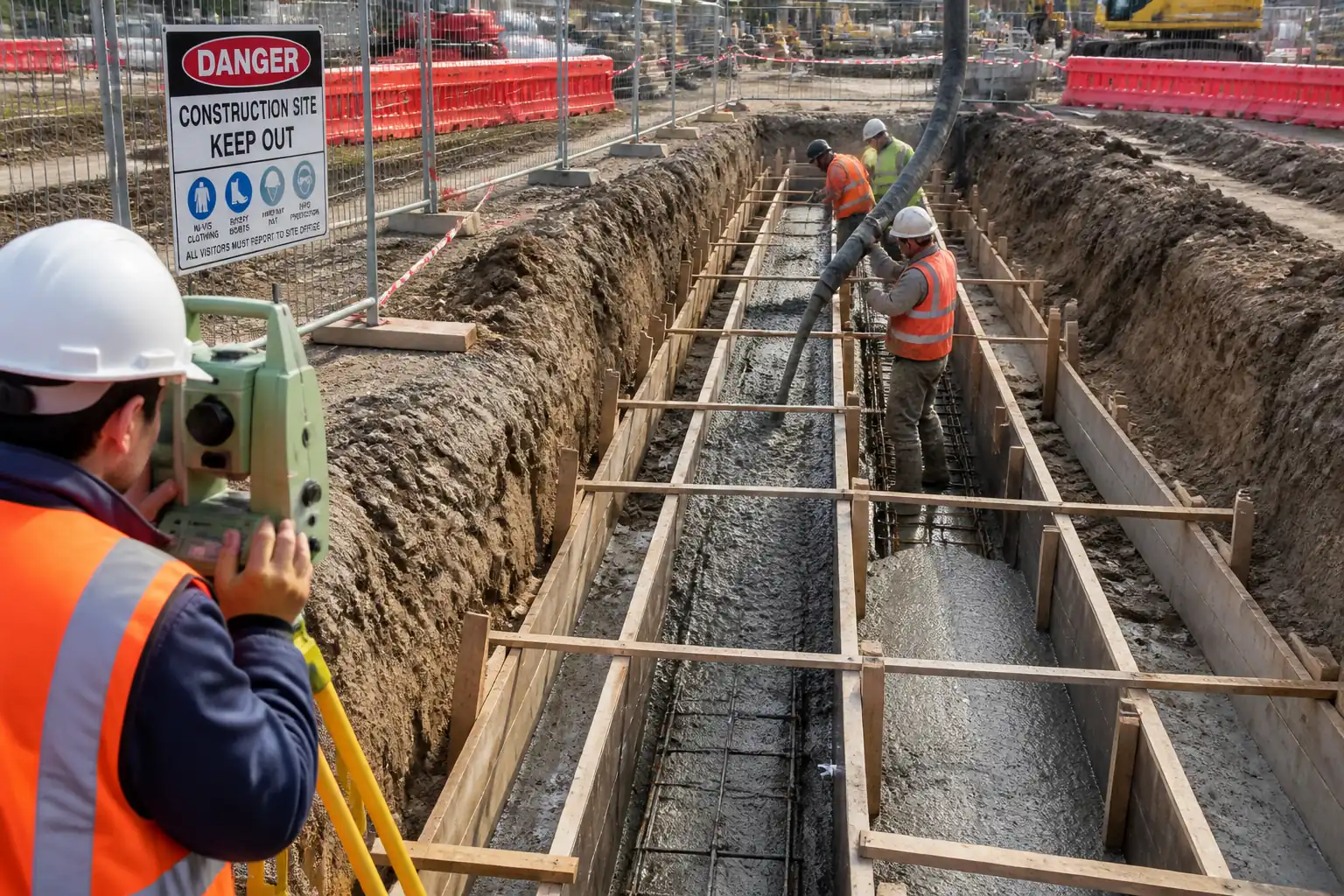
| Setting out and benchmarks | Line/level verification with total station | Control points established; line/level within ±5 mm; records completed. | Surveyor / QC / Engineer (Witness) | Survey report; ITR approved |
| Utility clearance | Scan results/trial pit verification | No-conflict confirmed or protection installed; Permit to Dig active. | Site Engineer / HSE / Engineer (Witness) | Utility clearance form; photos |
| Excavation to formation | Level survey; stability/groundwater check | Level +0/−50 mm; faces stable; dry or controlled water. | QC / Engineer (Witness) | Excavation ITR; survey sheet |
| Subgrade proof-rolling and compaction | FDT (nuclear/sand cone) | ≥95% MDD; firm, non-pumping. | QC / Third-party lab | FDT reports; ITR |
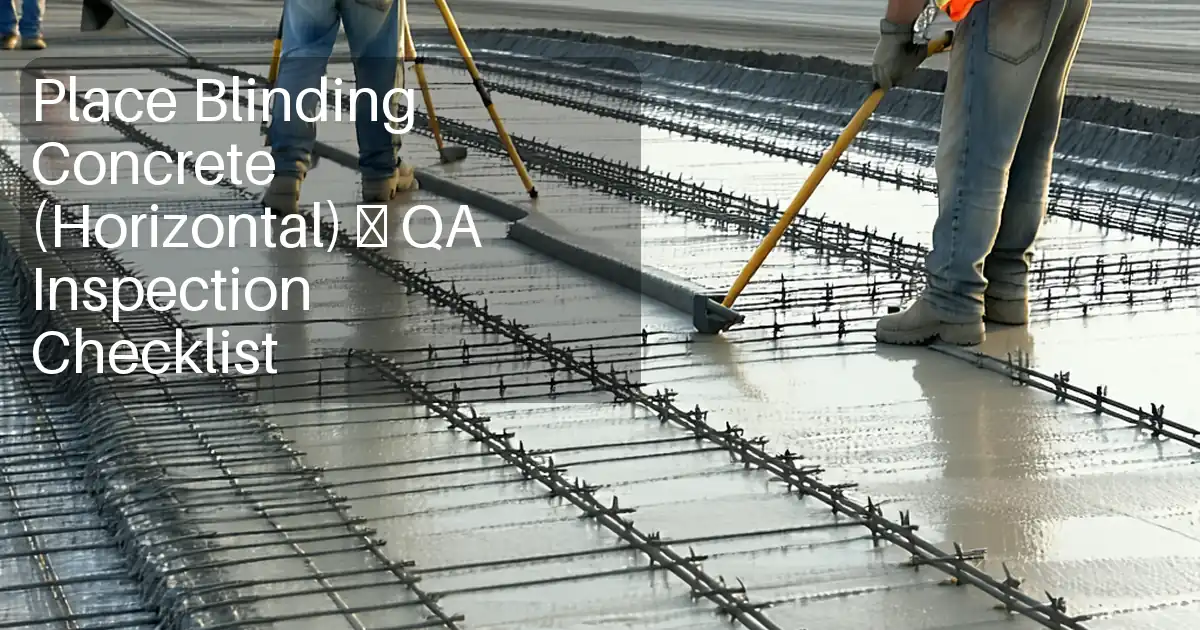
| Blinding concrete placement | Slump, temp; cubes if specified | Thickness 50–75 mm; level ±10 mm; curing commenced. | QC / Engineer (Witness) | Tickets; test results; ITR |
| Reinforcement inspection | Bar size/spacing/lap/cover check | As per drawings/BS 8666; cover 50–75 mm; clean and tied. | QC / Engineer (Hold) | Rebar ITR; checklist; photos |
| Formwork and dimensions | Dimensional/plumb check; release agent applied | Width/height ±10 mm; plumb ≤5 mm/1 m; grout-tight. | QC / Engineer (Witness) | Formwork ITR; checklist |
| Pre-pour inspection | Pre-pour checklist | All preceding NCRs closed; pour approval issued. | QC / Engineer (Hold) | Pre-pour ITR signed |
| Concrete delivery checks | Ticket verification; time; mix ID | Compliant with approved mix; within delivery time limits. | QC | Delivery tickets; log |
| Fresh concrete tests | Slump (EN 12350-2/ASTM C143); temp; air (if specified); sampling (EN 12350-1/ASTM C172) | Within specified slump/air/temperature ranges. | QC / Lab | Field test sheets; sample IDs |
| Concrete placing and vibration | Observation vs ACI 304; vibration practice | Layer ≤300–400 mm; no segregation; no rebar displacement. | QC (Witness) / Site Engineer | Pour log; photos |
| Curing and protection | Curing application and duration check | Curing continuous ≥7 days [Verify]; surfaces protected. | QC | Curing records |
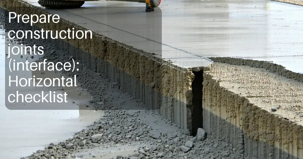
| Construction joint preparation (if applicable) | Surface roughness; cleanliness; bonding agent application | ≥5 mm amplitude roughness; sound substrate; accessories installed. | QC / Engineer (Hold) | Joint prep ITR; photos |
| Waterproofing application | Visual, spark/holiday test or adhesion (as specified) | Continuous membrane; correct laps/DFT; terminations sealed; protection boards installed. | QC / Engineer (Hold) | Waterproofing ITR; test reports; manufacturer warranty (if any) |
| Backfilling adjacent to footing | Layer thickness; FDT (as required) | 92–95% MDD [Verify]; no membrane damage; maintain drainage path. | QC | Backfill ITR; FDT reports |
| As-built survey and documentation | Survey check vs design | Levels/dimensions within tolerance; QA dossier complete. | Surveyor / QC / Engineer (Witness) | As-built drawings; QA handover pack |
This table is a read-only public reference. Download the PDF or Excel version, or customize this ITP to edit it for your project.
Frequently asked questions
Related method statement
This Inspection and Test Plan is associated with the Method Statement – Strip Footing Construction (Excavation to Waterproofing) method statement, which describes the step-by-step construction sequence, resources, materials, equipment, safety controls, and environmental controls for this activity.
View the Method Statement – Strip Footing Construction (Excavation to Waterproofing) method statement →Continue with related inspection, method statement, article, and checklist resources.