Method Statement – Strip Footing Construction (Excavation to Waterproofing) – Method Statement
AI-assisted method statement with matching ITP, PDF download, and Excel export.
More than a static template
Unlike a downloadable Word or PDF template, this method statement is an AI-assisted editable starting point connected directly to a matching Inspection and Test Plan. Every section is structured, project-adaptable, and ready to export.
- AI-assisted drafting — Customize every section with AI for your specific project scope.
- Linked ITP — A matching inspection and test plan is generated alongside the method statement.
- Multiple export formats — Download as a formatted PDF or editable Excel spreadsheet.
- Editable starting point, not a final document — Review, verify, and adjust all content against your project requirements before use.
Static template vs. Quollnet workflow
| Feature | Static template | Quollnet |
|---|---|---|
| Project-specific content | Manual fill-in required | AI-assisted customization |
| Linked ITP | Separate document, no link | Matching ITP included |
| Export formats | Usually PDF only | PDF and Excel |
| Structured sections | Free-form layout | 13 standardized sections |
| Saved to your account | Local file only | Cloud-saved, reusable |
| Content accuracy | You verify everything | AI-assisted, you still verify |
| Cost | Often free but time-intensive | Free to customize and download |
What you can customize
When you save this method statement to your account, every section becomes editable. The following 13 sections are included:
- Scope — Defines the activity and its boundaries.
- References — Standards, specifications, and drawings.
- Responsibilities — Roles and accountabilities.
- Resources — Labour, plant, and equipment summary.
- Materials — Materials and compliance requirements.
- Equipment — Tools and equipment details.
- Prerequisites — Hold points and pre-conditions.
- Method sequence — Step-by-step construction sequence.
- Safety controls — HSE risk controls and PPE.
- Environmental controls — Environmental mitigation measures.
- QA/QC — Quality inspection and test requirements.
- ITP — Inspection and Test Plan table (has its own page).
- Attachments — Referenced drawings and documentation.
Why this method statement is used
This method statement is used to define and communicate the approved procedure for carrying out method statement – strip footing construction (excavation to waterproofing) on site. It ensures the work is planned in advance, the correct resources and controls are in place, and all personnel understand responsibilities, sequence, quality requirements, and safety controls before work begins. It aligns site execution with the documented scope and acceptance expectations.
Who uses this method statement
This method statement is used by contractors, site supervisors, project engineers, QA/QC engineers, HSE officers, consultants, and client representatives. It serves as a shared reference for planning, execution, supervision, inspection, and approval of the activity on site.
When it is prepared and submitted
The method statement is prepared before the work activity starts and submitted as part of the pre-construction documentation package for review and approval.
Who reviews or approves it
The method statement is usually submitted to the client representative, consultant, resident engineer, or project management consultant for review and approval before the work commences.
Important approval note
This method statement is an AI-assisted editable starting point, not a pre-approved document. Before use on any project, all content must be reviewed and approved by the relevant parties (superintendent, principal contractor, or client representative) in accordance with your contract and project quality plan.
For example: if your specification requires a departure from a referenced standard, that departure must be documented and approved separately — this method statement will not capture that automatically. Always verify against your applicable drawings, specifications, and regulatory requirements.
Method statement content
Scope
Overview
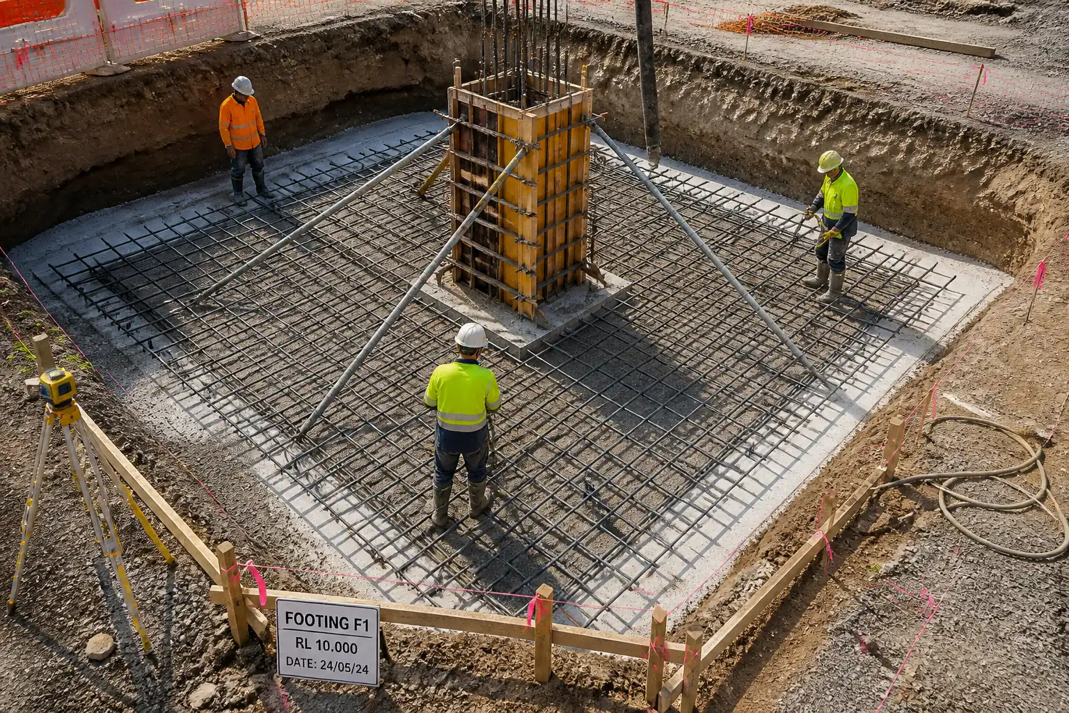
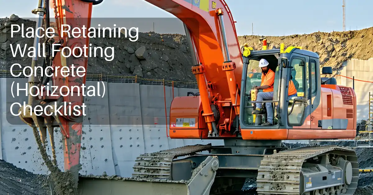
This method statement covers the complete execution of strip foundations for load-bearing masonry or concrete walls, from ground excavation through subgrade preparation, blinding, reinforcement, formwork, concrete placement, construction joint preparation, curing, waterproofing, and controlled backfilling. It includes quality control testing, inspection and record requirements, and task-specific HSE and environmental controls.
Included Activities
- Setting out and utility clearance.
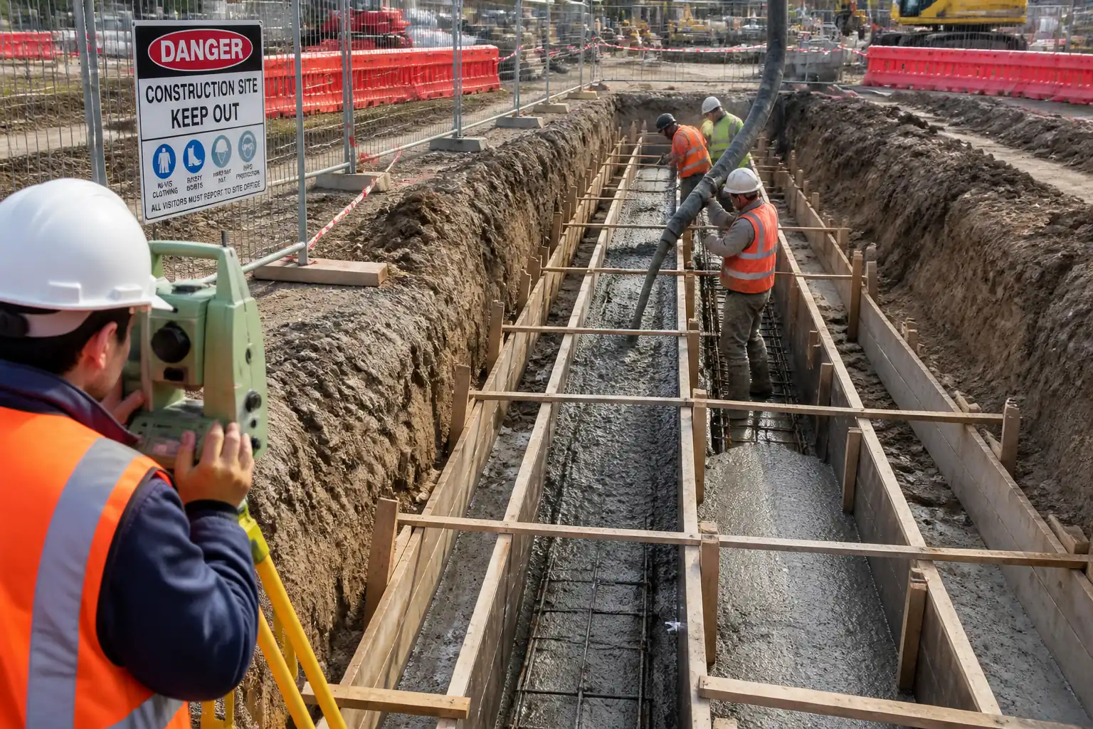
- Excavation to formation level with safe slopes or shoring, dewatering as needed.
- Subgrade trimming, proof-rolling, replacement of soft spots, and compaction.
- Lean concrete blinding layer (typically 50–75 mm thick) [Verify per project specifications].
- Reinforcement cutting, bending, cage fabrication and placement including cover control and starter bars.
- Formwork installation, alignment, and sealing to prevent grout loss.
- Concrete supply, acceptance, placing, consolidation, finishing, and curing.
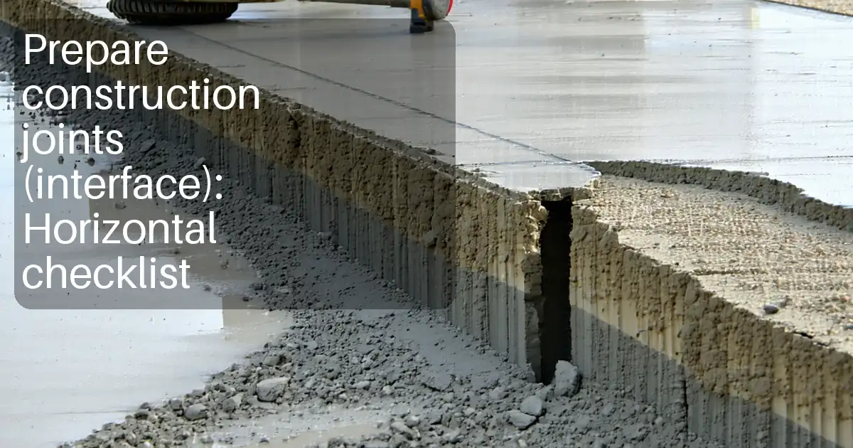
- Construction joint preparation where required.
- Application of foundation waterproofing (membrane or liquid-applied), protection board, and drainage composites where specified.
- As-built survey and closeout documentation.
Exclusions
- Pile foundations, raft foundations, deep basements outside strip footing scope, above-DPC wall construction unless specifically noted, temporary works design outside of excavation support unless stated.
Key Performance Targets [Verify per project specifications]
- Excavation level tolerance: +0 / −50 mm; blinding level: ±10 mm.
- Subgrade compaction: ≥95% MDD (ASTM D1557/EN equivalent) where replacement is executed.
- Concrete strength class (typical): C25/30 (or f’c ≈ 30 MPa) with target slump 75–150 mm if pumped/plasticized.
- Concrete cover to reinforcement: 50–75 mm to formed surfaces or cast against blinding depending on exposure.
- Waterproofing laps: torch-on 75–100 mm; liquid-applied minimum dry film thickness as per manufacturer.
References
| Document Type | Reference / Number | Revision | Notes |
|---|---|---|---|
| Standard | BS EN 13670 – Execution of Concrete Structures | Concrete execution tolerances and workmanship. | |
| Standard | BS EN 206 – Concrete. Specification, performance, production and conformity | Concrete specification and conformity. | |
| Standard | EN 1992-1-1 (Eurocode 2) / ACI 318 – Structural Concrete Design and Detailing | Design provisions, cover, laps per design. | |
| Standard | ACI 301 / ACI 304R – Concrete Specifications and Placing | Concrete placement, consolidation, and finishes. | |
| Standard | ACI 305R / ACI 306R – Hot and Cold Weather Concreting | Temperature control in placing and curing. | |
| Standard | ACI 347R – Guide to Formwork for Concrete | Formwork materials, pressures, stripping guidance. | |
| Standard | BS 8102 – Protection of Below Ground Structures Against Water Ingress | Waterproofing selection and performance grades. | |
| Standard | BS 4449 / BS 8666 or ASTM A615/A706 – Reinforcing Steel and Bending Schedules | Rebar material and detailing requirements. | |
| Standard | ASTM C94, C172, C143, C231, C138, C31/C39 / EN 12350 & EN 12390 series | Ready-mix delivery, sampling, slump, air, density, and strength tests. | |
| Standard | ASTM D1557, D6938, D1556 / BS 1377 / EN ISO 17892 | Compaction specification and field density testing. | |
| Guideline/Regulation | PAS 128 – Underground Utility Detection [or local equivalent] | Utility survey quality levels. | |
| Regulation | Local Excavation Safety Regulations / OSHA 29 CFR 1926 Subpart P [Verify per local law] | Excavation support, access/egress, and monitoring. |
Responsibilities
| Role | Responsibility | Name / Party |
|---|---|---|
| Project Manager | Overall delivery, resources, and coordination; approval of method and risk controls. | Contractor |
| Site Engineer | Setting out, levels, supervision of sequence, checks before pour. | Contractor |
| QA/QC Engineer | Hold/witness points, materials approval, coordination of tests, NCR/Corrective Actions. | Contractor |
| HSE Manager / Officer | Risk assessments, permits (excavation, hot work), TBTs, site inspections. | Contractor |
| Land Surveyor | Primary setting out, benchmarks, as-built surveys. | Contractor |
| General Foreman | Daily supervision of trades, productivity, housekeeping, permits compliance. | Contractor |
| Steel Fixing Supervisor | Cut, bend, fix reinforcement per drawings and standards; ensure cover blocks/spacers. | Contractor |
| Formwork Supervisor | Install and align formwork; ensure tight joints and release application. | Contractor |
| Concrete Plant / Supplier QA Rep | Concrete supply per approved mix, delivery tickets, truck compliance, admixture control. | Supplier |
| Waterproofing Supervisor | Apply waterproofing, QA tests (adhesion, holiday/spark test if specified). | Specialist Subcontractor |
| Engineer/Consultant’s Representative | Review and approve inspections, samples, test results; issue ITR approvals. | Engineer/Client |
Resources
| Resource Type | Description | Quantity | Remarks |
|---|---|---|---|
| Earthworks crew | 1 foreman, 1 operator, 2 laborers [Verify] | ||
| Steel fixers | 1 supervisor, 3–6 fixers [Verify] | ||
| Formwork team | 1 chargehand, 3 carpenters, 2 helpers [Verify] | ||
| Concrete crew | 1 pump operator, 2 finishers, 2 laborers [Verify] | ||
| Waterproofing crew | 1 supervisor, 2 applicators [Verify] | ||
| Survey team | 1 surveyor, 1 assistant [Verify] | ||
| HSE team | 1 HSE officer shared [Verify] |
Materials
| Material | Specification / Grade | Quantity | Remarks |
|---|---|---|---|
| Blinding concrete (e.g., C8/10 or 10 MPa) | BS EN 206; max aggregate per cover; 75–150 mm slump [Verify] | 50–75 mm thickness [Verify] | |
| Structural concrete (e.g., C25/30; f’c ≈ 30 MPa) | BS EN 206 / ASTM C94; w/c ≤ 0.55 [Verify]; target slump 75–150 mm if pumped | As per drawings | |
| Rebar (B500B/BS 4449 or ASTM A615 Gr 60) & tie wire | BS 8666 bending; laps per design (typ. 40–50d) [Verify] | As per BBS | |
| Cover blocks/spacers (50–75 mm) | Concrete spacers equal grade to structural concrete; side spacers plastic allowed [Verify] | As required | |
| Formwork timber/ply, release agent, joint sealant | ACI 347R; release agent compatible with waterproofing | As required | |
| Curing compound/water and hessian | ASTM C309 for compounds; curing ≥7 days [Verify] | As required | |
| Waterproofing (SBS torch-on 3–4 mm or liquid-applied) + primer | BS 8102; manufacturer’s system data sheet; Laps 75–100 mm; DFT per datasheet | As per drawings | |
| Protection boards, drainage composite, geotextile | Manufacturer system; EN standards for geosynthetics [Verify] | As per drawings | |
| Hydrophilic waterstops/sealants | Compatible with joint conditions; install per datasheet | As required |
Equipment
| Equipment | Capacity / Type | Quantity | Inspection Required |
|---|---|---|---|
| Tracked excavator | 15–22 t | Daily inspection + certification [Verify] | |
| Dump trucks | 10–20 m³ | Road-worthiness and tarpaulins | |
| Plate compactor / roller | 100 kg / 3–5 t | Pre-use checks | |
| Submersible pumps & hoses | 2–3 in | PAT/elec checks; standby pump | |
| Total station / laser level | Calibration certs | ||
| Rebar cutter/bender, tying tools | Guards and training | ||
| Truck mixers, concrete pump (if used) | Pressure test/line integrity [Verify] | ||
| Internal vibrators | 25–50 mm head | Spare unit on site | |
| Slump cone, thermometers, cube/cylinder molds | Calibrated equipment | ||
| Trench boxes/shoring, ladders, edge protection | Engineer-designed where required [Verify] | ||
| Torch sets/rollers (SBS) or sprayer (liquid) | Hot work permit + fire watch [Verify] |
Prerequisites
- Approved IFC drawings, reinforcement schedules (BBS), and waterproofing system datasheets.
- Approved method statement, risk assessment, and ITP including defined Hold/Witness points.
- Permit to Dig/Excavate; utility survey (PAS 128 or equivalent) and marked exclusion zones; trial pits where required.
- Temporary works design (shoring/benching) for excavation if stability is not ensured by safe slopes.
- Dewatering plan and discharge consent; standby pump and power.
- Approved concrete mix design, delivery and testing plan; laboratory approvals.
- Calibrations: survey equipment, slump cone, thermometers, weighing scales, vibrators checks.
- Inspection forms: pre-excavation checklist, pre-pour checklist, waterproofing checklist.
- Toolbox Talk for excavation, lifting, concrete burns, hot works (if torch-on), and working adjacent to open trenches.
- Access and traffic management plan; spoil disposal route and licensed tip details.
- Weather review: hot/cold weather concreting controls ready per ACI 305/306.
- Materials on hand: spacers/cover blocks, formwork consumables, curing materials, waterproofing, protection boards, drainage composites.
- Lighting for early/late works and emergency/first aid provisions.
- Stakeholder notifications if vibration/noise limits apply.
Method Sequence
| Step | Activity | Description | Responsibility | Inspection / Hold Point |
|---|---|---|---|---|
| 1 | Pre-start briefing and permits | Conduct TBT; verify RAMS and ITP approvals; issue Permit to Dig and, if applicable, Hot Work and Lifting permits. | Site Engineer / HSE | HSE checks |
| 2 | Setting out | Establish control points; set footing centerlines and levels using total station/laser; install batter boards/string lines. | Surveyor | QC/Engineer verification |
| 3 | Utility clearance | Scan/services check; dig trial holes by hand/vacuum if in conflict areas; mark and protect services. | Site Engineer / HSE | HSE/Engineer |
| 4 | Excavation to formation | Excavate to formation allowing for blinding thickness; maintain safe slopes or install shoring; manage groundwater with pumps; stockpile or cart away spoil to approved tip. | Foreman / Operator | QC/Engineer check of level and stability |
| 5 | Subgrade preparation | Trim final 50 mm by manual means to avoid disturbance; proof-roll; identify soft spots; undercut and replace with compacted granular material; compact in ≤150–200 mm layers. | Foreman / QC | QC/Engineer |
| 6 | Blinding concrete | Place lean concrete (50–75 mm) to provide clean working surface and cover control; finish level/smooth. | Concrete Crew / QC | QC/Engineer pre-pour/post-pour |
| 7 | Rebar fabrication and placement | Cut/bend per BBS; assemble linear cages; fix spacers/cover blocks; place continuity bars/starters per wall detail; secure to prevent float/move. | Steel Fixing Supervisor | QC/Engineer rebar inspection |
| 8 | Formwork installation | Install side forms; plumb and align; seal joints; apply compatible release agent. | Formwork Supervisor | QC |
| 9 | Embedments and sleeves | Install hold-down bolts/starters/templates; verify projection and position. | Site Engineer | QC/Engineer |
| 10 | Pre-pour inspection | Clean forms/rebar; remove standing water; re-check levels/lines; confirm concrete delivery plan and test regime; confirm dewatering running. | QC / Engineer | Engineer witness |
| 11 | Concrete delivery acceptance | Verify ticket (mix ID, time, water added); perform slump and temperature; take specimens per frequency plan. | QC | QC |
| 12 | Concrete placing and vibration | Place in layers ≤300–400 mm; internal vibration with 25–50 mm heads; insertion spacing 8–10× head diameter; avoid contact with rebar/forms; prevent segregation. | Concrete Crew | QC |
| 13 | Finishing and curing | Strike off to level; commence curing within 30 minutes via wet cover or curing compound; protect from traffic/vibration. | Concrete Crew / QC | QC |
| 14 | Construction joint preparation (if pour interrupted) | Cut/locate joint at approved position; after set, roughen to 5 mm amplitude; remove laitance; clean; apply bonding agent or cement slurry; install hydrophilic strip/waterstop if specified. | Site Engineer / QC | QC/Engineer |
| 15 | Formwork striking and surface repairs | Remove side forms when concrete has sufficient strength (≥10 MPa or per calc) [Verify]; repair minor defects with approved mortar. | Formwork Supervisor / QC | QC |
| 16 | Waterproofing substrate prep | Ensure concrete cured/dry as per system; edges chamfered/filleted; surface clean and dry; apply primer. | Waterproofing Subcontractor | QC |
| 17 | Membrane application and protection | Apply torch-on or liquid membrane per manufacturer; ensure laps 75–100 mm (torch-on) and DFT for liquid; install protection/drainage boards and geotextile as specified. | Waterproofing Subcontractor | QC/Engineer |
| 18 | Backfilling adjacent to footing | Place selected fill in layers ≤200–300 mm; compact with light plant near wall; protect membrane with boards; maintain drainage layer. | Foreman / QC | QC |
| 19 | As-built survey and handover | Survey top of footing and key dims; compile QA dossier including test results and approvals; demobilize. | Surveyor / QA | Engineer |
HSE – Task-Specific Safety Controls
For each significant hazard, the following are defined: hazard, likely consequence, engineering/procedural control, required PPE, collective preventive measure, and inspection/permit/supervision requirement.
1) Underground utility strike
- Consequence: Electrocution, flooding, explosion, service outage.
- Control: PAS 128 survey, utility drawings review, CAT & Genny scan, hand-dig/vacuum around suspected services; establish exclusion zones.
- PPE: Dielectric gloves (if applicable), safety boots, eye protection, arc-rated PPE where required.
- Collective: Physical barriers and signage; lock-out/coordination with utility owners.
- Inspection/Permits: Permit to Dig; HSE supervision; records of scan. [Verify per project HSE plan and local regulations]
2) Trench/excavation collapse
- Consequence: Crushing/asphyxiation; serious injury/fatality.
- Control: Design shoring/benching per soil type; safe slopes; daily inspection by Competent Person; keep surcharge loads (>0.6 m from edge) and plant set-back.
- PPE: Hard hats, high-visibility vests, boots.
- Collective: Trench boxes/shoring; ladder access every ≤7.5 m; edge protection.
- Inspection/Permits: Excavation inspection log each shift; rainfall/water ingress monitoring; rescue plan.
3) Plant–person interface
- Consequence: Struck-by or crush injuries.
- Control: Segregated routes, banksman for reversing, exclusion zones during lifting/pouring; 360° cameras/alarms.
- PPE: Hi-vis, gloves, boots, hearing protection as required.
- Collective: Barriers, spotters, traffic management plan.
- Inspection/Permits: Daily plant checks; operator certification.
4) Lifting reinforcement cages/embeds
- Consequence: Dropped load injuries.
- Control: Certified lifting accessories; pre-use inspection; rated lifting points; lift plan; weather limits.
- PPE: Helmets with chin straps, gloves, boots.
- Collective: Exclusion zone; tag lines.
- Inspection/Permits: Appointed Person approval; lifting permit.
5) Rebar impalement and cuts
- Consequence: Puncture wounds, lacerations.
- Control: Rebar caps, bend over projections where feasible; keep work areas tidy; use tying tools.
- PPE: Cut-resistant gloves, long sleeves, eye protection.
- Collective: Edge protection and capping.
- Inspection/Permits: Supervisor checks; HSE inspections.
6) Concrete chemical burns and silica exposure
- Consequence: Dermatitis, alkali burns; respiratory irritation.
- Control: Wet concrete handling training; wash stations; avoid skin contact; control dust during trimming/sawing.
- PPE: Alkali-resistant gloves, long sleeves, eye/face protection; FFP2/FFP3 mask when cutting/grinding.
- Collective: Wet cutting with dust suppression; designated washout station.
- Inspection/Permits: COSHH/chemical register; SDS available.
7) Vibration/noise (vibrators, compactors)
- Consequence: HAVS, hearing loss.
- Control: Tool selection/maintenance; job rotation; exposure monitoring.
- PPE: Anti-vibration gloves (limited benefit), hearing protection (SNR per site noise levels).
- Collective: Administrative exposure limits; noise barriers if needed.
- Inspection/Permits: PAT testing; equipment log.
8) Hot works for torch-on membrane
- Consequence: Burns, fire.
- Control: Hot Work Permit; fire extinguishers; non-combustible substrates; remove combustibles; continuous fire watch and 60-min post-watch.
- PPE: Flame-resistant clothing, gloves, eye protection.
- Collective: Fire blankets, shields.
- Inspection/Permits: Hot Work Permit; trained operatives; calibrated gas equipment.
9) Water ingress and electrical hazards (pumps)
- Consequence: Drowning risk, electrocution.
- Control: RCD protection; cable management above water; standby pump; secure discharge away from edge.
- PPE: Rubber boots, gloves.
- Collective: Barriers; GFCI/RCD.
- Inspection/Permits: Electrical inspection tag; dewatering plan.
10) Slips, trips, and falls around excavations
- Consequence: Sprains, fractures.
- Control: Good housekeeping, non-slip walkways, adequate lighting; avoid stepping on rebar.
- PPE: Safety boots, headlamps if low light.
- Collective: Edge protection and walkways.
- Inspection/Permits: Supervisor walkdowns.
11) Manual handling of formwork/rebar
- Consequence: Musculoskeletal injuries.
- Control: Team lifts, mechanical aids, weight markings, training.
- PPE: Gloves, belts as appropriate.
- Collective: Use cranes/hoists for heavy items.
- Inspection/Permits: Manual handling assessment.
All controls must be verified per project HSE plan and local regulations.
Environmental Controls
- Dewatering and silt control: Route pump discharge through sediment bags or settlement tanks; obtain discharge consent; prevent erosion at outfalls.
- Concrete washout: Provide lined, bunded washout pit; no discharge to ground or drains; remove hardened waste to licensed facility.
- Dust suppression: Water spray on dry soils; cover stockpiles; wheel washing for trucks leaving site.
- Noise/vibration: Comply with local allowable hours; use well-maintained equipment and mufflers; monitor where sensitive receptors exist; pre-condition survey for adjacent structures if necessary.
- Waste management: Segregate timber, steel off-cuts, packaging; maintain waste transfer notes; recycle where possible.
- Spill prevention: Fuel/chemicals in double-bunded storage; spill kits at pumps and torching areas; trained responders.
- Protection of watercourses/drains: Cover or silt sock all nearby gullies; no primer/bitumen spills; store primers per SDS in ventilated area.
- Material stewardship: Use low-VOC primers where available; avoid over-ordering concrete; return unused admixtures to supplier.
- Ecology and trees: Respect root protection zones; no excavation or storage within protected areas without approval.
Quality Assurance & Quality Control
General
- Works executed per approved drawings, specifications, and referenced standards (BS EN 13670, BS EN 206/EN 12350/12390 or ASTM equivalents, ACI 301/304).
- ITP with defined Hold/Witness points governs inspections.
Testing and Inspection Frequencies [Verify per project specifications]
- Field density tests (FDT): 1 per 25 m run of footing or 1 per 200 m² of subgrade/replacement layer, whichever is greater.
- Blinding concrete: Slump each truck; strength testing if required by spec (min 1 set/day when used structurally).
- Structural concrete: At least 1 sample set (e.g., 6 cubes or cylinders) per 50 m³ per day; slump per truck; temperature each truck; air content if specified.
- Reinforcement: 100% visual inspection of size, spacing, laps, cover; check BBS compliance.
- Waterproofing: Visual continuity; spark/holiday test or adhesion test where specified; repair defects and retest.
Acceptance Criteria (typical)
- Excavation/formations: Levels +0/−50 mm; firm, non-pumping.
- Compaction: ≥95% MDD (ASTM D1557/EN ISO 17892) for replacement layers.
- Concrete: Strength ≥ specified f’c on 28-day average; slump within approved range; temp at discharge 5–35°C unless otherwise specified; placement within time limits (ASTM C94/EN 206).
- Reinforcement cover: 50–75 mm depending on exposure and blinding presence.
- Finish/tolerances: Dimensions within ±10 mm; surface free of honeycombing; deviations per BS EN 13670.
Documentation
- Inspection Test Requests (ITRs), test reports, delivery tickets, calibration certificates, material approvals, waterproofing warranties, as-built survey, NCR/CAR if deviations.
Nonconformance and Corrective Action
- Record NCRs for any deviation; agree corrective method with Engineer; retest/reinspect; update as-built records.
Attachments
- Approved IFC drawings and details for strip footings and waterproofing.
- Reinforcement bar bending schedules (BBS).
- Concrete mix design approvals and supplier certifications.
- Manufacturer datasheets and method statements for waterproofing system, primers, protection boards.
- ITP with Hold/Witness points; checklists (pre-excavation, rebar, formwork, pre-pour, waterproofing).
- Calibration certificates (survey equipment, testing apparatus, vibrators).
- Excavation support (temporary works) design, if applicable.
- Dewatering plan and discharge consent/permits.
- HSE documents: Risk Assessment, COSHH/SDS, TBT records, Permits (Dig, Hot Work, Lift), emergency plan.
- Waste management plan and disposal permits/tickets.
- As-built survey records and QA dossier index.
This content is a read-only public reference. Download or customize to get an editable version.
ITP preview
The first inspection activities from the linked ITP for Method Statement – Strip Footing Construction (Excavation to Waterproofing):
| Activity | Inspection / Test | Acceptance Criteria | Responsibility | Record |
|---|---|---|---|---|
| Setting out and benchmarks | Line/level verification with total station | Control points established; line/level within ±5 mm; records completed. | Surveyor / QC / Engineer (Witness) | Survey report; ITR approved |
| Utility clearance | Scan results/trial pit verification | No-conflict confirmed or protection installed; Permit to Dig active. | Site Engineer / HSE / Engineer (Witness) | Utility clearance form; photos |
| Excavation to formation | Level survey; stability/groundwater check | Level +0/−50 mm; faces stable; dry or controlled water. | QC / Engineer (Witness) | Excavation ITR; survey sheet |
Showing 3 of 16 inspection activities. View full ITP →
Related Inspection and Test Plan
An Inspection and Test Plan (ITP) is available for Method Statement – Strip Footing Construction (Excavation to Waterproofing). The ITP defines the inspection activities, acceptance criteria, hold and witness points, responsible parties, and records required to verify the work described in this method statement.
View the Method Statement – Strip Footing Construction (Excavation to Waterproofing) ITP →Frequently asked questions
Continue with related Quollnet resources connected to this method statement.