CFA Piling Method Statement — Auger Drilling, Continuous Concrete Placement & Cage Installation – Method Statement
AI-assisted method statement with matching ITP, PDF download, and Excel export.
More than a static template
Unlike a downloadable Word or PDF template, this method statement is an AI-assisted editable starting point connected directly to a matching Inspection and Test Plan. Every section is structured, project-adaptable, and ready to export.
- AI-assisted drafting — Customize every section with AI for your specific project scope.
- Linked ITP — A matching inspection and test plan is generated alongside the method statement.
- Multiple export formats — Download as a formatted PDF or editable Excel spreadsheet.
- Editable starting point, not a final document — Review, verify, and adjust all content against your project requirements before use.
Static template vs. Quollnet workflow
| Feature | Static template | Quollnet |
|---|---|---|
| Project-specific content | Manual fill-in required | AI-assisted customization |
| Linked ITP | Separate document, no link | Matching ITP included |
| Export formats | Usually PDF only | PDF and Excel |
| Structured sections | Free-form layout | 13 standardized sections |
| Saved to your account | Local file only | Cloud-saved, reusable |
| Content accuracy | You verify everything | AI-assisted, you still verify |
| Cost | Often free but time-intensive | Free to customize and download |
What you can customize
When you save this method statement to your account, every section becomes editable. The following 13 sections are included:
- Scope — Defines the activity and its boundaries.
- References — Standards, specifications, and drawings.
- Responsibilities — Roles and accountabilities.
- Resources — Labour, plant, and equipment summary.
- Materials — Materials and compliance requirements.
- Equipment — Tools and equipment details.
- Prerequisites — Hold points and pre-conditions.
- Method sequence — Step-by-step construction sequence.
- Safety controls — HSE risk controls and PPE.
- Environmental controls — Environmental mitigation measures.
- QA/QC — Quality inspection and test requirements.
- ITP — Inspection and Test Plan table (has its own page).
- Attachments — Referenced drawings and documentation.
Why this method statement is used
This method statement is used to define and communicate the approved procedure for carrying out cfa piling method statement — auger drilling, continuous concrete placement & cage installation on site. It ensures the work is planned in advance, the correct resources and controls are in place, and all personnel understand responsibilities, sequence, quality requirements, and safety controls before work begins. It aligns site execution with the documented scope and acceptance expectations.
Who uses this method statement
This method statement is used by contractors, site supervisors, project engineers, QA/QC engineers, HSE officers, consultants, and client representatives. It serves as a shared reference for planning, execution, supervision, inspection, and approval of the activity on site.
When it is prepared and submitted
The method statement is prepared before the work activity starts and submitted as part of the pre-construction documentation package for review and approval.
Who reviews or approves it
The method statement is usually submitted to the client representative, consultant, resident engineer, or project management consultant for review and approval before the work commences.
Important approval note
This method statement is an AI-assisted editable starting point, not a pre-approved document. Before use on any project, all content must be reviewed and approved by the relevant parties (superintendent, principal contractor, or client representative) in accordance with your contract and project quality plan.
For example: if your specification requires a departure from a referenced standard, that departure must be documented and approved separately — this method statement will not capture that automatically. Always verify against your applicable drawings, specifications, and regulatory requirements.
Method statement content
Scope
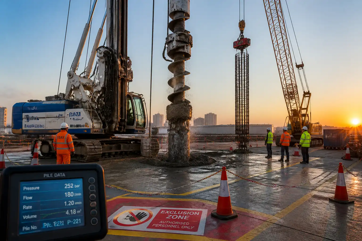
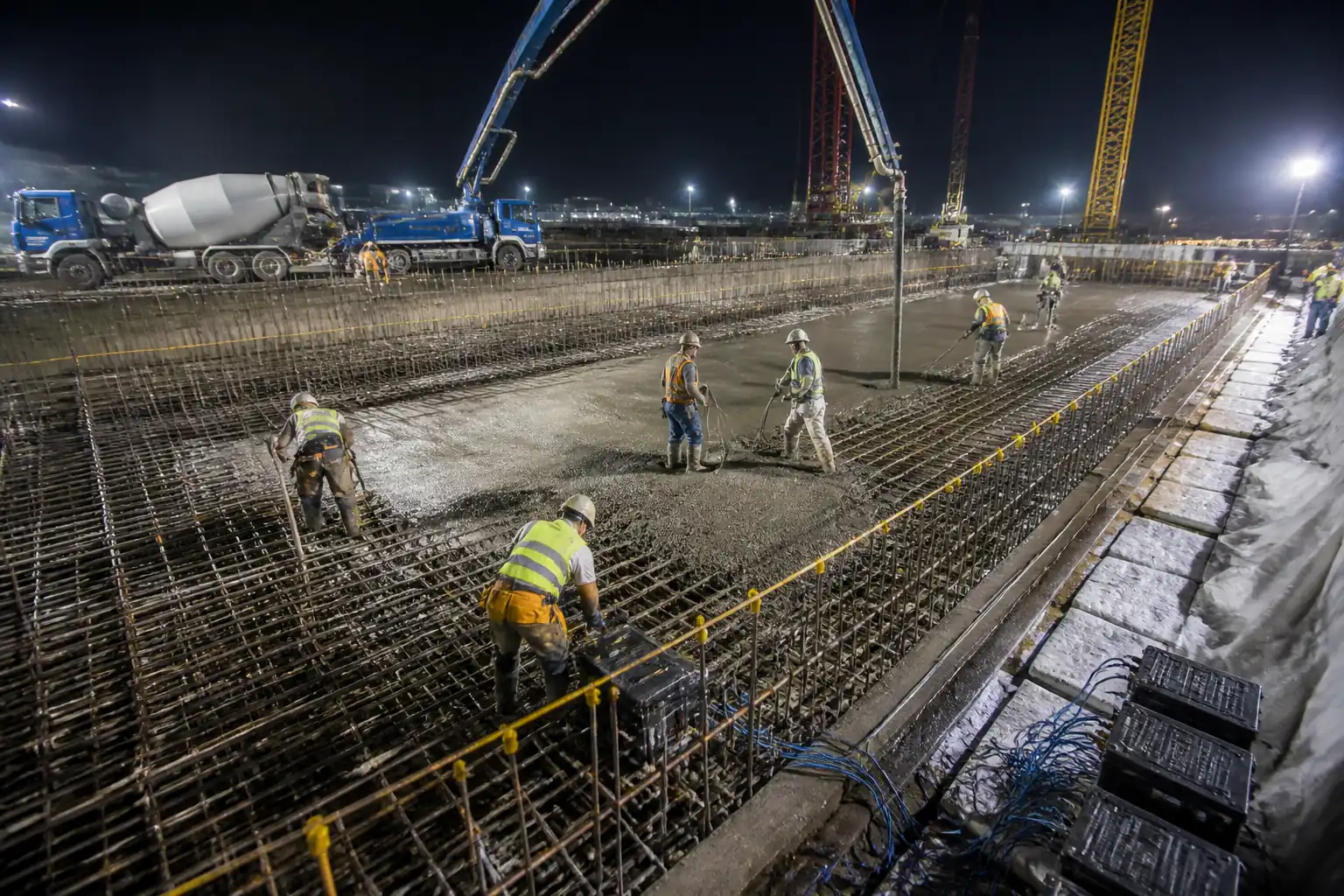
This method statement covers the execution, quality control and safety measures for Continuous Flight Auger (CFA) piling operations on . Works include mobilization, site set-out, auger drilling to design levels, continuous concrete pumping during auger extraction via hollow stem, automated geotechnical/plant monitoring and logging, reinforcement cage handling and insertion using vibratory equipment, pile positional and verticality control, fresh concrete sampling and acceptance testing, pile head formation, cut-off and final recording. Exclusions: driven piles, diaphragm walls and specialist grouting not defined here.
References
| Document Type | Reference / Number | Revision | Notes |
|---|---|---|---|
| Drawings & Specifications | Project Issued for Construction (IFC) drawings | Coordinate with Engineer | |
| Standards | BS EN 1997-1 (Eurocode 7), BS EN 206 (Concrete), BS 8004 (Foundations), PCA/CIRIA CFA guidance, Contractor Specification | ||
| Legislation | Health & Safety at Work Act 1974, CDM Regulations 2015, LOLER, PUWER, COSHH | ||
| Technical | CFA rig, pump and monitoring system manuals |
Responsibilities
| Role | Responsibility | Name / Party |
|---|---|---|
| Management | Ensure resources, schedules and approvals | Contractor |
| Supervision | Approve method, manage interfaces, issue instructions | Contractor |
| On-site control | Monitor drilling parameters, accept/reject piles on site | Contractor |
| Operative | Operate rig to specified rotation, torque and extraction rates | Contractor |
| Inspection | Carry out slump, temperature, produce cubes and verify automated logs | Contractor/Third-party Laboratory |
| Measurement | Establish pile grid, monitor positional tolerances and verticality | Contractor/Consultant |
Resources
| Resource Type | Description | Quantity | Remarks |
|---|---|---|---|
| Personnel | Piling supervisor, machine operator, banksman, labourers | As required | |
| Instrumentation | Automated drilling & concrete pressure logger, torque sensor, flow meter, data acquisition | 1 set | |
| Testing | Slump cone, temperature probe, curing tank and cube moulds, compressive testing machine (lab) | As required |
Materials
| Material | Specification / Grade | Quantity | Remarks |
|---|---|---|---|
| Concrete | As per project mix (e.g., C32/40 or specified) | Per pile volume | |
| Rebar | As per design (grade & diameter) | Per pile | |
Equipment
| Equipment | Capacity / Type | Quantity | Inspection Required |
|---|---|---|---|
| Hollow stem auger rig | Per project requirement | 1 | Yes |
| Concrete pump with pressure sensors | As required | 1 | Yes |
| Vibratory poker | 1 | Yes | |
| Total station / GNSS | 1 set | Yes |
Prerequisites and Preparatory Works
- Acceptance of design, drawings and pile schedule by Contractor and Engineer. 2. Site set-out and verification of pile positions by surveyor; utilities check and any protective measures in place. 3. Geotechnical report reviewed and site conditions verified. 4. RAMS (Risk Assessments & Method Statements) and permits to work issued and understood by all personnel. 5. Plant and equipment on-site, tested, inspected and with current calibration certificates. 6. Concrete mix design approved by Engineer and concrete supply arranged with batch tickets and testing plan. 7. Personnel competence checks completed (CPCS/NVQ or equivalent for plant operators, trained piling supervisor). 8. Environmental controls and washout management in place. 9. Access, lifting plans and traffic management implemented. 10. ITP and hold points communicated and witness/inspection arrangements agreed with Client/Engineer.
Method Sequence and Key Parameters
| Step | Activity | Description | Responsibility | Inspection / Hold Point |
|---|---|---|---|---|
| 1 | Mobilisation & set-out | Establish piling positions using grid coordinates; install welfare and exclusion zones | Surveyor / Site Manager | Survey set-out verification |
| 2 | Plant inspection & calibration | Pre-start checks, test runs and calibration of torque sensor, pressure transducer, flow meter and data logger | Plant Engineer / QA | Calibration certificates checked |
| 3 | Drilling to design depth (CFA drilling) | Advance hollow stem auger to design tip elevation using controlled rotation and feed. Typical parameters: rotation speed 15–60 rpm (site-dependent), penetration/advance rate 0.3–2.0 m/min depending on ground, monitor torque and penetration rate. Limit torque set per rig/manufacturer; stop and investigate if torque rises sharply or rotation stalls. | Driller / Piling Supervisor | Continuous monitoring of torque, rotation & penetration |
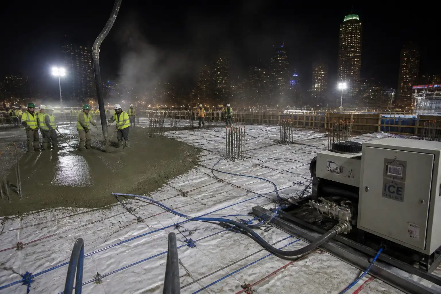
| 4 | Continuous concrete placement during auger extraction | Begin concrete pumping prior to starting auger extraction so concrete head is maintained in the hollow stem. Maintain steady pump flow matching extraction rate to avoid voids. Typical extraction rate 0.5–2.0 m/min; typical pump pressure monitoring band: maintain between 4–12 bar (site/manufacturer dependent). Never exceed pump or auger manufacturer pressure limits. Maintain positive concrete head to prevent soil ingress and ensure continuity. | Pump operator / Piling Supervisor | Continuous pressure and flow monitoring, match to depth/time logs |
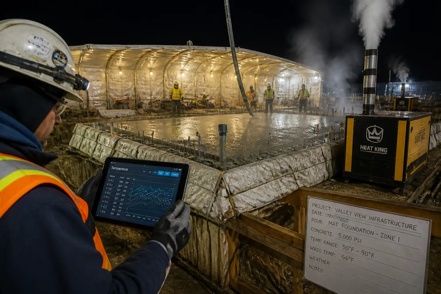
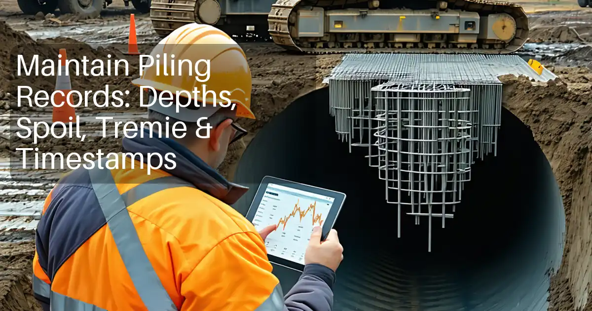
| 5 | Automated monitoring and logging | Record and store continuous data: time, depth, rotation speed (rpm), torque, penetration rate, concrete pressure, pump flow rate, concrete volume, GPS coordinates and ambient/ concrete temperature. Frequency: at least once per 5 seconds (preferable 1 Hz) captured to secure storage and backup. | QA / Operator | Real-time monitoring and post-pour review |
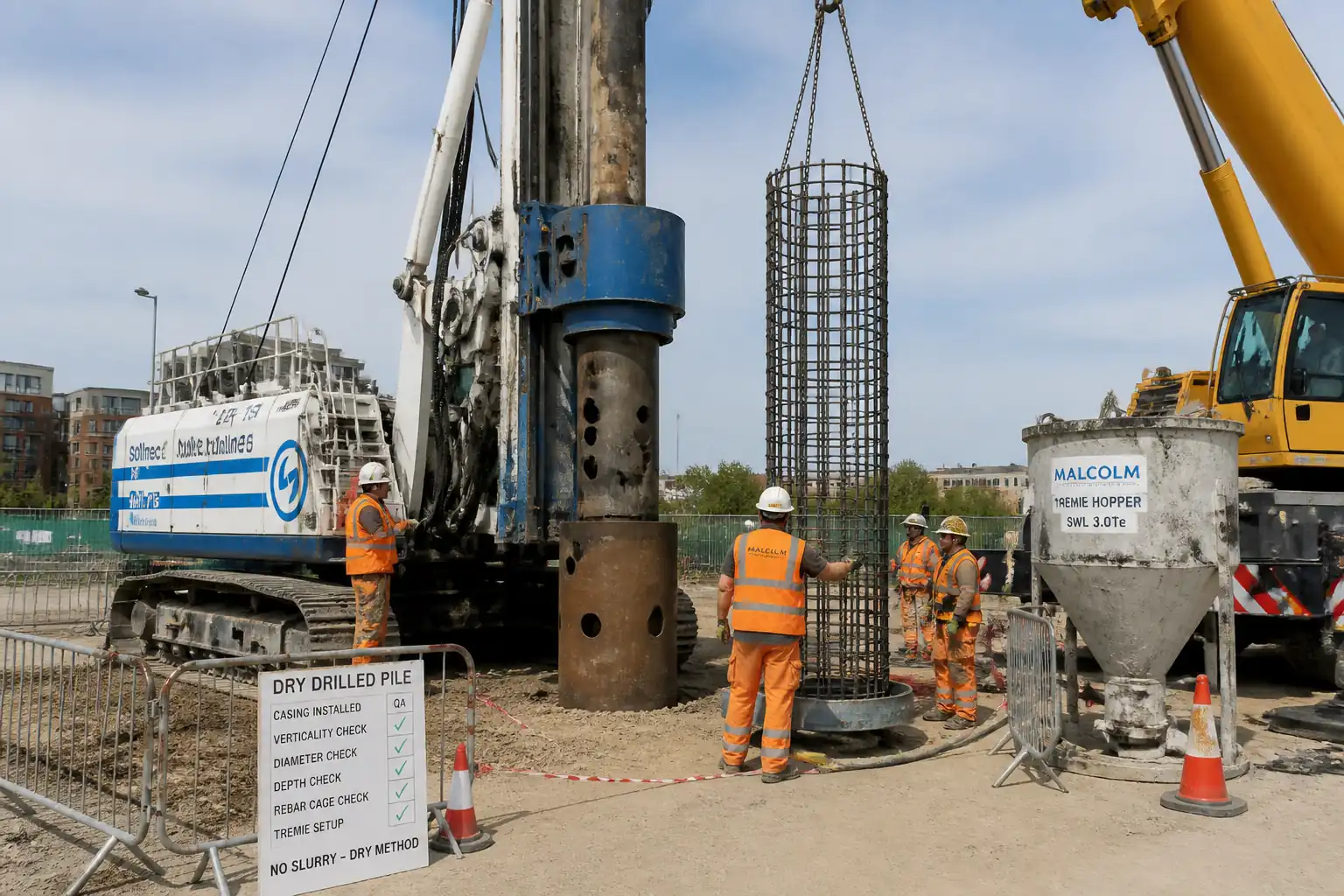
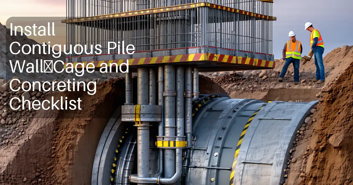
| 6 | Reinforcement cage installation | Lift and insert reinforcement cage centrally into the fresh concrete immediately after sufficient concrete has been placed to support the cage. Use centralizers to maintain cover. If vibratory consolidation is specified, use an internal vibratory poker with low amplitude and short duration to seat cage and release trapped air. Typical vibration: short bursts 5–15 s and withdraw slowly; avoid sustained high amplitude to prevent segregation. | Piling Supervisor / Banksman / Operator | Dimensional check & verticality during insertion |
| 7 | Pile head formation and cut-off | Allow concrete to reach acceptable initial set as per specification then excavate or trim pile head to design cut-off level. Form pile head and bent connection details where required. Use appropriate temporary support or casing as necessary. | Piling Supervisor / Site Team | Check cut-off level and surface quality |
| 8 | Post-pile survey & records | Carry out positional and verticality survey of completed pile and compile all logs, batch tickets, test results and ITP sign-offs for submission. | Surveyor / QA | Review and submit as-built data |
Safety Controls
- Personnel PPE: hard hat, high-visibility clothing, safety boots, gloves, eye protection and hearing protection as required. 2. Competency: only trained and certified operators to operate CFA rig and lifting equipment. 3. Exclusion zones around piling rig with barriers and signage; banksman to manage access. 4. Emergency procedures and contact details displayed on site. 5. Lifting operations to be planned with SWL checks, certified slings and lifting plan. 6. Machine guarding and lock-out procedures for maintenance. 7. Permit to work system for confined spaces and for hot works. 8. Control of concrete hazards: skin protection, wash stations and trained personnel for first aid of concrete burns. 9. Traffic management plan for deliveries; banksman to control plant interfaces. 10. Safe working distances for vibratory equipment; monitor vibration to avoid harm to personnel or nearby structures. 11. Avoid overhead power lines; check utilities before mobilising rig. 12. Noise and dust controls: use enclosures, water suppression and schedule noisy operations where appropriate. 13. Incident reporting and stop-work authority for any unsafe condition. 14. Continuous monitoring alarms to trigger work-stop and investigation for any exceedances in torque, pressure or unexpected ground response.
Environmental Controls
- Concrete washout: use dedicated bunded washout area; do not discharge to ground or drains. 2. Spill kits onsite and refuelling only on bunded areas away from watercourses. 3. Silt and runoff control with filter bags, settlement lagoons or lined bunding. 4. Dust suppression with water spraying where required. 5. Noise management: maintain plant, use mufflers and restrict noisy operations to agreed hours. 6. Waste concrete and packaging to be removed from site and disposed of by licensed waste carrier. 7. Protection of groundwater and surface water: immediate containment of any spill and notify Environment Agency / client if required. 8. Fuel and chemicals stored in bunded, secure compounds with MSDS available. 9. Minimise machine idling and optimise routeing for deliveries to reduce emissions. 10. Maintain records of environmental checks and incident reports.
Quality Assurance & Quality Control
- Hold points (ITP): Pre-mobilisation, plant calibration, first pile trial (if required), verification of continuous concrete placement parameters, reinforcement insertion, fresh concrete sampling and acceptance test results, post-pile survey. 2. Monitoring & recording: automated logs capturing time-stamped depth, torque, rpm, penetration, concrete pressure and flow; retain logs for submission with ITP. 3. Acceptance criteria: pile positional tolerance ±50 mm, verticality tolerance 1:200 (0.5%), concrete slump within specified range (±25 mm of target), concrete temperature within specified limits (as per spec), compressive strength target met at 28 days (allowable 28 day acceptance per contract). 4. Sampling frequency: sample fresh concrete for each pour/pile or per every 6 m3 of concrete placed (whichever is more frequent). Provide min. 3x150 mm cube samples per representative sample. 5. Non-conformance: log, stop works if major non-conformance, notify Engineer and follow corrective action procedure. 6. Calibration: instruments and pressure transducers calibrated before works and at regular intervals; calibration certificates retained. 7. Independent testing: use UKAS-accredited laboratory for compressive strength testing. 8. Records submission: supply monitoring logs, batch tickets, sample test results, survey reports and completed ITP to Engineer within agreed timeframe. 9. Trial piles: where specified, carry out trial pile(s) and review data prior to mass production.
Attachments
Attach the following documents to the method statement and ITP submission:
- Project piling drawings and pile schedule
- Geotechnical site investigation report
- Manufacturer manuals for CFA rig, pump and vibratory equipment
- Calibration certificates for torque sensors, pressure transducers and flow meters
- Concrete mix design and supplier certificate
- RAMS and permits to work
- Plant inspection and maintenance records
- Automated monitoring sample log template and example export
- Concrete test reports (slump, temperature and cubes)
- Trial pile report (if carried out)
- Environmental method notes (washout plan, spill plan)
All attachments to be version-controlled and provided in digital format (PDF) with a document register included in final submission.
This content is a read-only public reference. Download or customize to get an editable version.
ITP preview
The first inspection activities from the linked ITP for CFA Piling Method Statement — Auger Drilling, Continuous Concrete Placement & Cage Installation:
| Activity | Inspection / Test | Acceptance Criteria | Responsibility | Record |
|---|---|---|---|---|
| Pre-mobilisation review | Check method statement, RAMS, plant certificates and ITP distributed | All documents approved and personnel briefed | Piling Manager | Document register, toolbox talk attendance sheet |
| Plant & instrumentation calibration | Calibration certificates checked for rig torque sensor, pressure transducer and flow meter | Calibration valid and logged | Plant Engineer / QA | Calibration certificates, commissioning checklist |
| Set-out verification | Confirm pile centre coordinates and mark on ground prior to drilling | Position within ±50 mm of design | Surveyor | Set-out check sheet, survey printout |
Showing 3 of 8 inspection activities. View full ITP →
Related Inspection and Test Plan
An Inspection and Test Plan (ITP) is available for CFA Piling Method Statement — Auger Drilling, Continuous Concrete Placement & Cage Installation. The ITP defines the inspection activities, acceptance criteria, hold and witness points, responsible parties, and records required to verify the work described in this method statement.
View the CFA Piling Method Statement — Auger Drilling, Continuous Concrete Placement & Cage Installation ITP →Frequently asked questions
Continue with related Quollnet resources connected to this method statement.