Perform Jet Grouting: Monitor Rates, Diameter, and Strength
Definition: Perform jet grouting with this QA/QC checklist for field teams, engineers, and inspectors, standardizing monitoring of pump pressures, rotation/withdrawal rates, column diameter checks, and compressive strength verification.
- Define parameter windows from trials and control production in real time.
- Track pressures, flow, rotation, and withdrawal with calibrated instruments.
- Verify column diameter and UCS strength for acceptance and as-builts.
- Interactive, commentable, and export with QR code for secure sign-off.
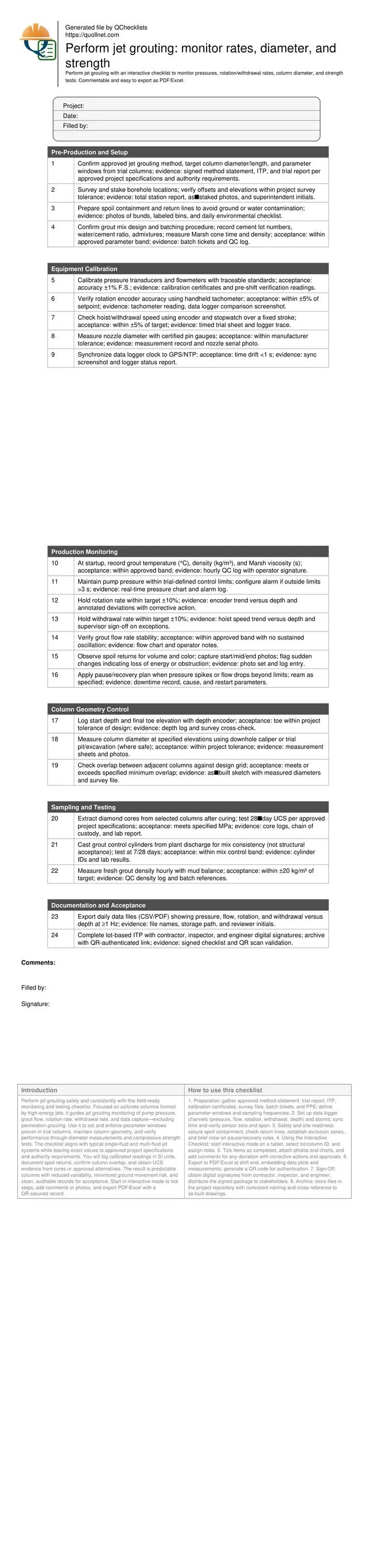
Perform jet grouting safely and consistently with this field-ready monitoring and testing checklist. Focused on soilcrete columns formed by high-energy jets, it guides jet grouting monitoring of pump pressure, grout flow, rotation rate, withdrawal rate, and data capture—excluding permeation grouting. Use it to set and enforce parameter windows proven in trial columns, maintain column geometry, and verify performance through diameter measurements and compressive strength tests. The checklist aligns with typical single-fluid and multi-fluid jet systems while leaving exact values to approved project specifications and authority requirements. You will log calibrated readings in SI units, document spoil returns, confirm column overlap, and obtain UCS evidence from cores or approved alternatives. The result is predictable columns with reduced variability, minimized ground movement risk, and clean, auditable records for acceptance. Start in interactive mode to tick steps, add comments or photos, and export PDF/Excel with a QR-secured record.
- Use trial columns to establish parameter windows for pump pressure, flow, rotation, and withdrawal. Then apply automated monitoring and alarms to hold production within the approved band, minimizing variability, collapse risk, and off-target energy while capturing defensible evidence for acceptance.
- Real-time data logging with calibrated sensors (pressure, flow, rotation encoder, hoist speed) produces depth-referenced charts. These records support quick intervention, post-shift QA review, and transparent handover to stakeholders, improving productivity and reducing rework on dense grids of soilcrete columns.
- Verification combines geometry checks and mechanical performance. Measure column diameter at specified elevations and confirm overlaps per design. Extract and test cores for 28-day UCS or perform approved in-situ alternatives, ensuring the installed elements meet project specifications and authority requirements for long-term reliability.
- Interactive online checklist with tick, comment, and export features secured by QR code.
Pre-Production and Setup
Equipment Calibration
Production Monitoring
Column Geometry Control
Sampling and Testing
Documentation and Acceptance
Trial Columns and Parameter Windows
Successful jet grouting begins with well-documented trial columns to establish parameter windows for pump pressure, grout flow, rotation rate, withdrawal speed, and grout properties. Run controlled trials in representative soils, then core or excavate to confirm column diameter, shape, and uniformity. From these results, define upper/lower control limits and automatic alarms for the data logger so operators can maintain energy input and avoid hydraulic fracturing or insufficient cutting. Calibrate pressure and flow sensors with traceable standards and verify rotation/withdrawal measurement accuracy before production. Capture spoil return characteristics and set clear pause/recovery rules if returns change abruptly. The trial report becomes the reference for acceptance bands, ensuring every production column is built under known, repeatable conditions. Document the approved mix design, anticipated Marsh cone time and density, and expected performance at key depths. This groundwork limits variability, shortens learning curves, and produces reliable soilcrete columns without resorting to permeation grouting approaches.
- Establish control limits from confirmed trial column performance.
- Calibrate sensors and encoders with traceable certificates.
- Record grout density and viscosity target bands.
- Define pause/recovery rules for abnormal returns.
Real-Time Production Monitoring
During production, maintain the machine within the approved parameter windows. The data logger should record pressure, flow, rotation, withdrawal, and depth at a minimum 1 Hz rate, synchronized to GPS/NTP time. Configure alarms to trigger when limits are exceeded for more than a few seconds, prompting the operator to pause, ream, or adjust. Verify stability of flow and pressure to ensure consistent energy delivery, and continuously observe spoil returns for signs of obstructions or ground loss. Keep a running QC log of grout temperature, density, and Marsh time at set intervals. For each column, annotate any deviations with the corrective action taken and outcome. This disciplined, evidence-based approach allows supervisors to spot trends, stop errors early, and protect adjacent structures from heave or voiding. It also creates clean records that underpin acceptance decisions and defend production choices during audits or technical reviews.
- Record all key channels depth-referenced at ≥1 Hz.
- Use alarms for timely intervention and recovery.
- Track spoil returns for quality and volume shifts.
- Log corrective actions for any deviation.
Column Verification and Strength Testing
Verification confirms that installed columns meet geometry and mechanical targets. Measure diameter at specified elevations using downhole calipers or safe trial pits where feasible. Update as-built grids to confirm overlaps and edge alignment. Extract cores from selected columns to test 28‑day UCS; combine with grout control cylinder testing for mix consistency trending. Where coring is impractical, propose approved in-situ alternatives (e.g., borehole imaging or penetrometer correlations) per approved project specifications and authority requirements. Acceptance focuses on meeting design diameter tolerances, maintaining overlap percentages, and achieving the specified UCS. Consolidate all evidence in a daily package of depth-referenced plots, measurement sheets, photos, and lab reports. This closes the loop from monitoring to proof of performance, enabling confident sign-off and reducing the risk of latent defects.
- Measure diameter at defined elevations and locations.
- Confirm overlaps meet design minima in the grid.
- Test cores for 28‑day UCS per specifications.
- Consolidate plots, photos, and lab reports daily.
How to Use This Jet Grouting Monitoring Checklist
- Preparation: gather approved method statement, trial report, ITP, calibration certificates, survey files, batch tickets, and PPE; define parameter windows and sampling frequencies.
- Set up data logger channels (pressure, flow, rotation, withdrawal, depth) and alarms; sync time and verify sensor zero and span.
- Safety and site readiness: secure spoil containment, check return lines, establish exclusion zones, and brief crew on pause/recovery rules.
- Using the Interactive Checklist: start interactive mode on a tablet, select lot/column ID, and assign roles.
- Tick items as completed, attach photos and charts, and add comments for any deviation with corrective actions and approvals.
- Export to PDF/Excel at shift end, embedding data plots and measurements; generate a QR code for authentication.
- Sign-Off: obtain digital signatures from contractor, inspector, and engineer; distribute the signed package to stakeholders.
- Archive: store files in the project repository with consistent naming and cross-reference to as-built drawings.
Call to Action
- Start Checklist Tick off tasks, leave comments on items or the whole form, and export your completed report to PDF or Excel—with a built-in QR code for authenticity.
- Download Excel - Jet Grouting Monitoring & Testing Checklist
- Download PDF - Jet Grouting Monitoring & Testing Checklist
- View Image - Jet Grouting Monitoring & Testing Checklist
Cite & Embed
“Jet Grouting Monitoring & Testing Checklist by Quollnet”
with a link to
this source page.

FAQ
Question: How do we select control limits for pressure, flow, rotation, and withdrawal?
Question: What field cues suggest loss of energy or obstruction during jet grouting?
Question: How can I verify column diameter without open excavation?
Question: Why test cores if grout cylinders already meet strength targets?
Related Articles
Broader reading and guidance connected to this checklist topic.


Master Construction Project Cashflow With Cashflowpot


Related Checklists
Keep the workflow moving with nearby templates chosen from similar checklist content.