
Method Statement – Vibro-Compaction Works for Granular/Sandy Soils – Method Statement
AI-assisted method statement with matching ITP, PDF download, and Excel export.
More than a static template
Unlike a downloadable Word or PDF template, this method statement is an AI-assisted editable starting point connected directly to a matching Inspection and Test Plan. Every section is structured, project-adaptable, and ready to export.
- AI-assisted drafting — Customize every section with AI for your specific project scope.
- Linked ITP — A matching inspection and test plan is generated alongside the method statement.
- Multiple export formats — Download as a formatted PDF or editable Excel spreadsheet.
- Editable starting point, not a final document — Review, verify, and adjust all content against your project requirements before use.
Static template vs. Quollnet workflow
| Feature | Static template | Quollnet |
|---|---|---|
| Project-specific content | Manual fill-in required | AI-assisted customization |
| Linked ITP | Separate document, no link | Matching ITP included |
| Export formats | Usually PDF only | PDF and Excel |
| Structured sections | Free-form layout | 13 standardized sections |
| Saved to your account | Local file only | Cloud-saved, reusable |
| Content accuracy | You verify everything | AI-assisted, you still verify |
| Cost | Often free but time-intensive | Free to customize and download |
What you can customize
When you save this method statement to your account, every section becomes editable. The following 13 sections are included:
- Scope — Defines the activity and its boundaries.
- References — Standards, specifications, and drawings.
- Responsibilities — Roles and accountabilities.
- Resources — Labour, plant, and equipment summary.
- Materials — Materials and compliance requirements.
- Equipment — Tools and equipment details.
- Prerequisites — Hold points and pre-conditions.
- Method sequence — Step-by-step construction sequence.
- Safety controls — HSE risk controls and PPE.
- Environmental controls — Environmental mitigation measures.
- QA/QC — Quality inspection and test requirements.
- ITP — Inspection and Test Plan table (has its own page).
- Attachments — Referenced drawings and documentation.
Why this method statement is used
This method statement is used to define and communicate the approved procedure for carrying out method statement – vibro-compaction works for granular/sandy soils on site. It ensures the work is planned in advance, the correct resources and controls are in place, and all personnel understand responsibilities, sequence, quality requirements, and safety controls before work begins. It aligns site execution with the documented scope and acceptance expectations.
Who uses this method statement
This method statement is used by contractors, site supervisors, project engineers, QA/QC engineers, HSE officers, consultants, and client representatives. It serves as a shared reference for planning, execution, supervision, inspection, and approval of the activity on site.
When it is prepared and submitted
The method statement is prepared before the work activity starts and submitted as part of the pre-construction documentation package for review and approval.
Who reviews or approves it
The method statement is usually submitted to the client representative, consultant, resident engineer, or project management consultant for review and approval before the work commences.
Important approval note
This method statement is an AI-assisted editable starting point, not a pre-approved document. Before use on any project, all content must be reviewed and approved by the relevant parties (superintendent, principal contractor, or client representative) in accordance with your contract and project quality plan.
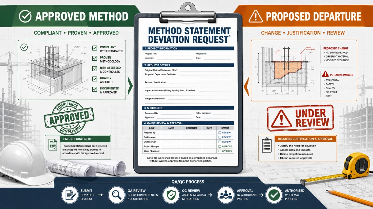
For example: if your specification requires a departure from a referenced standard, that departure must be documented and approved separately — this method statement will not capture that automatically. Always verify against your applicable drawings, specifications, and regulatory requirements.
Method statement content
Scope
Purpose
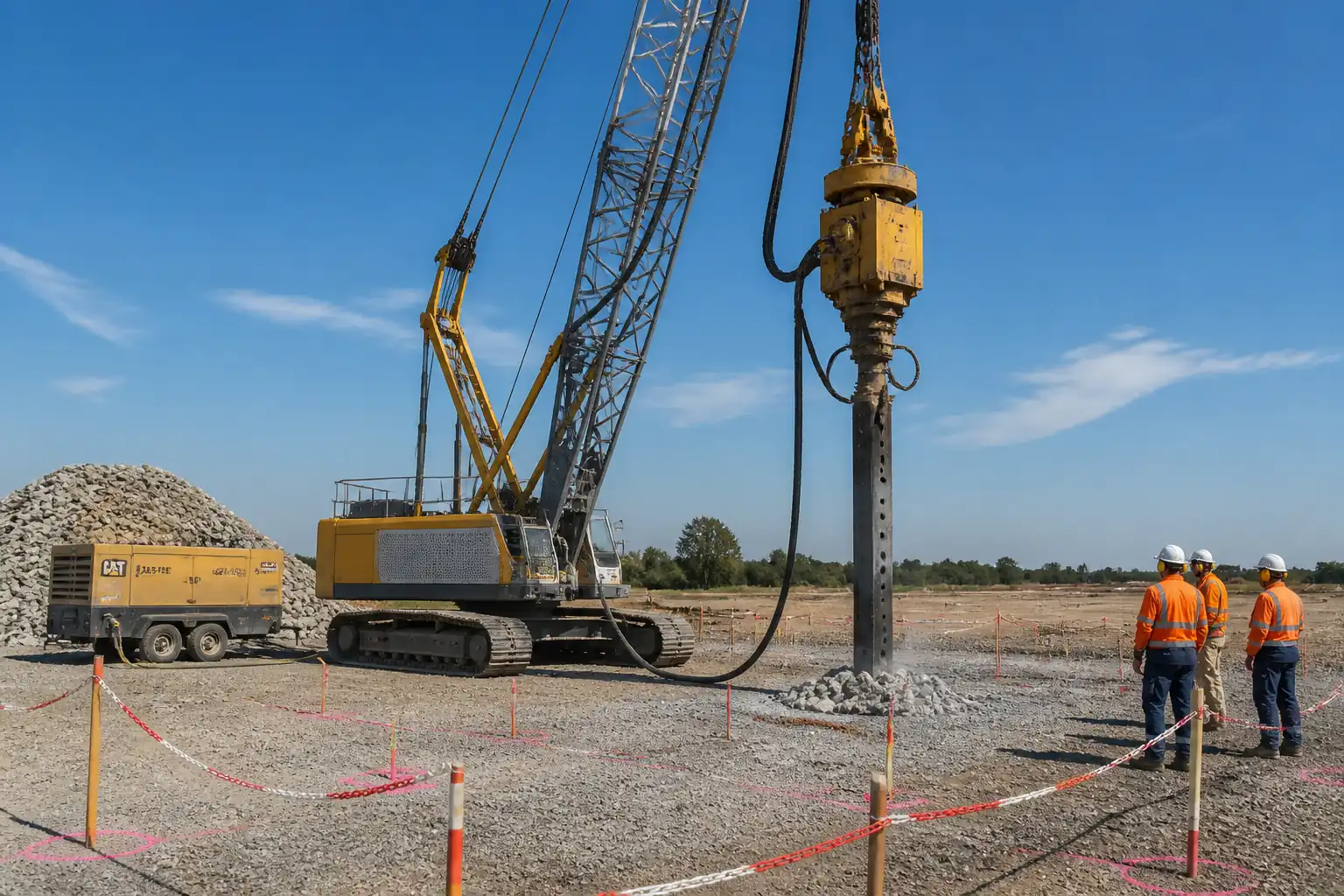
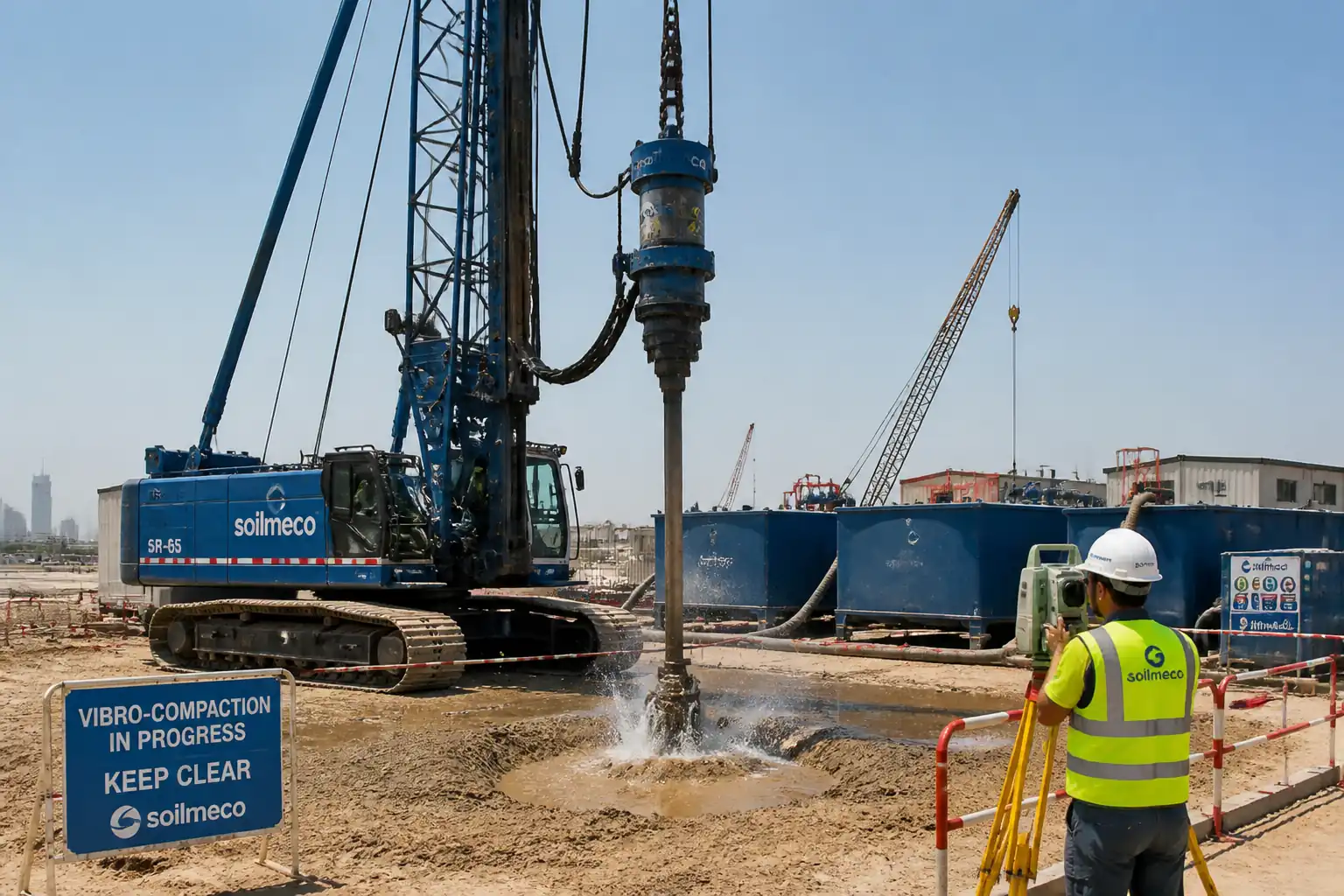
Provide the procedure to execute vibro-compaction (deep vibratory compaction) for densifying loose to medium-dense granular or sandy soils to reduce settlement and liquefaction potential, increase bearing capacity, and improve stiffness.
Extent
- Treatment of designated plan areas to the specified design depth using downhole vibroflot with water jetting.
- Establishment of compaction grid, trial area calibration, production compaction, and rework (if required).
- Post-treatment verification by CPT and/or SPT, and settlement monitoring.
Key Performance Objectives
- Achieve target relative density Dr (typ. ≥ 65–80% [Verify per project specifications]).
- Meet post-treatment CPT qc and/or SPT N60 criteria at specified depths.
- Demonstrate acceptable residual settlements and differential movements per design.
Exclusions
- Vibro-replacement (stone columns) and grouting (not applicable unless instructed).
- Treatment of cohesive or high-fines soils not suitable for vibro-compaction (fines content threshold to be confirmed by the geotechnical design).
References
| Document Type | Reference / Number | Revision | Notes |
|---|---|---|---|
| Standard | BS EN 1997-1/2 | ||
| Standard | ISO 22476-1 / ASTM D5778 | Select standard per project specification. | |
| Standard | ISO 22476-3 / ASTM D1586 | ||
| Standard | ASTM D4253 / ASTM D4254 | ||
| Standard | BS 5228 (Noise) / BS 7385 (Vibration) | Local limits to be verified. | |
| Standard | ISO 18674 (Series) | ||
| Guideline | ISO 17123 (as applicable) / Project Survey Specs | Use project survey specification where provided. |
Responsibilities
| Role | Responsibility | Name / Party |
|---|---|---|
| Project Manager | Contractor | Contractor |
| Geotechnical Engineer | Contractor | Contractor |
| Site Manager | Contractor | Contractor |
| QA/QC Engineer | Contractor | Contractor |
| HSE Manager | Contractor | Contractor |
| Land Surveyor | Contractor | Contractor |
| Laboratory/Field Testing | Third Party | Independent |
Resources
| Resource Type | Description | Quantity | Remarks |
|---|---|---|---|
| Personnel | 1 | ||
| Personnel | 1–2 [Verify] | ||
| Personnel | 1 | ||
| Personnel | 1 per shift [Verify] | ||
| Personnel | 1 per rig | ||
| Personnel | 2 | ||
| Personnel | 1 | ||
| Personnel | 1 each (shared) | ||
| Personnel | 1 team |
Materials
| Material | Specification / Grade | Quantity | Remarks |
|---|---|---|---|
| Water | pH 6–9 [Verify] | 150–250 m³/h per rig [Verify] | |
| Sand | USCS: SP–SW preferred | As required | |
| Survey accessories | Per ISO 18674 / Project specs | As required |
Equipment
| Equipment | Capacity / Type | Quantity | Inspection Required |
|---|---|---|---|
| Vibroflot | Penetration to design depth | 1–2 rigs [Verify] | Yes |
| Crane/Leader | Per rig mass + dynamic effects [Verify] | 1 per vibroflot | Yes |
| Pump | As above | 1 duty + 1 standby per rig | Yes |
| Power Pack | Per OEM | As required | Yes |
| Datalogger/Survey/CPT | 1 set per rig + CPT/SPT units | Yes | |
| Environmental | As required | Yes |
Prerequisites
Approvals and Documentation
- Approved method statement, risk assessment, lifting plan, and ITP. [Hold]
- Design package specifying treatment depth, target Dr/qc/N60, and rework criteria. [Hold]
- Utility survey, mark-out, and Permit-to-Dig/Excavate. [Hold]
- Jetting water source and discharge permit including turbidity/pH limits. [Verify per project HSE plan and local regulations]
- Access/platform certificate: platform CBR ≥ 5% or bearing capacity ≥ 200 kPa; gradient ≤ 3%; thickness/compaction verified. [Verify]
- Calibration certificates: gauges, flow meters, RCDs, depth encoders, data loggers, CPT/SPT rigs.
Site Readiness
- Grid coordinates issued; primary/secondary control established and verified.
- Exclusion zones and traffic management set; lighting for night shifts.
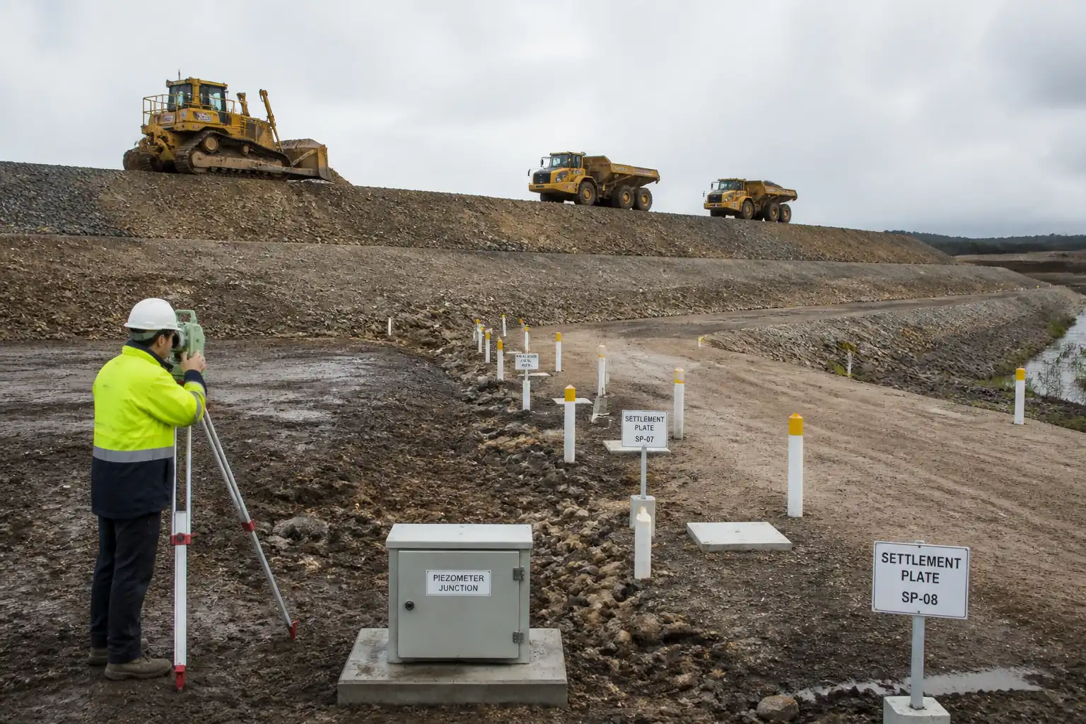
- Baseline monitoring installed (settlement plates/benchmarks) and initial readings recorded.
- Pre-treatment CPT/SPT locations approved and executed where required.
- Trial area (e.g., 20 m × 20 m) demarcated for parameter calibration. [Witness]
Suitability of Ground for Vibro-Compaction
- Predominantly granular soils with low plasticity; fines content typically <10–15% passing 0.075 mm sieve; PI ≈ 0. [Verify per design].
- Groundwater level known; sufficient saturation anticipated to facilitate rearrangement of particles during vibration.
Method Sequence
| Step | Activity | Description | Responsibility | Inspection / Hold Point |
|---|---|---|---|---|
| 1 | Mobilization & Induction | Mobilize rigs, pumps, power; conduct site induction, toolbox talks, and equipment pre-use inspections. | Site Manager / HSE | HSE inspection |
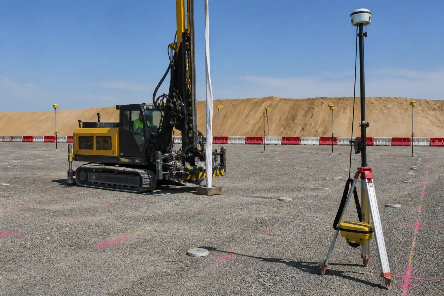
| 2 | Survey Control & Grid Set-out | Set out grid using RTK/GNSS or total station; mark points with stakes/paint; typical spacing 2.0–4.0 m on triangular or square grid [Verify per design]. Tolerance: plan position ±0.15 m; level ±0.02 m. | Surveyor | Witness |
| 3 | Pre-Treatment Testing (Baseline) | Execute CPT and/or SPT at agreed locations prior to production works. | Testing Agency | Witness |
| 4 | Trial Area Calibration | Select 20×20 m area; vary parameters (jet pressure, flow, dwell time, pull rate, power draw) to optimize. Record: jet pressure 8–15 bar; flow 150–250 m³/h; pull rate 0.2–0.5 m/min; step increment 0.5 m with 20–60 s dwell. Confirm design depth achieved and surface stability. Post-trial CPT/SPT to confirm improvement. | Geotechnical Engineer | Hold (approval of parameters) |
| 5 | Penetration to Design Depth | Start jetting; vibrate and advance vibroflot vertically to target depth (±0.5 m). Maintain verticality within ±2°. Monitor amperage/power and penetration rate. | Vibroflot Operator | Surveillance |
| 6 | Bottom Dwell and Base Densification | At base, maintain vibration 60–120 s to initiate densification; reduce jet flow to minimal required for particle rearrangement. | Operator/Geotech | Surveillance |
| 7 | Stepwise Extraction (Compaction) | Withdraw in 0.5 m steps with 20–60 s dwell per step while modulating jet to maintain saturation but prevent excessive loosening. Target pull rate 0.2–0.5 m/min [Verify]. Maintain crater filled with sand/water to avoid voiding and sidewall collapse. | Operator | Surveillance |
| 8 | Top Zone Re-Compaction | Perform slow pass in upper 3–5 m to counteract loosening due to upward energy; minimal jetting. Backfill surface crater with clean sand as required and compact surface. | Operator/Site Crew | Surveillance |
| 9 | Grid Progression | Proceed to next grid point according to pattern; maintain minimum spacing-to-influence overlap per design; typical overlap 10–20% of influence radius [Verify]. | Site Manager | Surveillance |
| 10 | Interim Verification (Spot CPTs) | Execute selective CPTs at agreed frequency during production to confirm parameter adequacy; adjust if shortfall observed. | Testing Agency/Geotech | Witness |
| 11 | Post-Treatment Testing | Perform CPT at min. frequency 1 per 800–1,200 m², SPT in selected boreholes 1 per 2,000–3,000 m² or as specified. Depth: full treatment depth + 2 m. Space tests to represent edges and interiors. [Verify per project]. | Testing Agency | Witness |
| 12 | Rework (If Required) | Where criteria not met, perform additional passes or reduce spacing locally; retest until acceptance or escalation per NCR process. | Geotechnical Engineer | Witness |
| 13 | Settlement Monitoring | Read settlement plates/benchmarks: daily during production within influence zone; weekly for 4–8 weeks post-works or as specified. Trigger levels set per design; investigate if exceeded. | Surveyor/Geotech | Witness |
| 14 | As-Builts and Demobilization | Compile as-built grid coordinates, depths, parameters, and test results; reinstate surfaces; demobilize plant. | Project Manager | Review |
Health, Safety and Environment – Task-Specific Safety Controls
Principal Hazards and Controls
1) Underground utility strike (penetrating vibroflot and jetting)
- Consequence: Electrocution, explosion, flooding, service outage.
- Engineering/Procedural Controls: Up-to-date utility plans; GPR/CAT scanning; marked exclusion; hand-dug trial pits at each first-row grid point; Permit-to-Dig; max penetration limited until clearance confirmed.
- Required PPE: Dielectric gloves when probing; helmet, eye protection, safety boots.
- Collective Measures: Physical barriers/spotters; lock-out of known live services.
- Inspection/Permits/Supervision: Permit-to-Dig signed by Supervisor daily; HSE Officer verification; records retained. [Verify per project HSE plan and local regulations]
2) Crane/rig instability and platform failure
- Consequence: Overturning, crushing, fatalities.
- Controls: Geotechnical platform design; CBR ≥ 5% or plate bearing ≥ 200 kPa; thickness and compaction checks; track mats where soft; daily plant walkaround; wind limits per OEM (e.g., ≤ 12 m/s for lifting).
- PPE: Helmets, hi-vis, steel-toe boots.
- Collective Measures: Exclusion zone (radius ≥ swing radius + 5 m); banksman control; slew restrictors.
- Inspection/Permits: Platform certificate; lifting plan and pre-lift checklist; crane certification in date.
3) High-pressure water jetting and hose whip
- Consequence: Laceration, injection injury, eye damage.
- Controls: Rated hoses and whip-checks; pressure regulators/relief valves; guards; depressurize before disconnect; colored strobe for pump running; minimum 2 m exclusion around hoses/jets.
- PPE: Face shield + goggles, waterproof gloves, cut-resistant gauntlets, waterproof clothing.
- Collective Measures: Physical barriers; emergency stop within reach; signage.
- Inspection/Permits: Pressure test certificates; daily hose inspection log; permit for high-pressure jetting.
4) Electrical hazards (vibroflot power cables, generators)
- Consequence: Electric shock, arc flash.
- Controls: RCD protection; IP67 connectors; cable routing away from water pathways; lock-out/tag-out during maintenance; residual current tests.
- PPE: Electrical gloves (as needed), dielectric boots for maintenance, standard PPE.
- Collective Measures: Barriers around distribution boards; dry platforms for gensets; spill containment.
- Inspection/Permits: Electrical test sheets; competent electrician; permit-to-work for electrical tasks.
5) Struck-by / caught-between during lifting and rigging
- Consequence: Serious injury or fatality.
- Controls: Certified slings/shackles; tag lines; no hands on load; defined communication; lift plan with load chart.
- PPE: Helmets with chin straps, gloves.
- Collective Measures: Exclusion zone; banksman authority to stop work.
- Inspection/Permits: Lifting permits; pre-lift checks; operator certification.
6) Open craters/soft ground after compaction
- Consequence: Falls, equipment bogging.
- Controls: Immediate backfilling/leveling; barricade until stable; proof-rolling where specified.
- PPE: Standard PPE; fall protection if near edges >2 m deep.
- Collective Measures: Edge protection, signage.
- Inspection/Permits: Supervisor sign-off before traffic.
7) Noise and ground-borne vibration
- Consequence: Hearing loss, nuisance, potential building damage.
- Controls: Maintain plant; acoustic shrouds where feasible; schedule noisy works day-time; monitor LAeq and PPV per BS 5228/BS 7385.
- PPE: Hearing protection (SNR ≥ 25 dB) and vibration-damping gloves for operators.
- Collective Measures: Noise barriers; community notice.
- Inspection/Permits: Noise/vibration monitoring logs; complaint register.
8) Slurry/sediment ejection and slip hazards
- Consequence: Eye injury, slips, environmental discharge.
- Controls: Splash guards; graded working area draining to settlement tanks; housekeeping.
- PPE: Eye/face protection, waterproof boots.
- Collective Measures: Silt fencing; bunded discharge lines.
- Inspection/Permits: Water discharge permit; turbidity spot checks.
9) Night/low-visibility operations
- Consequence: Vehicle/personnel interface incidents.
- Controls: Task lighting ≥ 50 lux general / ≥ 200 lux at workface [Verify]; reflective PPE; traffic plan.
- PPE: Hi-vis Class 3.
- Collective Measures: Dedicated spotters; reduced speeds.
- Inspection/Permits: Night-work permit; lighting checks.
10) Heat stress/dehydration (high water use environment)
- Consequence: Illness, reduced performance.
- Controls: Work/rest regime; hydration points; shade; acclimatization.
- PPE: Sun protection, breathable PPE.
- Collective Measures: Cool-down area.
- Inspection/Permits: HSE monitoring; first aid available.
Environmental Controls
Water Management and Discharge
- Provide lined settlement tanks/bays sized for ≥ 30 minutes retention at peak flow; fit baffles and silt bags on outlets.
- Monitor turbidity (NTU) and pH per permit; targets e.g., turbidity rise ≤ 50 NTU over background; pH 6–9. [Verify per permit]
- Use flow meters on discharge and makeup water; log daily volumes; prevent uncontrolled runoff.
Groundwater and Adjacent Asset Protection
- Control jetting to avoid excessive uplift or ground loss; observe for heave/settlement at boundaries.
- Where sensitive structures exist, install vibration geophones and settlement points; PPV trigger values typically 5–10 mm/s at foundations [Verify]. Actions: reduce energy/increase spacing or pause.
Noise and Air Quality
- Apply BS 5228 guidance; set project-specific noise limits; use temporary barriers and schedule high-noise works.
- Dust control for access roads: water bowsers, speed limits ≤ 20 km/h; cover stockpiles.
Waste and Spills
- Classify silted water and sediments; dispose via licensed facilities; keep manifests.
- Bund all fuels/chemicals at 110% of largest container; spill kits at pumps/generators; train crews in spill response.
Ecology and Community
- Avoid jetting near watercourses without silt curtains and permits; inspect daily for turbidity plumes.
- Advance notification to neighbors; maintain complaint log and response actions.
QA/QC Requirements
General
- Implement ITP with defined Hold/Witness points. All instruments must have valid calibration certificates (≤ 12 months or per manufacturer).
- Maintain daily rig logs capturing: point ID, coordinates, start/finish times, penetration depth, jet pressure/flow, amperage/power draw, dwell times, pull rates, remarks.
Tolerances and Operating Parameters
- Grid point location: ±0.15 m.
- Verticality: ±2° from vertical.
- Depth of treatment: to design depth ±0.5 m.
- Jet pressure/flow (trial to set): nominal 8–15 bar and 150–250 m³/h; maintain within ±10% of approved values.
- Step extraction: 0.5 m increments with 20–60 s dwell; average pull rate 0.2–0.5 m/min.
Verification Testing and Acceptance
- CPT Acceptance (where specified):
- Achieve minimum qc at target depths, e.g., qc ≥ 8–12 MPa in upper treated zone and ≥ 12–18 MPa at depth bands as designed [Verify per design and soil type].
- Demonstrate improvement factor (post/pre) typically ≥ 1.5–2.0 where baseline available. [Verify]
- SPT Acceptance (where specified):
- Corrected N60 values meeting target bands, e.g., N60 ≥ 25 in upper zone and ≥ 30–40 at depth [Verify].
- Relative Density (if used): Dr ≥ 65–80% [Verify]. Compute from ASTM D4253/D4254 index densities and in situ density.
- Test Frequency (minimum): CPT 1 per 800–1,200 m²; SPT 1 per 2,000–3,000 m² or as directed. Edge and interior coverage required.
Rework Criteria
- Any test location failing targets triggers either: (a) two additional nearby tests to define extent; and (b) re-compaction with reduced spacing and/or altered parameters. Re-test until conformity or escalate via NCR.
Records and Deliverables
- As-built grid with coordinates and achieved depths.
- Rig parameter time histories per point.
- CPT/SPT reports (raw + interpreted), monitoring reports, nonconformance and corrective action reports.
- Final summary with compliance matrix against acceptance criteria.
Attachments
- Sample Daily Vibro-Compaction Log (point-based parameter sheet).
- Trial Area Parameter Optimization Report template.
- CPT/SPT Location Plan and Logs (pre- and post-treatment).
- Settlement Monitoring Procedure and Readings Log.
- Working Platform Certificate Template.
- Permit-to-Dig form.
- Lifting Plan and Rigging Certificates.
- Calibration Certificates (pressure/flow gauges, encoders, RCDs).
- Noise/Vibration Monitoring Plan and Results.
- Nonconformance/Corrective Action Form.
- As-built Drawing Template and Compliance Matrix.
This content is a read-only public reference. Download or customize to get an editable version.
ITP preview
The first inspection activities from the linked ITP for Method Statement – Vibro-Compaction Works for Granular/Sandy Soils:
| Activity | Inspection / Test | Acceptance Criteria | Responsibility | Record |
|---|---|---|---|---|
| Method Statement, Risk Assessment, ITP Approval | Document check | Approved prior to works [Hold] | Contractor/Engineer | Approved MS/ITP/RAMS |
| Utility Clearance and Permit-to-Dig | GPR/CAT results; trial pits | Permit signed; services cleared [Hold] | Contractor/HSE | Permit-to-Dig; scan logs |
| Working Platform Certification | CBR/plate load; thickness check | Meets design capacity and level [Witness] | Contractor/Geotech | Platform certificate |
Showing 3 of 11 inspection activities. View full ITP →
Related Inspection and Test Plan
An Inspection and Test Plan (ITP) is available for Method Statement – Vibro-Compaction Works for Granular/Sandy Soils. The ITP defines the inspection activities, acceptance criteria, hold and witness points, responsible parties, and records required to verify the work described in this method statement.
View the Method Statement – Vibro-Compaction Works for Granular/Sandy Soils ITP →Frequently asked questions
Continue with related Quollnet resources connected to this method statement.