
Method Statement: Surcharging and Settlement Monitoring for Preloading of Soft Ground – Method Statement
AI-assisted method statement with matching ITP, PDF download, and Excel export.
More than a static template
Unlike a downloadable Word or PDF template, this method statement is an AI-assisted editable starting point connected directly to a matching Inspection and Test Plan. Every section is structured, project-adaptable, and ready to export.
- AI-assisted drafting — Customize every section with AI for your specific project scope.
- Linked ITP — A matching inspection and test plan is generated alongside the method statement.
- Multiple export formats — Download as a formatted PDF or editable Excel spreadsheet.
- Editable starting point, not a final document — Review, verify, and adjust all content against your project requirements before use.
Static template vs. Quollnet workflow
| Feature | Static template | Quollnet |
|---|---|---|
| Project-specific content | Manual fill-in required | AI-assisted customization |
| Linked ITP | Separate document, no link | Matching ITP included |
| Export formats | Usually PDF only | PDF and Excel |
| Structured sections | Free-form layout | 13 standardized sections |
| Saved to your account | Local file only | Cloud-saved, reusable |
| Content accuracy | You verify everything | AI-assisted, you still verify |
| Cost | Often free but time-intensive | Free to customize and download |
What you can customize
When you save this method statement to your account, every section becomes editable. The following 13 sections are included:
- Scope — Defines the activity and its boundaries.
- References — Standards, specifications, and drawings.
- Responsibilities — Roles and accountabilities.
- Resources — Labour, plant, and equipment summary.
- Materials — Materials and compliance requirements.
- Equipment — Tools and equipment details.
- Prerequisites — Hold points and pre-conditions.
- Method sequence — Step-by-step construction sequence.
- Safety controls — HSE risk controls and PPE.
- Environmental controls — Environmental mitigation measures.
- QA/QC — Quality inspection and test requirements.
- ITP — Inspection and Test Plan table (has its own page).
- Attachments — Referenced drawings and documentation.
Why this method statement is used
This method statement is used to define and communicate the approved procedure for carrying out method statement: surcharging and settlement monitoring for preloading of soft ground on site. It ensures the work is planned in advance, the correct resources and controls are in place, and all personnel understand responsibilities, sequence, quality requirements, and safety controls before work begins. It aligns site execution with the documented scope and acceptance expectations.
Who uses this method statement
This method statement is used by contractors, site supervisors, project engineers, QA/QC engineers, HSE officers, consultants, and client representatives. It serves as a shared reference for planning, execution, supervision, inspection, and approval of the activity on site.
When it is prepared and submitted
The method statement is prepared before the work activity starts and submitted as part of the pre-construction documentation package for review and approval.
Who reviews or approves it
The method statement is usually submitted to the client representative, consultant, resident engineer, or project management consultant for review and approval before the work commences.
Important approval note
This method statement is an AI-assisted editable starting point, not a pre-approved document. Before use on any project, all content must be reviewed and approved by the relevant parties (superintendent, principal contractor, or client representative) in accordance with your contract and project quality plan.
For example: if your specification requires a departure from a referenced standard, that departure must be documented and approved separately — this method statement will not capture that automatically. Always verify against your applicable drawings, specifications, and regulatory requirements.
Method statement content
Scope
Scope of Works
- Preloading (surcharging) of soft cohesive/organic/alluvial ground to accelerate primary consolidation prior to permanent works construction.
- Supply, placement, shaping, and staged increase of surcharge fill above design platform level to target degree of consolidation.
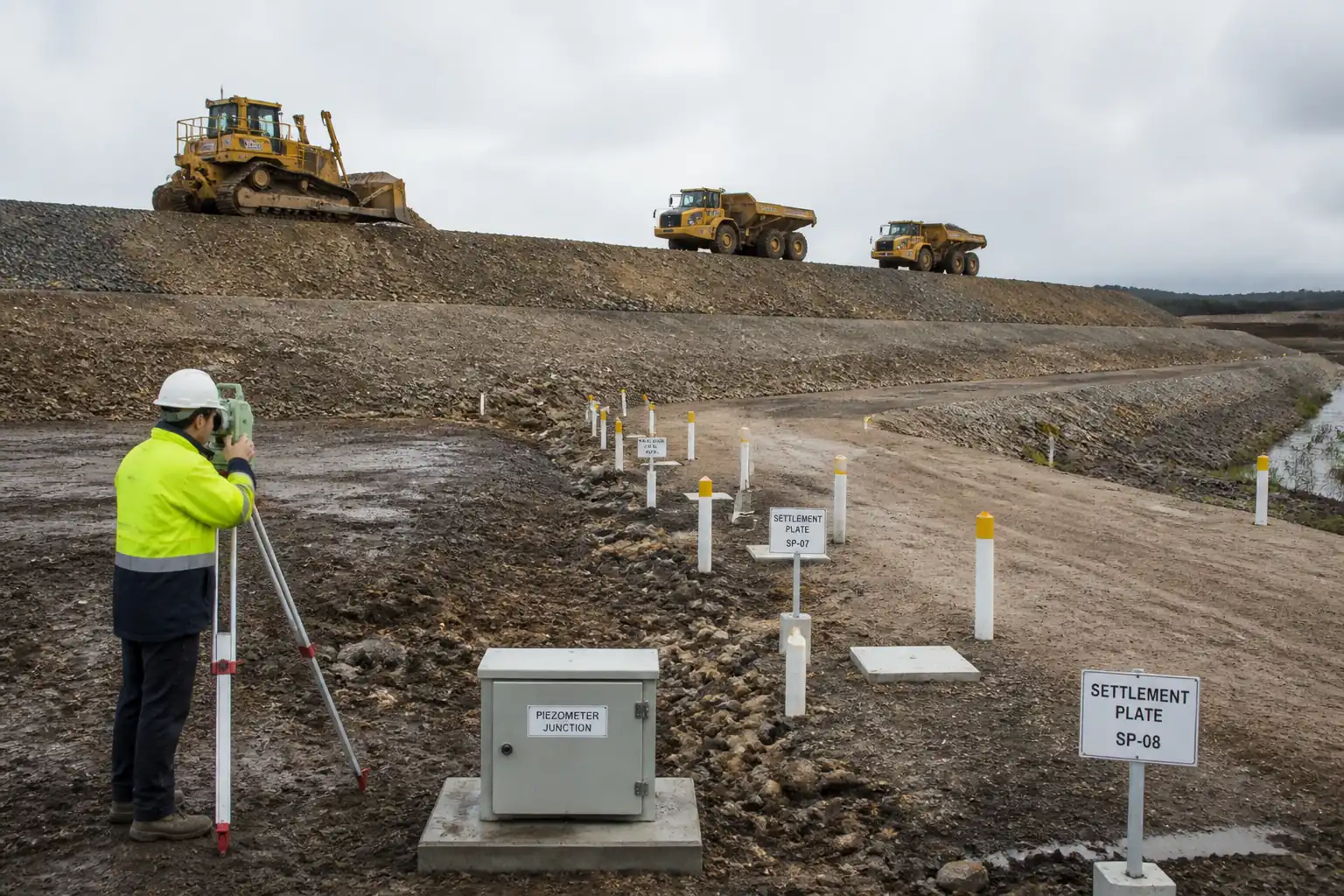
- Installation, surveying, protection, and monitoring of settlement plates (SPs) and piezometers (PZs) (standpipe and/or vibrating wire), including datum benchmarks and protective markers.
- Establishment of monitoring regime: frequencies, methods, data management, trigger levels, and reporting.
- Assessment of consolidation using settlement-time approaches (e.g., Asaoka, hyperbolic) and pore-pressure dissipation.
- Criteria and sequence for holding period at final surcharge, controlled removal of surcharge, verification of residual consolidation, and handover of the preloaded platform.
- Interfaces with earthworks, survey, geotechnical design, laboratory testing, drainage, and temporary works.
Exclusions
- Ground improvement by vertical drains, stone columns, or deep mixing (unless separately specified).
- Temporary works for adjacent structures not directly impacted by preload.
- Permanent drainage systems beyond temporary surface runoff control.
Key Assumptions [Verify per project specifications]
- Target degree of consolidation: U ≥ 90% at critical locations (settlement and pore-pressure indicators).
- Surcharge height: as per design (typically +10% to +30% over final platform load equivalence).
- Acceptance based on: rate of settlement ≤ 1 mm/day averaged over 7 consecutive days and ≥ 90% pore-pressure dissipation from peak at governing layers.
- Loading staged in lifts of 0.3–0.5 m with interim stability checks and monitoring.
- Fill compaction to trafficable condition suitable for plant (e.g., ≥ 90–95% MDD where specified) without inducing undue pore pressure.
- Side slopes and berms designed for stability; drainage maintained to prevent softening.
References
| Document Type | Reference / Number | Revision | Notes |
|---|---|---|---|
| BS EN 1997-1 (Eurocode 7), Geotechnical design — General rules | Use designer’s verified stability model for staged loading; partial factors per design basis [Verify]. | ||
| BS 6031: Code of practice for earthworks | Placement, compaction, drainage, and slope formation guidance. | ||
| ISO 18674-1: Monitoring by geotechnical instrumentation — General rules | Terminology, data quality, documentation. | ||
| ISO 18674-2: Monitoring — Piezometers | VWP and standpipe installation and performance assessment. | ||
| BS EN ISO 17892-5: Geotechnical investigation and testing — Laboratory testing of soil — Part 5: Incremental loading oedometer test | Alternative: ASTM D2435/D2435M. | ||
| ASTM D698 / ASTM D1557 (Standard/Modified Proctor) | Where project specifies degree of compaction for surcharge fill trafficability. | ||
| ISO 17123 (Field procedures for testing geodetic instruments) [General reference] | Use calibrated automatic/digital level with closed loops. |
Responsibilities
| Role | Responsibility | Name / Party |
|---|---|---|
| Geotechnical Designer | Geotechnical Designer | Designer |
| Site Manager | Contractor (Site Manager) | Contractor |
| Instrumentation Engineer/Technician | Instrumentation Specialist | Specialist |
| Land Surveyor | Surveyor | Contractor |
| QA/QC Engineer | QA/QC Engineer | Contractor |
| HSE Manager | HSE Manager | Contractor |
| Engineer | Engineer/Employer’s Representative | Engineer |
Resources
| Resource Type | Description | Quantity | Remarks |
|---|---|---|---|
| Labour | Coordinates field operations and staging. | 1 | |
| Labour | Spreading and trimming fill. | 2 | |
| Labour | Haul and tip fill in controlled locations. | 5 | |
| Specialist | Install/read SPs/PZs, data QA/QC. | 2 | |
| Specialist | Levelling and as-builts. | 1 crew |
Materials
| Material | Specification / Grade | Quantity | Remarks |
|---|---|---|---|
| Surcharge Fill | Meets BS 6031 and project spec; MDD/gradation per spec [Verify] | As per design volume | |
| Geotextile | EN ISO 10319 tensile properties [Verify] | As required | |
| Steel plate and pipe/rod | Corrosion-protected components [Verify] | Per monitoring layout | |
| Piezometer set | ISO 18674-2 compliant VWP; standpipe to ASTM D4750 practice [General] [Verify] | Per monitoring layout | |
| Cement-bentonite grout | Per manufacturer; k ≤ 1E-9 m/s [Verify] | As required |
Equipment
| Equipment | Capacity / Type | Quantity | Inspection Required |
|---|---|---|---|
| Dozer LGP | 15–25 t | 1–2 | Daily pre-use checks |
| ADT | 20–30 t | 3–8 | Daily pre-use checks |
| Roller | 8–12 t | 1 | Daily pre-use checks |
| Excavator | 20–30 t | 1 | Daily pre-use checks |
| Level/TS/GNSS | 1 set | Calibration per QA plan | |
| Lightweight rig | 1 | Rig inspection and permits | |
| VWP readout | Per VWP | Calibration check before use |
Prerequisites
Pre-Start Requirements
- Approved geotechnical design with: preload height, stage increments, slope/berm details, drainage, trigger levels, acceptance criteria, and TARP [Verify per project specifications].
- Baseline ground investigation data, consolidation parameters (Cc, Cv), undrained shear strength Su profile, groundwater regime, and stability assessment for each stage.
- Approved method statement, risk assessment, ITP, and permits [Verify per project HSE plan and local regulations].
- Survey control: establish minimum two stable benchmarks (BM) outside influence zone; initial readings for SPs/PZs recorded as zero datum.
- Materials approvals: source tests for fill (gradation, plasticity, moisture), compaction method statement, geotextile data sheets.
- Instrumentation layout drawing approved showing IDs, coordinates, ground elevations, target tip depths (for PZs), and protection details.
- Temporary drainage plan: perimeter drains, silt traps, temporary outfalls with treatment if required.
- Traffic management and haul route plan suitable for soft ground (CBR threshold for access or use of geotextile/geogrid if required) [Verify].
- Emergency response plan for instability, excessive settlement rate, or rapid pore-pressure rise.
- Calibration certificates for levels, VWPs, data loggers, and readout units within validity.
Method Sequence
| Step | Activity | Description | Responsibility | Inspection / Hold Point |
|---|---|---|---|---|
| 1 | Site Preparation and Access | Demarcate preload area, install exclusion zones, set haul routes on geotextile if needed, clear vegetation (minimal stripping on soft ground). | Contractor | HSE walkdown; survey BM established |
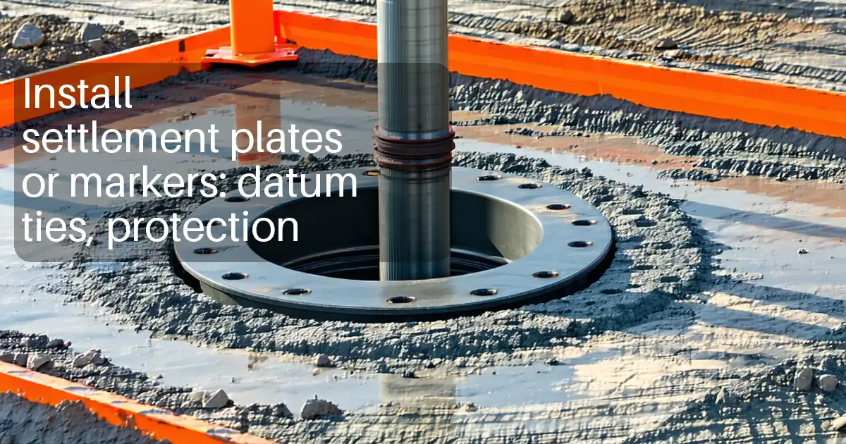
| 2 | Install Settlement Plates (SP) | Excavate shallow pocket to firm formation; place geotextile (if specified), seat 600×600 mm steel plate level; connect riser (pipe/rod) vertically; backfill and protect with small berm and marker posts. | Instrumentation Specialist | Engineer witness |
| 3 | Install Piezometers (Standpipe/VWP) | Advance small borehole or push-in to design depth; install filter tip at target horizon; seal with graded filter/bentonite seals to isolate zones; grout to surface; protect with steel cover and bollards; connect VWP cable to junction box/logger. | Instrumentation Specialist | Engineer witness |
| 4 | Baseline Readings | Take initial SP elevations (3 consecutive readings within 24 h) and PZ pore-pressure readings; establish zero time. | Instrumentation Specialist | QA/QC review |
| 5 | Stage 1 Fill Placement | Place surcharge in 0.3–0.5 m loose lifts; spread with LGP dozer; compact lightly to achieve trafficability without over-vibration; maintain side slopes (e.g., 1V:3H) and toe berm as designed. | Contractor | Compaction method check; slope inspection |
| 6 | Monitoring During Stage 1 | Record SP daily for first 3–7 days then 2–3/week; PZ readings daily for first 7 days then 2–3/week; plot time–settlement and time–pore-pressure curves; check triggers. | Instrumentation Specialist | Engineer review weekly |
| 7 | Stability Verification and Next Stages | Review settlement rate, PZ excess u, and slope condition; if within triggers, proceed with next 0.3–0.5 m lift(s). Pause if amber/red triggers exceeded; perform geotechnical check. | Contractor/Designer | Engineer approval prior to next stage |
| 8 | Reach Final Surcharge Level | Complete filling to design surcharge elevation; shape crown to shed water; maintain drains and safe access. | Contractor | Engineer inspection |
| 9 | Holding/Consolidation Period | Maintain final surcharge for specified duration or until criteria achieved. Continue monitoring: SP weekly; PZ 2–3/week initially then weekly when stable. Assess consolidation (Asaoka/hyperbolic) and degree of dissipation. | Instrumentation Specialist/Designer | Engineer periodic review |
| 10 | Approval to Remove Surcharge | Submit monitoring data and analysis; request Engineer approval to commence controlled removal. | Contractor | Engineer approval |
| 11 | Controlled Surcharge Removal | Remove fill in stages (e.g., 0.5–1.0 m steps), maintaining stability and protection of instruments until confirmed redundant; continue monitoring during and for minimum 1–2 weeks post-removal [Verify]. | Contractor | Daily checks; Engineer spot check |
| 12 | Final Verification and Handover | Survey final platform; confirm instruments decommissioned or left for long-term as-built; submit completion dossier and request handover. | Contractor/Engineer | Final inspection |
Health, Safety, and Environment (HSE) – Safety Controls
Task-Specific Hazards and Controls
1) Soft Ground Bearing Failure under Plant
- Hazard: LGP plant/dump trucks sinking or overturning on low CBR soils.
- Consequence: Entrapment, plant rollover, injury/fatality, environmental damage.
- Engineering/Procedural Control: Pre-assess bearing capacity/CBR; use LGP plant; install geotextile/geogrid and starter layer; define haul routes and tip points; maintain 3 m stand-off from edges and instruments.
- Required PPE: Safety boots, hard hat, high-vis, gloves; lifejackets where working near water.
- Collective Measures: Edge berms, banksmen for reversing, exclusion zones.
- Inspection/Permit/Supervision: Daily supervisor inspection; permit to tip; competency checks for operators [Verify per project HSE plan and local regulations].
2) Embankment Instability/Slip during Staged Loading
- Hazard: Rapid loading induces global or local slope failure.
- Consequence: Burial/engulfment, plant loss, major rework.
- Engineering/Procedural Control: Staged lifts (0.3–0.5 m); adhere to TARPs; maintain designed slopes/berms; pause loading if amber/red triggers. Engineer sign-off before each stage.
- PPE: Standard PPE; two-way radios.
- Collective Measures: Spotter at crest; no personnel at toe during tipping.
- Inspection/Permit/Supervision: Hold point prior to each stage; daily visual checks for cracks/settlement bowls.
3) Struck-By/Vehicle Interface on Haul Routes
- Hazard: Collisions during tipping and spreading.
- Consequence: Serious injury/fatality.
- Engineering/Procedural Control: One-way haul routes, speed limits, designated passing bays; tip-off points with stop blocks; banksman at tipping.
- PPE: High-vis, hard hat, safety boots.
- Collective Measures: Traffic management plan; barriers and signage.
- Inspection/Permit/Supervision: Daily TBT; supervisor enforcement.
4) Working Over/Adjacent to Monitoring Instruments
- Hazard: Damage to SPs/PZs; trip hazards from risers/cables.
- Consequence: Data loss, injury from trips, rework.
- Engineering/Procedural Control: 3 m exclusion radius; protective bollards/covers; cable trenching and conduit; mark with flagging and GPS coordinates.
- PPE: Gloves, boots, eye protection for handling rods/cables.
- Collective Measures: Brief plant operators on instrument map; instrument protection details.
- Inspection/Permit/Supervision: Pre-shift walkover; weekly integrity checks.
5) Drilling/Installation of PZs
- Hazard: Rotating parts, pinch points, flight ejection.
- Consequence: Lacerations/crush injuries.
- Engineering/Procedural Control: Rig guarding; lock-out during threading; keep bystanders clear; use proper lifting for rods/casing.
- PPE: Gloves, eye/ear protection, hard hat.
- Collective Measures: Barriers around rig; spill kits for grout.
- Inspection/Permit/Supervision: Rig inspection; lifting certification; permit to drill if required.
6) Water Management and Drowning Risk
- Hazard: Ponding, ditches, settlement ponds.
- Consequence: Slips, drowning.
- Engineering/Procedural Control: Crest drains; pump-out with safe discharge; fencing at deep ponds.
- PPE: Lifejackets when within 2 m of open water.
- Collective Measures: Rescue equipment accessible.
- Inspection/Permit/Supervision: Weekly water management inspection.
7) Environmental/Weather Exposure
- Hazard: Heat, lightning, heavy rain leading to slope softening.
- Consequence: Heat stress, instability.
- Engineering/Procedural Control: Weather monitoring; suspend works during storms; re-check stability after heavy rainfall.
- PPE: Weather-appropriate PPE, sunscreen.
- Collective Measures: Shaded rest areas; hydration.
- Inspection/Permit/Supervision: Supervisor to implement stop-work during lightning.
8) Manual Handling of Plates and Posts
- Hazard: Strains, crush injuries.
- Consequence: Musculoskeletal injury.
- Engineering/Procedural Control: Team lifts or small plant assistance; use handles; limit lift weights.
- PPE: Gloves, boots.
- Collective Measures: Mechanical aids; training.
- Inspection/Permit/Supervision: Toolbox talks; supervision during lifts.
Note: All controls and permits must be aligned with the approved project HSE plan and local regulations [Verify per project HSE plan and local regulations].
Environmental Controls
Environmental Risks and Controls
- Sediment-Laden Runoff
- Risk: Erosion and silt discharge to watercourses.
- Controls: Perimeter swales, check dams, silt fences; sediment traps with maintenance after storms; wheel wash at site exit.
-
Monitoring: Weekly inspections; turbidity/visual checks after rainfall events.
-
Water Discharge Quality
- Risk: Pumped water with fines or high pH from grout washes.
- Controls: Settlement tanks/bags; pH neutralization if required; discharge consent compliance [Verify].
-
Monitoring: Record discharge times, volumes, and test results.
-
Dust Generation from Hauling/Spreading
- Risk: Nuisance dust affecting receptors.
- Controls: Water bowsers; limit vehicle speeds; cover loads; cease if winds exceed threshold [Verify].
-
Monitoring: Visual checks and complaints log.
-
Noise and Vibration
- Risk: Disturbance to neighbors/wildlife.
- Controls: Time restrictions; well-maintained silencers; non-vibratory compaction where feasible.
-
Monitoring: Spot measurements vs project limits [Verify].
-
Material Sourcing and Waste
- Risk: Unapproved borrow sources; waste from damaged materials.
- Controls: Approved sources; delivery tickets; segregate wastes; recycle where feasible.
-
Monitoring: Materials register; waste transfer notes.
-
Spill Prevention
- Risk: Hydrocarbon spills from plant.
- Controls: Drip trays at refueling; spill kits; trained responders.
-
Monitoring: Weekly plant inspections; spill log.
-
Ecology/Archaeology
- Risk: Disturbance to protected species/heritage.
- Controls: Pre-clearance surveys; ecological watching brief where required [Verify].
-
Monitoring: Records of inspections and any relocations.
-
Ground Settlement Impact Beyond Site
- Risk: Differential settlement affecting adjacent utilities/structures.
- Controls: Exclusion distance; additional monitoring points near assets; staged loading per design.
- Monitoring: Weekly checks of asset monitoring points and visual condition surveys.
Quality Assurance / Quality Control
QA/QC Requirements
- Documentation
- Approvals of design, method, ITP, monitoring plan, and TARPs prior to works.
-
Calibration certificates for levels and VWPs/loggers current and traceable.
-
Survey
- Benchmarks outside influence zone; verify stability monthly.
- Levelling closure error: ≤ ±3 mm per circuit; SP reading to nearest 1 mm.
-
Position tolerance for instruments: plan ±0.5 m; elevation ±10 mm.
-
Fill Quality
- Visual acceptance each load; reject organics/contamination.
-
If specified: in-situ density tests at 1 per 1,000 m² per lift or 1 per 500 m³ [Verify]. Target moisture near OMC ±2% [Verify].
-
Instrumentation Installation
- SP plate level within ±5 mm; verticality 1:200; protection installed.
-
PZ tip depth ±0.2 m; seals per drawing; baseline reading recorded after stabilization.
-
Monitoring Frequencies [Typical — Verify]
- During active loading: SP daily first 3–7 days; then 2–3/week. PZ daily first 7 days; then 2–3/week.
- During hold: SP weekly; PZ weekly (or continuous logging with daily review).
-
Post-unloading: SP/PZ weekly for 1–2 weeks.
-
Data Quality
- Completeness ≥ 95% scheduled readings; flag and investigate outliers.
-
Plot time–settlement, time–rate, and time–pore-pressure for each point.
-
Acceptance for Surcharge Removal [Typical — Verify]
- Degree of consolidation U ≥ 90% at critical locations (from settlement method or pore pressure: U ≈ 1 − u_excess/u_peak).
- Rate-of-settlement ≤ 1 mm/day averaged over 7 consecutive days.
-
No signs of instability; slopes intact; drainage functional.
-
Triggers (TARP) [Typical — Verify]
- Amber: Settlement rate > 5 mm/day for > 48 h; PZ excess u rising trend > 10 kPa over 24 h; minor tension cracks. Action: pause loading, review.
-
Red: Sudden settlement > 50 mm in 24 h; shear cracks/slips; PZ near hydrostatic uplift risk. Action: stop works, evacuate crest/toe, Engineer review.
-
Records and Handover
- As-built of instrument locations and depths; monitoring database; analysis report; Engineer approvals; final platform survey; handover certificate.
Attachments
- Example drawings: settlement plate detail, piezometer installation sketch, protection bollard layout.
- Monitoring schedule template (SP/PZ log sheets) and daily/weekly report formats.
- TARP matrix with amber/red trigger thresholds and actions [Verify per project specifications].
- Sample calculation sheets for Asaoka/hyperbolic methods and example consolidation plots.
- As-built template for instrument IDs, coordinates, elevations, and depths.
- Risk assessment and permits list (traffic management plan, permit to drill, permit to tip).
This content is a read-only public reference. Download or customize to get an editable version.
ITP preview
The first inspection activities from the linked ITP for Method Statement: Surcharging and Settlement Monitoring for Preloading of Soft Ground:
| Activity | Inspection / Test | Acceptance Criteria | Responsibility | Record |
|---|---|---|---|---|
| Pre-start approvals | Approval of method statement, ITP, monitoring plan, TARPs | All documents approved; permits in place | Contractor / Engineer | Approval letters; permit-to-work |
| Survey control establishment | BM installation and verification levelling | BM stability and closure ≤ ±3 mm | Surveyor / QA/QC | Survey report; BM schedule |
| Settlement plate installation | Location/level check; verticality; protection in place | Position ±0.5 m; plate level ±5 mm; verticality ≤ 1:200 | Instrumentation Specialist / Engineer (Witness) | SP install sheet; as-built |
Showing 3 of 13 inspection activities. View full ITP →
Related Inspection and Test Plan
An Inspection and Test Plan (ITP) is available for Method Statement: Surcharging and Settlement Monitoring for Preloading of Soft Ground. The ITP defines the inspection activities, acceptance criteria, hold and witness points, responsible parties, and records required to verify the work described in this method statement.
View the Method Statement: Surcharging and Settlement Monitoring for Preloading of Soft Ground ITP →Frequently asked questions
Continue with related Quollnet resources connected to this method statement.