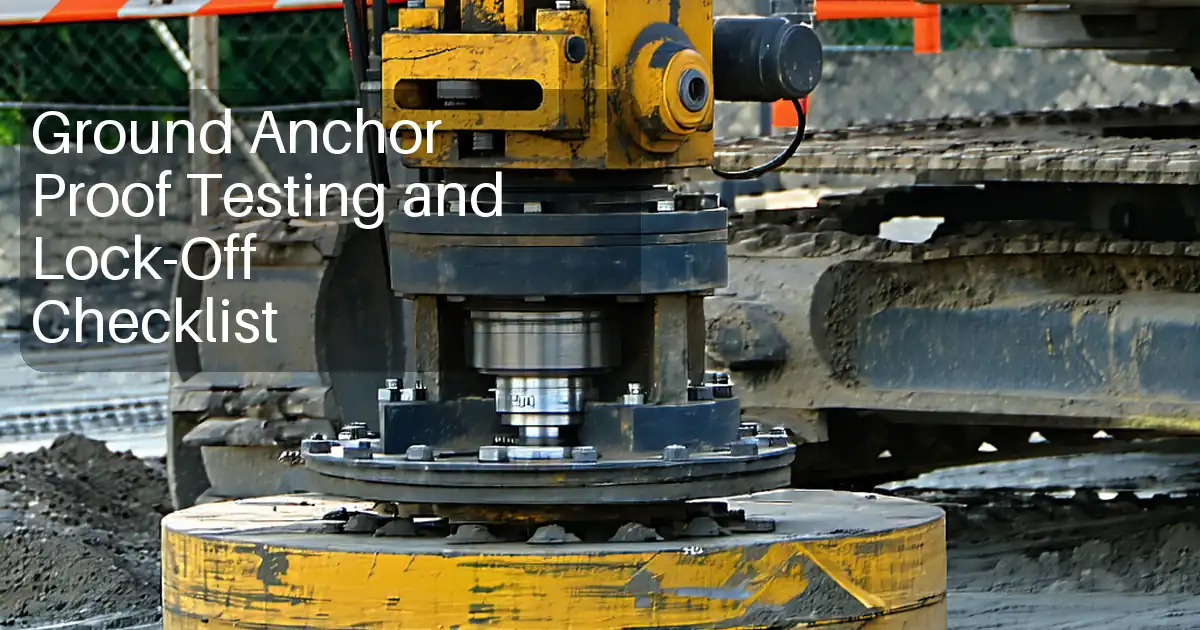
Install Ground Anchors Checklist: Lengths, Protection, Grouting
Definition: Install ground anchors with this field-ready checklist verifying tendon length, corrosion protection, bond/free lengths, and grouting quality for construction contractors, inspectors, and site engineers.
- Confirm tendon length and bond/free lengths match approved design.
- Verify double corrosion protection integrity on permanent anchor tendons.
- Control grout mix, pressures, volumes, and returns for sound encapsulation.
- Interactive, commentable checklist with export and QR code traceability.
Install ground anchors correctly by verifying tendon length, corrosion protection, bond and free lengths, and grouting. This checklist supports ground anchor installation teams, field inspectors, and site engineers by focusing on tendon assembly verification, debonded free length, bonded length, and grout placement controls. It excludes proof tests and stressing results, keeping the scope tight to installation and documentation quality. You’ll confirm sheath continuity, grease fill where specified, centralizers for cover, trumpet and bearing details, and borehole depth versus design. Grouting controls include approved mix design, mixing time, water–cement ratio, pressure, temperature, bleed limits, placement via tremie, and collar returns. Acceptance cues and photo evidence requirements are embedded to prevent hidden defects, reduce corrosion risk, and ensure load transfer where designed. Use this interactive, commentable tool to standardize records across shifts and subcontractors. Tick items as you go, add comments and photos, and export to PDF/Excel with a QR for traceable sign-off.
- Ensure each anchor tendon matches the approved total length, with free and bond lengths marked and verified in situ. Document measurements with calibrated tapes and photos, preventing under-length tendons that reduce elongation or insufficient bond that compromises load transfer.
- Achieve durable service life by confirming corrosion protection systems before installation: intact sheathing, sealed trumpets, correct grease fill (where specified), and continuous double corrosion protection for permanent anchors. Evidence includes leak checks, batch certificates, and close-up photos of critical interfaces.
- Grout correctly the first time by controlling water–cement ratio, mixing time, temperature, placement pressure, and continuous returns at the collar. Record volumes and pressure trends to confirm full encapsulation and promptly top-up if settlement occurs, eliminating voids and weak interfaces.
- Interactive online checklist with tick, comment, and export features secured by QR code.
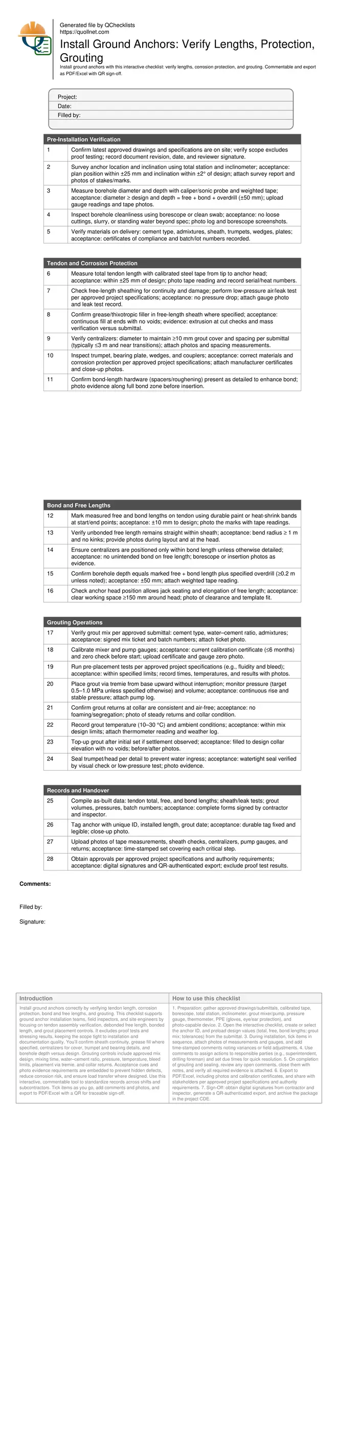
Pre-Installation Verification
Tendon and Corrosion Protection
Bond and Free Lengths
Grouting Operations
Records and Handover
Why tendon length and corrosion protection control are critical
Ground anchors rely on precise free and bond lengths to achieve design elongation and predictable load transfer. Short free length can cause overstressing, while insufficient bond length reduces capacity and increases movement. Before installation, verify the total tendon length and mark free/bond zones so the crew can visually align with the drawings. Corrosion protection is equally vital, especially for permanent anchors: intact sheathing, sealed trumpets, and correct grease fill (where specified) prevent moisture ingress and corrosion pitting. Centralizers maintain grout cover, keeping steel away from soil and ensuring uniform grout encapsulation. Use calibrated tapes, borescope checks for cleanliness, and leak tests on sheathing where specified. Capture photos of tape readings at the tendon tip and head, sheath condition, and centralizer locations. These steps materially reduce rework and extend service life by protecting the tendon from aggressive environments and ensuring the anchor behaves as designed.
- Mark and photo-verify free and bond length limits.
- Use calibrated measurements and keep certificates on file.
- Seal trumpets and verify sheath continuity.
- Maintain grout cover with correctly sized centralizers.
Getting bond and free lengths right in the borehole
After drilling, confirm the borehole depth equals the sum of free and bond lengths plus the specified overdrill. Measure diameter to ensure it meets or exceeds design so the centralizers can perform. Insert the tendon carefully to avoid kinking the unbonded free length; maintain the minimum bend radius and avoid unintended bonding by keeping the sheathing intact through the free zone. Place spacers or roughening elements only in the bond length as detailed. Verify head position and clear working space so stressing equipment can seat later without modification. Use borescopes or insertion photos to document the tendon at key intervals, showing centralizer spacing and the transition between free and bond sections. These checks help avoid hidden friction losses, ensure predictable elongation, and create a clear record for future maintenance or investigation if movement is observed after construction.
- Confirm borehole depth and diameter with records.
- Prevent unintended bonding along free length.
- Provide adequate head clearance for equipment.
- Photo-document insertion and transitions.
Grouting quality: mix control, placement, and verification
Quality grouting locks the bond length into the surrounding ground and shields steel from corrosion. Start with an approved mix design and confirm water–cement ratio, mixing time, and allowable admixtures. Calibrate gauges and verify fluidity/bleed limits per approved project specifications. Place grout from the base upward via tremie in a continuous operation, monitoring pressure and grout take to identify voids or obstructions. Look for steady, air-free returns at the collar and be ready to top-up after initial set if settlement occurs. Record temperature of grout and ambient conditions, as they affect set and viscosity. Finally, seal the trumpet/head to prevent water ingress. Comprehensive logs—pressures, volumes, batch numbers—and time-stamped photos of gauges and returns will prove full encapsulation and reduce disputes during closeout.
- Verify mix design and batch tickets.
- Monitor pressure and grout take continuously.
- Ensure air-free collar returns and top-up if needed.
- Seal trumpet and archive calibrated data.
How to Use This Ground Anchor Installation Checklist
- Preparation: gather approved drawings/submittals, calibrated tape, borescope, total station, inclinometer, grout mixer/pump, pressure gauge, thermometer, PPE (gloves, eye/ear protection), and photo-capable device.
- Open the interactive checklist, create or select the anchor ID, and preload design values (total, free, bond lengths; grout mix; tolerances) from the submittal.
- During installation, tick items in sequence, attach photos of measurements and gauges, and add time-stamped comments noting variances or field adjustments.
- Use comments to assign actions to responsible parties (e.g., superintendent, drilling foreman) and set due times for quick resolution.
- On completion of grouting and sealing, review any open comments, close them with notes, and verify all required evidence is attached.
- Export to PDF/Excel, including photos and calibration certificates, and share with stakeholders per approved project specifications and authority requirements.
- Sign-Off: obtain digital signatures from contractor and inspector, generate a QR-authenticated export, and archive the package in the project CDE.
Call to Action
- Start Checklist Tick off tasks, leave comments on items or the whole form, and export your completed report to PDF or Excel—with a built-in QR code for authenticity.
- Download Excel - Ground Anchor Installation Verification (No Proof Testing)
- Download PDF - Ground Anchor Installation Verification (No Proof Testing)
- View Image - Ground Anchor Installation Verification (No Proof Testing)
Cite & Embed
“Ground Anchor Installation Verification (No Proof Testing) by Quollnet”
with a link to
this source page.

FAQ
Question: What is the difference between free length and bond length on a ground anchor?
Question: How do I measure and verify the tendon length accurately on site?
Question: What grout controls matter most during anchor installation?
Question: Which corrosion protection features should be documented for permanent anchors?
Question: What records are required at handover if proof tests are excluded?
Related Articles
Broader reading and guidance connected to this checklist topic.


Tender Bid Bond Guide: Definitions, Best Practices & Free Templates


Is It Important To Customize Your Qr Code And How To Do It?
Related Checklists
Keep the workflow moving with nearby templates chosen from similar checklist content.