Method Statement – Prefabricated Vertical Drains (PVD/Wick Drains) Installation, Surcharge Preloading, and Settlement Monitoring – Method Statement
AI-assisted method statement with matching ITP, PDF download, and Excel export.
More than a static template
Unlike a downloadable Word or PDF template, this method statement is an AI-assisted editable starting point connected directly to a matching Inspection and Test Plan. Every section is structured, project-adaptable, and ready to export.
- AI-assisted drafting — Customize every section with AI for your specific project scope.
- Linked ITP — A matching inspection and test plan is generated alongside the method statement.
- Multiple export formats — Download as a formatted PDF or editable Excel spreadsheet.
- Editable starting point, not a final document — Review, verify, and adjust all content against your project requirements before use.
Static template vs. Quollnet workflow
| Feature | Static template | Quollnet |
|---|---|---|
| Project-specific content | Manual fill-in required | AI-assisted customization |
| Linked ITP | Separate document, no link | Matching ITP included |
| Export formats | Usually PDF only | PDF and Excel |
| Structured sections | Free-form layout | 13 standardized sections |
| Saved to your account | Local file only | Cloud-saved, reusable |
| Content accuracy | You verify everything | AI-assisted, you still verify |
| Cost | Often free but time-intensive | Free to customize and download |
What you can customize
When you save this method statement to your account, every section becomes editable. The following 13 sections are included:
- Scope — Defines the activity and its boundaries.
- References — Standards, specifications, and drawings.
- Responsibilities — Roles and accountabilities.
- Resources — Labour, plant, and equipment summary.
- Materials — Materials and compliance requirements.
- Equipment — Tools and equipment details.
- Prerequisites — Hold points and pre-conditions.
- Method sequence — Step-by-step construction sequence.
- Safety controls — HSE risk controls and PPE.
- Environmental controls — Environmental mitigation measures.
- QA/QC — Quality inspection and test requirements.
- ITP — Inspection and Test Plan table (has its own page).
- Attachments — Referenced drawings and documentation.
Why this method statement is used
This method statement is used to define and communicate the approved procedure for carrying out method statement – prefabricated vertical drains (pvd/wick drains) installation, surcharge preloading, and settlement monitoring on site. It ensures the work is planned in advance, the correct resources and controls are in place, and all personnel understand responsibilities, sequence, quality requirements, and safety controls before work begins. It aligns site execution with the documented scope and acceptance expectations.
Who uses this method statement
This method statement is used by contractors, site supervisors, project engineers, QA/QC engineers, HSE officers, consultants, and client representatives. It serves as a shared reference for planning, execution, supervision, inspection, and approval of the activity on site.
When it is prepared and submitted
The method statement is prepared before the work activity starts and submitted as part of the pre-construction documentation package for review and approval.
Who reviews or approves it
The method statement is usually submitted to the client representative, consultant, resident engineer, or project management consultant for review and approval before the work commences.
Important approval note
This method statement is an AI-assisted editable starting point, not a pre-approved document. Before use on any project, all content must be reviewed and approved by the relevant parties (superintendent, principal contractor, or client representative) in accordance with your contract and project quality plan.
For example: if your specification requires a departure from a referenced standard, that departure must be documented and approved separately — this method statement will not capture that automatically. Always verify against your applicable drawings, specifications, and regulatory requirements.
Method statement content
Scope
Purpose
Provide a complete method for supply, installation, and testing of prefabricated vertical drains (PVD/wick drains) to accelerate primary consolidation of soft cohesive soils, followed by staged surcharge preloading and settlement monitoring using settlement plates (and associated instruments where specified).
Work Included
- Submittals and approvals for PVD materials, rig parameters, working platform, and instrumentation.
- Establishment of grid layout and positioning control for drains using survey/DGPS.
- Trial installation to confirm rig settings, penetration rates, anchor performance, and termination criteria.
- Production installation of PVD using stitcher mandrel rig, including anchoring, retraction, splicing control, top termination, and as-built logging.
- Placement of drainage blanket/collection layer and staged surcharge preloading.
- Installation and monitoring of settlement plates (and piezometers if specified).
- QA/QC testing, verification, and as-built documentation.
- HSE and environmental controls specific to PVD and surcharge works.
Exclusions
- Ground treatment other than PVD and surcharge (e.g., stone columns, vacuum consolidation) unless noted.
- Permanent drainage systems beyond surcharge period unless specified.
Key Objectives
- Achieve target degree of consolidation (e.g., ≥90% consolidation) and predicted settlements within the preload period [Verify per project specifications].
- Maintain ground stability during installation and preload through staged fill placement and monitoring.
- Deliver traceable as-built records for every drain (ID, coordinates, depth, spool/batch).
References
| Document Type | Reference / Number | Revision | Notes |
|---|---|---|---|
| Standard | ASTM D7001 | ||
| Standard | EN ISO 12958-1 / ASTM D4716 | ||
| Standard | EN ISO 11058 | ||
| Standard | EN ISO 12956 | ||
| Standard | EN ISO 10319 / ASTM D4595 | ||
| Standard | ASTM D4491 / ASTM D4632 | ||
| Standard | BS EN 1997-1 | ||
| Standard | BS 6031 | ||
| Guide | BRE BR470 | ||
| Guide | FHWA NHI-13-013 | ||
| Standard | ISO 9001 |
Responsibilities
| Role | Responsibility | Name / Party |
|---|---|---|
| PM | Contractor | Contractor |
| CM | Contractor | Contractor |
| GE | Contractor/Designer | Contractor |
| SE | Contractor | Contractor |
| HSE | Contractor | Contractor |
| QC | Contractor | Contractor |
| SURV | Contractor | Contractor |
| OP | Contractor | Contractor |
| Lab | Independent | Third Party |
| ER | Client/Engineer | Client/Engineer |
Resources (Personnel)
| Resource Type | Description | Quantity | Remarks |
|---|---|---|---|
| Labor | Rig operator, assistant, rigger/banksman, QC tech, survey support | 5–7 | |
| Labor | Dozer operator, dump truck drivers, grader/roller operator, spotter | 6–10 | |
| Labor | Technician to install settlement plates, read instruments, compile data | 2–3 |
Materials
| Material | Specification / Grade | Quantity | Remarks |
|---|---|---|---|
| PP | |||
| PP | |||
| Steel | |||
| Sand | |||
| Granular/Engineered fill | |||
| Steel/GI |
Equipment
| Equipment | Capacity / Type | Quantity | Inspection Required |
|---|---|---|---|
| Stitcher Rig | Push force 50–120 kN; vib head 30–50 Hz [Verify] | 1–2 | Yes |
| Mandrel | 1 per rig | Yes | |
| Survey | 1 set | Yes | |
| Survey/Monitoring | As required | Yes | |
| Dozer/Trucks | As required | Yes | |
| N/A | Yes |
Prerequisites
- Approved method statement, ITP, risk assessment, emergency plan, and permits [Verify per project HSE plan and local regulations].
- Approved PVD material submittals with manufacturer certificates (ISO 9001), test reports for core transmissivity, sleeve permittivity/O90, tensile properties.
- Utility clearance: permit-to-dig, review of utility plans; where required, geophysical scanning in working areas.
- Certified working platform design and installation per BRE BR470; daily inspection log.
- Survey control network established and verified; DGPS/Total Station calibrated.
- Trial installation area agreed; hold/witness by Engineer.
- Baseline monitoring points established and initial readings taken (settlement plates/piezometers if pre-installed).
- Weather constraints reviewed (avoid installation during lightning, extreme wind for rig stability; manage surface water).
- Crew competency: rig operator certification; task-specific training/toolbox talks.
- Laboratory engaged for conformance testing; sampling plan agreed.
- Surcharge fill source approved; haul routes and traffic management plan in place.
Method Sequence
| Step | Activity | Description | Responsibility | Inspection / Hold Point |
|---|---|---|---|---|
| 1 | Site establishment and access | Mobilize rig and plant; install signage, barriers, haul routes, and safe working platform per approved design. | Construction Manager | HSE and platform inspection |
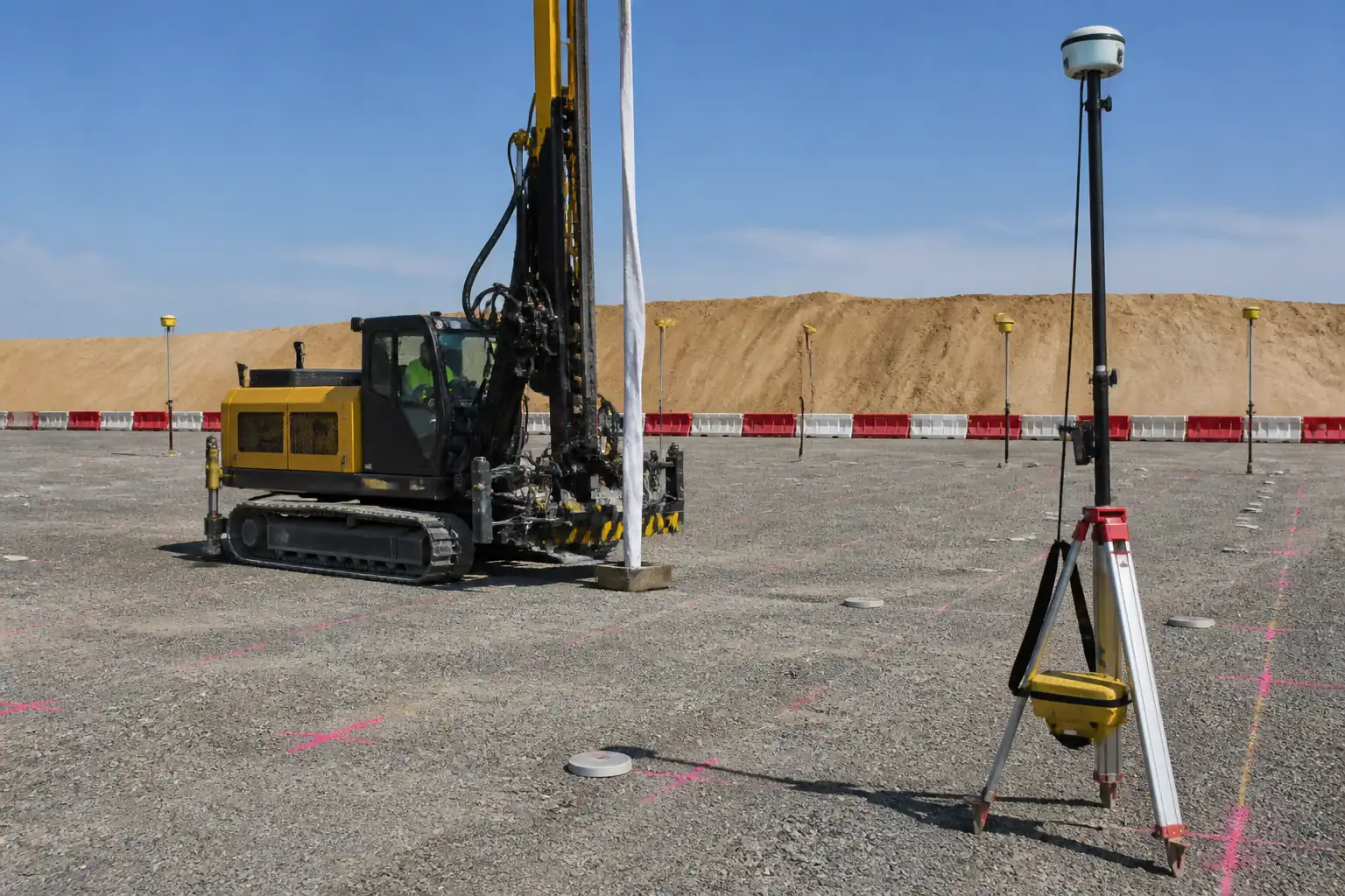
| 2 | Grid set-out | Stake PVD locations using DGPS/Total Station; upload digital grid to rig guidance system if available. | Surveyor | Survey QA |
| 3 | Trial installations | Install 10–20 trial drains to validate penetration rate, verticality, depth termination, anchor performance, and retraction parameters. | Geotechnical Engineer / QC | Hold point – Engineer witness |
| 4 | Material control | Inspect coils/spools for labels, batch numbers; sample per lot for third-party tests; protect from UV and mud. | QC Engineer | Receiving inspection |
| 5 | Rig setup and mandrel preparation | Fit mandrel and anchor shoe; thread drain; set vibrator frequency and static push; verify plumb mast and auto-vertical controls. | Rig Operator | Pre-start check |
| 6 | Insertion/penetration | Position mandrel over marked point; apply static push with optional vibration; maintain steady rate; record depth profile. | Rig Operator / QC | In-process monitoring |
| 7 | Depth termination | Terminate at design elevation referenced to site benchmark. If obstruction encountered above design depth, attempt offset installs. | Geotechnical Engineer / Site Engineer | Depth verification |
| 8 | Anchoring and mandrel withdrawal | Anchor drain with disposable plate; retract mandrel smoothly keeping slight back-tension on drain; avoid dragging soil into sleeve. | Rig Operator / QC | In-process check |
| 9 | Splicing control (if spool change) | Perform approved splice (heat-weld/mechanical) above ground; reinforce with sleeve overlap as per supplier; mark splice location. | Rig Crew / QC | Witness |
| 10 | Top termination and identification | Cut drain to extend 100–200 mm above drainage blanket interface (or as designed); tag with drain ID, depth, spool/batch; protect until blanket placement. | Rig Crew / QC | Visual |
| 11 | As-built logging | Capture each drain’s coordinates (x,y), depth, date/time, rig ID, spool/batch, remarks; export daily CSV/shape files for review. | Site Engineer / Survey | Desk review |
| 12 | Drainage blanket placement | Place clean sand blanket to designed thickness; trim PVD flush at top of blanket; install surface collection drains if specified. | Construction Manager | QC inspection |
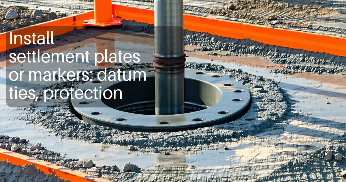
| 13 | Settlement plate installation | Set base plate on leveled surface atop blanket or subgrade (as designed); erect riser vertically; protect with bollards; survey initial RL. | Instrumentation Team / Survey | Witness point |
| 14 | Staged surcharge preloading | Place surcharge in controlled lifts; maintain stability; install/check toe/drainage measures; monitor settlement and pore pressure (if provided). | Geotechnical Engineer / CM | Hold point at each stage |
| 15 | Monitoring and decision to unload | Read settlement plates daily during active fill, then 2–3 times/week; evaluate degree of consolidation (Asaoka/Time–Settlement); confirm targets. | Geotechnical Engineer | Data review |
| 16 | Demobilization and reinstatement | Remove surcharge (if temporary), trim to formation, remove protections; deliver final as-builts and monitoring dossier. | Construction Manager | Final inspection |
Health, Safety and Environment – Task-Specific Controls
Key Hazards and Controls
- Hazard: Underground utility strike during mandrel penetration.
- Likely consequence: Electrocution, explosion, service outage.
- Engineering/procedural control: Permit-to-dig; utility plans review; scanning where uncertainty exists; exclusion zones over known services; trial holes if required.
- Required PPE: Dielectric gloves (for spotters near electrical risk), safety boots, helmet, high-vis, eye protection.
- Collective preventive measure: Physical barriers and marking paint over service routes; no-go zones loaded onto DGPS.
-
Inspection/permit/supervision: Permit-to-dig signed; supervisor verification before each shift; [Verify per project HSE plan and local regulations].
-
Hazard: Rig instability/overturning on soft ground.
- Likely consequence: Crushing, equipment damage, spill.
- Control: Engineered working platform per BRE BR470; daily visual checks; weather limits (wind); use of rig mats where needed; maintain safe slew radius.
- PPE: Helmet, steel-toe boots, high-vis, gloves.
- Collective: Edge protection, level platform, banksman control.
-
Inspection/permit/supervision: Platform certificate; pre-start checks; lifting plan if crane-assisted components.
-
Hazard: Mandrel pinch/crush during threading and retraction.
- Consequence: Hand injuries, lacerations.
- Control: Use threading guides; lock-out during threading; no hands near mandrel path; trained personnel only.
- PPE: Cut-resistant gloves, eye protection.
- Collective: Guarding and interlocks where available.
-
Inspection/permit/supervision: Toolbox talk; supervisor sign-off.
-
Hazard: Working near overhead power lines (OPL) during mast raising.
- Consequence: Electrocution, arcing.
- Control: OPL survey; maintain statutory clearances; fit height restrictors; use spotter.
- PPE: Standard site PPE; arc-rated where required.
- Collective: Physical goalposts and signage.
-
Inspection/permit/supervision: Permit to work near OPL; daily briefing.
-
Hazard: Ground failure during surcharge placement (bearing/slip).
- Consequence: Plant rollover, rapid settlement, lateral spread.
- Control: Staged fill; FoS checks; keep fill rate within limits; maintain berms and toe drains; restrict plant to specified zones.
- PPE: Standard site PPE.
- Collective: Traffic management and exclusion zones; emergency egress planned.
-
Inspection/permit/supervision: Hold point before each lift; geotechnical review of monitoring data.
-
Hazard: Exposure to noise and vibration.
- Consequence: Hearing damage, nuisance.
- Control: Select low-vibration settings; maintain equipment; schedule noisy operations daytime.
- PPE: Hearing protection per noise assessment.
- Collective: Barriers/signage for public interfaces.
-
Inspection/permit/supervision: Noise monitoring if required by permit.
-
Hazard: Manual handling of spools and settlement plate components.
- Consequence: Strain injuries.
- Control: Mechanical aids; team lifts; proper storage heights.
- PPE: Gloves, safety boots.
- Collective: Use forklifts/pallet jacks.
-
Inspection/permit/supervision: Manual handling training.
-
Hazard: Diesel/hydraulic spills from rig and plant.
- Consequence: Ground/water contamination, slip hazard.
- Control: Drip trays under parked plant; biodegradable oils where feasible; spill kits at rigs; refuel in designated area.
- PPE: Nitrile gloves, eye protection when handling oils.
- Collective: Bunded refueling area.
-
Inspection/permit/supervision: Environmental permit and inspections.
-
Hazard: Working around open water/soft mud (if present).
- Consequence: Drowning, entrapment.
- Control: Rescue plan; avoid lone working; defined walkways/temporary mats.
- PPE: Life jacket where required.
- Collective: Lifebuoys and reach poles.
- Inspection/permit/supervision: Permit and standby rescue.
Environmental Controls
- Surface water and sediment control: Install silt fences, straw bales, or settlement ponds around surcharge area; maintain positive drainage; inspect before/after rainfall.
- Noise and vibration: Use low-vibration settings; limit hours to permitted windows; maintain silencers; monitor if near receptors [Verify per local permit].
- Air quality/dust: Wet down haul roads; cover trucks; enforce speed limits; wheel wash at egress points.
- Waste management: Segregate PP offcuts and packaging; recycle where facilities exist; dispose via licensed waste contractor; maintain waste transfer records.
- Hydrocarbon management: Refuel in bunded areas; fit drip trays; store fuels/chemicals in compliant containers; keep spill kits accessible; train crews.
- Water quality: Prevent slurry/mud from entering watercourses; use sumps and pump to treatment if necessary.
- Ecology: Exclusion zones for sensitive habitats; pre-works checks if required by permits.
- Cultural heritage: Cease work and notify if unexpected finds occur [Verify per project requirements].
- Environmental monitoring: Record inspections weekly and after significant rain; rectify nonconformities promptly.
Quality Assurance / Quality Control
Material QA/QC
- Review manufacturer Certificates of Compliance for each batch, including test reports: core transmissivity (EN ISO 12958-1 / ASTM D4716), sleeve permittivity (EN ISO 11058)/O90 (EN ISO 12956), tensile (EN ISO 10319 or ASTM D4595/D4632). Sampling frequency: minimum 1 set per batch or per 50,000 m of drain installed [Verify per spec].
- Visual inspection: damage-free spools, correct labeling, width within ±5 mm, no delamination or contamination.
Installation QA/QC
- Location tolerance: installed drain head within ±0.15 m of design coordinates [Verify].
- Depth tolerance: final tip elevation within -0.30/+0.10 m of design [Verify].
- Verticality: mandrel ≤1:50 deviation [Verify].
- Anchor performance: proof pull ≥0.5 kN for 10 s (random 1 per 100 drains) [Verify].
- Splices: tensile capacity ≥50% of drain tensile; record all splice locations.
- Retraction: controlled speed with continuous back-tension; no evidence of pull-out.
- Top termination: projection as designed; trimmed flush to top of drainage blanket.
Records and As-Builts
- 100% drain IDs with x/y coordinates, depth, date/time, rig ID, spool/batch/lot, splice locations, refusal notes.
- Daily production report and DGPS export (CSV/shapefile) and PDFs of as-built plans.
- ITP Inspection/Test Records (ITRs) signed by QC and Engineer where required.
Nonconformance and Corrective Action
- Triggers: out-of-tolerance position/depth, drain damage, repeated refusal.
- Actions: relocate drain by 0.5 m increments (≤3 attempts), add supplementary drains if required by Engineer, repair/replace damaged drains, update grid/as-builts.
Monitoring QA/QC
- Settlement plates: initial and subsequent readings to ±2 mm; frequency: daily during active filling, 2–3/week during waiting periods; weekly after stabilization [Verify].
- Acceptance for de-surcharging: evidence that degree of consolidation U≥90–95% and trends stable; pore pressures (if used) near equilibrium; confirmation memo by Geotechnical Engineer and Engineer approval.
Attachments
- PVD manufacturer datasheets and certificates (core and sleeve) with accredited test reports.
- Stitcher rig technical data: push/vibration capacities, mandrel dimensions, calibration records, maintenance logs.
- Working platform design and certificate; inspection and maintenance plan.
- Grid layout drawings and setting-out data; coordinate files.
- Sample ITR/checklists for PVD installation, splice/anchor checks, depth/location logs.
- Settlement plate standard detail and monitoring forms.
- Surcharge preloading staging plan and stability calculation summary.
- HSE risk assessment, method-specific permits, emergency response plan.
- Environmental management plan and spill response procedure.
- Trial drain report including optimized parameters.
- As-built templates (CSV/shapefile schema) and example daily report.
This content is a read-only public reference. Download or customize to get an editable version.
ITP preview
The first inspection activities from the linked ITP for Method Statement – Prefabricated Vertical Drains (PVD/Wick Drains) Installation, Surcharge Preloading, and Settlement Monitoring:
| Activity | Inspection / Test | Acceptance Criteria | Responsibility | Record |
|---|---|---|---|---|
| Material approvals – PVD core and sleeve | Review CoC and third-party tests (transmissivity, permittivity, O90, tensile) | Conform to approved properties and batches identified | Contractor QC / Engineer | Material approval; test certificates |
| Working platform certification | Visual/CBR/plate load (if required) | Meets design and safe bearing for rig | Contractor / Temporary Works Designer / Engineer | Platform certificate; inspection sheet |
| Survey control and grid set-out | Calibration; independent check shots | Positional accuracy within project tolerance | Surveyor / QC | Set-out report |
Showing 3 of 12 inspection activities. View full ITP →
Related Inspection and Test Plan
An Inspection and Test Plan (ITP) is available for Method Statement – Prefabricated Vertical Drains (PVD/Wick Drains) Installation, Surcharge Preloading, and Settlement Monitoring. The ITP defines the inspection activities, acceptance criteria, hold and witness points, responsible parties, and records required to verify the work described in this method statement.
View the Method Statement – Prefabricated Vertical Drains (PVD/Wick Drains) Installation, Surcharge Preloading, and Settlement Monitoring ITP →Frequently asked questions
Continue with related Quollnet resources connected to this method statement.