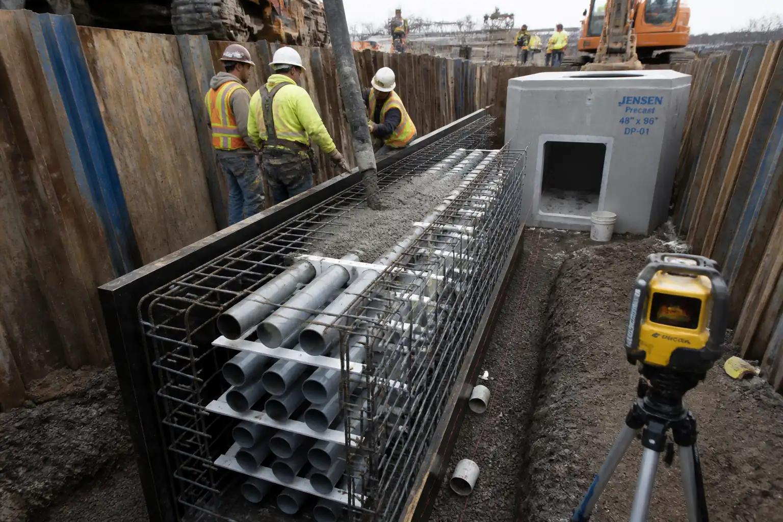
Inspection and Test Plan for Method Statement for Installation of Concrete‑Encased Duct Banks (LV, HV, Telecom & Fibre Optic) with Draw Pits
AI-assisted inspection and test plan connected to a method statement, with PDF and Excel export.
More than a static template
Unlike a downloadable Word or PDF template, this ITP is an AI-assisted editable starting point directly connected to its method statement. Every inspection activity, hold point, and acceptance criterion is structured and ready to adapt to your project.
- AI-assisted customization — Tailor inspection activities and acceptance criteria to your specific project scope.
- Linked method statement — This ITP is connected to the corresponding method statement describing the work sequence.
- Multiple export formats — Download as a formatted PDF or editable Excel spreadsheet.
- Editable starting point, not a final document — Review and verify all content against your project specifications and standards before use.
What you can customize
When you save this ITP to your account, every inspection row becomes editable. You can add, remove, or modify:
- Inspection activity — Description of what is being inspected.
- Inspection type — Hold point (H), Witness point (W), Review (R), or Monitor (M).
- Responsibility — Contractor, subcontractor, engineer, or client.
- Frequency — How often the inspection occurs.
- Acceptance criteria — Referenced standard or specification requirement.
- Records — Forms, test reports, or checklists required as evidence.
Why this ITP is used
To control and evidence quality and compliance at critical stages of duct bank construction.
Who uses this inspection and test plan
Contractor’s site/QA teams, third‑party labs, and the Engineer/Client for surveillance and acceptance.
When this ITP is prepared and submitted
From survey and excavation through concrete encasement, mandrel testing, pit works, to backfilling and final handover.
Who receives or approves this ITP
Engineer/Client Representative for approval and witnessing.
Inspection scope
Verification of materials, geometry, concrete quality, pit installation, mandrel testing, and backfill compaction across the full construction sequence.
Typical hold, witness, and review points
Pre‑pour checks of ducts/spacers/rebar (Hold), draw pit base/walls (Hold/Witness), and pre‑backfill after mandrel testing (Hold).
Typical inspection records
Inspection requests, concrete test reports, mandrel logs, continuity sheets, density tests, photos, and as‑built surveys.
Important approval note
This ITP is an AI-assisted editable starting point, not a pre-approved document. Before use on any project, all inspection activities, hold points, and acceptance criteria must be reviewed and approved by the relevant parties (superintendent, principal contractor, or client representative) in accordance with your contract and project quality plan.
Always verify acceptance criteria against your applicable drawings, specifications, and regulatory requirements. Hold points must be confirmed with the relevant authority before work proceeds past that point.
Inspection and test plan
| Activity | Inspection / Test | Acceptance Criteria | Responsibility | Record |
|---|---|---|---|---|
| Setting out and survey control | Check benchmarks; verify line/level | Within tolerances: line ±20 mm; level ±5–10 mm [Verify] | Surveyor / QA/QC | Setting‑out record/IR |
| Utility detection and trial pits | GPR/EML and hand‑dig verification | All crossings proven; no mechanical excavation within 1 m until confirmed clear | Site Engineer / HSE | Trial pit report; photos |
| Trench excavation, shoring, and bedding | Visual; level checks | Width/depth per IFC; bedding thickness/levels within ±10 mm | QA/QC / Engineer | IR; checklist |
| Ducts, spacers, restraints, reinforcement (Hold Point) | Visual, measurement of separation/cover | Separation/cover as per IFC; restraints ≤1.5 m; rebar per design | QA/QC + Engineer | IR (Hold) with photos |
| Concrete pre‑pour (Hold Point) | IR review; cleanliness; end caps; levels | Ducts clean/dry; alignment ok; checklists complete | QA/QC + Engineer | IR (Hold) |
| Concrete supply and placement | Slump, temperature, cylinders; placement observation | Results within approved limits; no duct displacement | QA/QC / Lab | Batch tickets; test reports |
| Curing inspection | Visual; curing duration | Curing maintained per spec (≥7 days or as approved) | Site Engineer / QA | Site diary |
| Draw pit base and wall installation (Hold/Witness) | Dimensions, levels, water‑tight joints, pulling eyes | Within ±5 mm; joints sealed; hardware installed | QA/QC / Engineer | IR; photos |
| Mandrel and swab test; roping; tracer wire continuity | Mandrel 80–90% ID; continuity meter | 100% ducts pass; continuity verified end‑to‑end | Electrical Supervisor / QA/QC | Mandrel log; continuity sheet |
| Pre‑backfill inspection (Hold Point) | Visual; check warning tape depth; confirm tests complete | All inspections passed; records available; site clean | QA/QC + Engineer | IR (Hold) |
| Backfill and compaction testing | FDT per lot/lift | ≥95% MDD (general) or ≥98% under pavements [Verify] | QA/QC / Lab | FDT reports; IR |
| Final inspection and as‑built | Survey check; visual of reinstatement | As‑built within tolerance; reinstatement per authority standard | Engineer/Client + Contractor | Signed IR; as‑built drawings |
This table is a read-only public reference. Download the PDF or Excel version, or customize this ITP to edit it for your project.
Frequently asked questions
Related method statement
This Inspection and Test Plan is associated with the Method Statement for Installation of Concrete‑Encased Duct Banks (LV, HV, Telecom & Fibre Optic) with Draw Pits method statement, which describes the step-by-step construction sequence, resources, materials, equipment, safety controls, and environmental controls for this activity.
View the Method Statement for Installation of Concrete‑Encased Duct Banks (LV, HV, Telecom & Fibre Optic) with Draw Pits method statement →