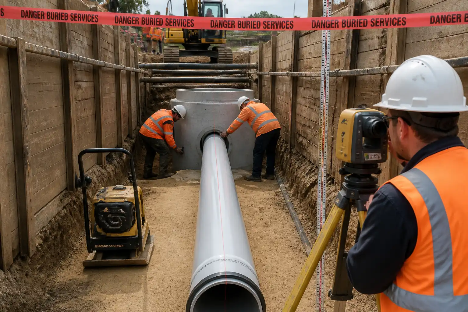
Method Statement for Installation of Concrete‑Encased Duct Banks (LV, HV, Telecom & Fibre Optic) with Draw Pits – Method Statement
AI-assisted method statement with matching ITP, PDF download, and Excel export.
More than a static template
Unlike a downloadable Word or PDF template, this method statement is an AI-assisted editable starting point connected directly to a matching Inspection and Test Plan. Every section is structured, project-adaptable, and ready to export.
- AI-assisted drafting — Customize every section with AI for your specific project scope.
- Linked ITP — A matching inspection and test plan is generated alongside the method statement.
- Multiple export formats — Download as a formatted PDF or editable Excel spreadsheet.
- Editable starting point, not a final document — Review, verify, and adjust all content against your project requirements before use.
Static template vs. Quollnet workflow
| Feature | Static template | Quollnet |
|---|---|---|
| Project-specific content | Manual fill-in required | AI-assisted customization |
| Linked ITP | Separate document, no link | Matching ITP included |
| Export formats | Usually PDF only | PDF and Excel |
| Structured sections | Free-form layout | 13 standardized sections |
| Saved to your account | Local file only | Cloud-saved, reusable |
| Content accuracy | You verify everything | AI-assisted, you still verify |
| Cost | Often free but time-intensive | Free to customize and download |
What you can customize
When you save this method statement to your account, every section becomes editable. The following 13 sections are included:
- Scope — Defines the activity and its boundaries.
- References — Standards, specifications, and drawings.
- Responsibilities — Roles and accountabilities.
- Resources — Labour, plant, and equipment summary.
- Materials — Materials and compliance requirements.
- Equipment — Tools and equipment details.
- Prerequisites — Hold points and pre-conditions.
- Method sequence — Step-by-step construction sequence.
- Safety controls — HSE risk controls and PPE.
- Environmental controls — Environmental mitigation measures.
- QA/QC — Quality inspection and test requirements.
- ITP — Inspection and Test Plan table (has its own page).
- Attachments — Referenced drawings and documentation.
Why this method statement is used
This method statement is used to define and communicate the approved procedure for carrying out method statement for installation of concrete‑encased duct banks (lv, hv, telecom & fibre optic) with draw pits on site. It ensures the work is planned in advance, the correct resources and controls are in place, and all personnel understand responsibilities, sequence, quality requirements, and safety controls before work begins. It aligns site execution with the documented scope and acceptance expectations.
Who uses this method statement
This method statement is used by contractors, site supervisors, project engineers, QA/QC engineers, HSE officers, consultants, and client representatives. It serves as a shared reference for planning, execution, supervision, inspection, and approval of the activity on site.
When it is prepared and submitted
The method statement is prepared before the work activity starts and submitted as part of the pre-construction documentation package for review and approval.
Who reviews or approves it
The method statement is usually submitted to the client representative, consultant, resident engineer, or project management consultant for review and approval before the work commences.
Important approval note
This method statement is an AI-assisted editable starting point, not a pre-approved document. Before use on any project, all content must be reviewed and approved by the relevant parties (superintendent, principal contractor, or client representative) in accordance with your contract and project quality plan.
For example: if your specification requires a departure from a referenced standard, that departure must be documented and approved separately — this method statement will not capture that automatically. Always verify against your applicable drawings, specifications, and regulatory requirements.
Method statement content
Scope
Work Summary
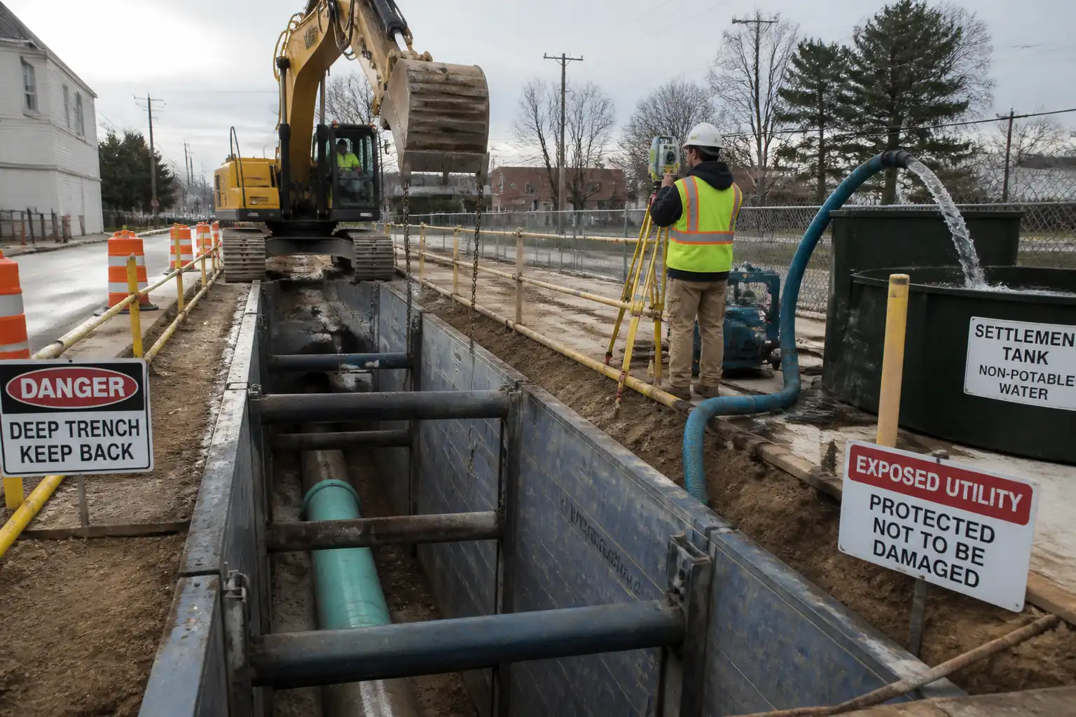
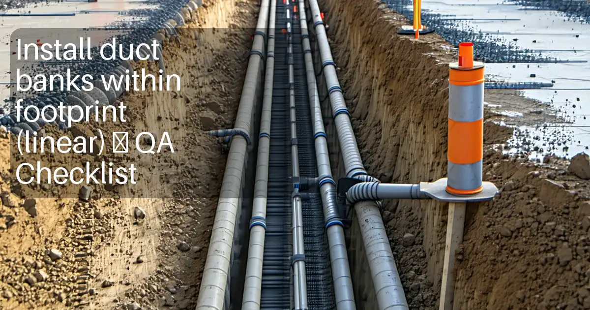
This method covers the end‑to‑end installation of concrete‑encased multi‑cell duct banks for LV, HV, telecom, and fibre optic systems, including:
- Setting out and utility detection
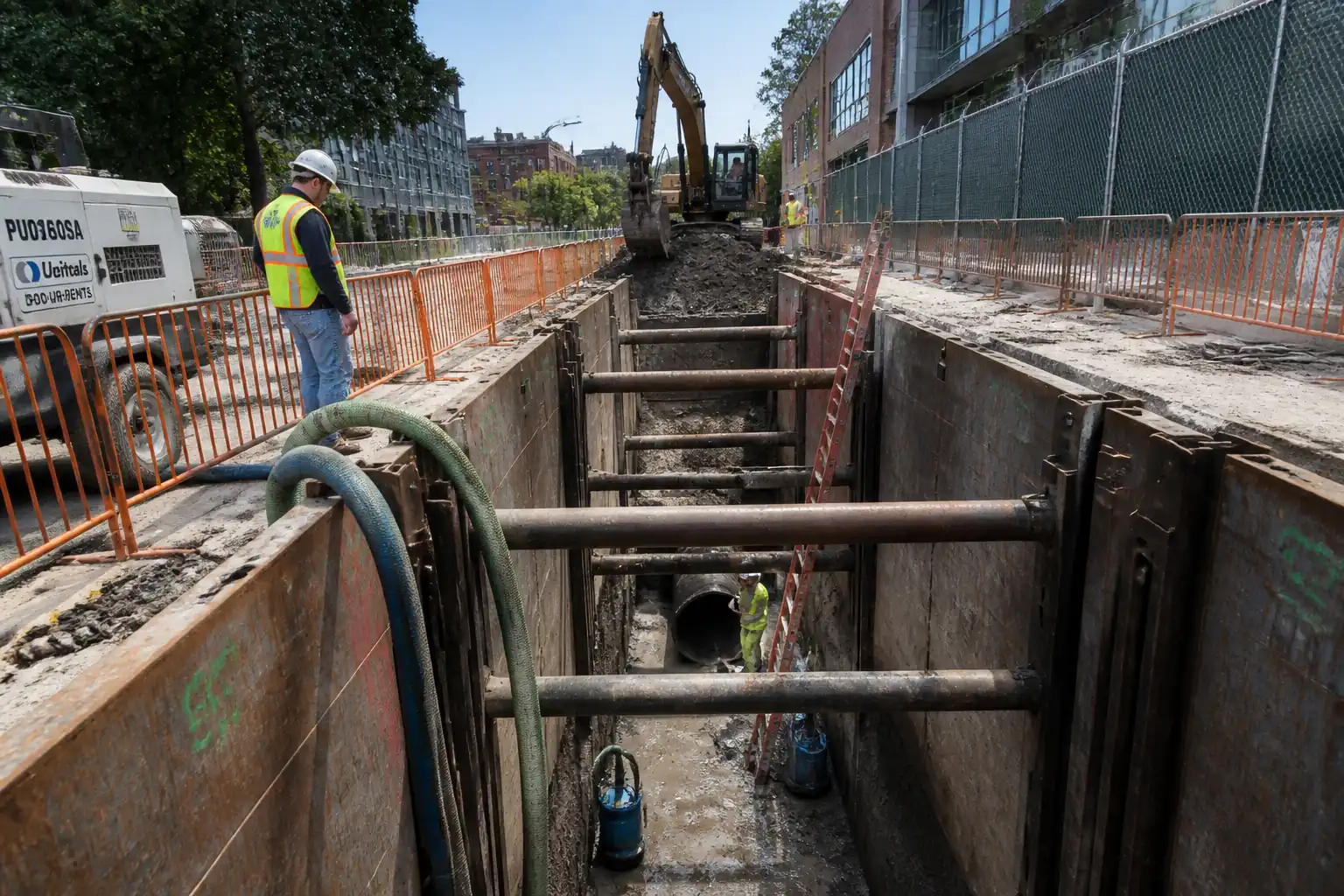
- Trenching, shoring, and dewatering (as required)
- Bedding preparation and spacer assembly
- Duct placement, alignment, gradient, joints, and sealing
- Reinforcement and formwork (if required by design)
- Concrete encasement placement, compaction, and curing
- Draw pit/handhole/manhole construction, duct terminators, and cable pulling eyes
- Mandrel and swab testing, roping, and tracer wire continuity
- Warning tape/marker installation, backfilling, compaction, and reinstatement
- Inspections, test sampling, and hold points prior to backfill and handover
Location
- As per IFC drawings and approved utility corridor alignment within .
Exclusions
- Cable pulling/termination and jointing not included unless stated.
- Cathodic protection and earthing grids beyond pit earthing are by others unless specified.
Objectives
- Deliver durable, geometrically compliant duct banks providing adequate mechanical protection, separation, and maintainability for LV/HV power and telecom/fibre cables.
- Achieve compliance with referenced standards and project specifications.
References
| Document Type | Reference / Number | Revision | Notes |
|---|---|---|---|
| ACI | ACI 301, ACI 304R, ACI 318 | ||
| ASTM/BS EN | ASTM C94; BS EN 206 | ||
| NEMA/ASTM | NEMA TC‑6 & 8; NEMA TC‑2; ASTM D1785; ASTM D3035 | ||
| ASTM | ASTM D2321 | ||
| NFPA/IEC | NFPA 70; IEC 60364 | ||
| TIA | TIA‑758; TIA‑606 | ||
| BS EN | BS EN 124 | ||
| BS EN/BS | BS EN 1917; BS 5911 | ||
| ASTM/BS | BS 4449; ASTM A615 | ||
| OSHA/BS/ISO | OSHA Subpart P; BS 6031; ISO 14688 |
Responsibilities
| Role | Responsibility | Name / Party |
|---|---|---|
| PM | Ensure method/ITP approvals; coordinate with stakeholders and utilities | Contractor |
| CM | Ensure competent supervision, coordination of civil and electrical teams | Contractor |
| Engineer | Checks and ITP sign‑offs for civil stages | Contractor |
| Supervisor | Assure compliance with NEC/TIA; coordinate with QA/QC | Contractor |
| QA/QC | Hold/witness coordination; material certificates; test requests | Contractor |
| HSE | PTW, excavation safety, lifting plans, emergency response | Contractor |
| Surveyor | Benchmark verification; as‑built survey | Contractor |
| Lab | Sampling, curing, and reporting | Approved Lab |
| Engineer | Review IRs; approve progression | Engineer/Client |
Resources
| Resource Type | Description | Quantity | Remarks |
|---|---|---|---|
| Manpower | Excavator operator, pipe layers, carpenters, steel fixers, concrete crew | 1 crew | |
| Manpower | Duct installation, spacer/mandrel/roping, labelling | 1 crew | |
| Manpower | 1 Surveyor + helper | 1 team |
Materials
| Material | Specification / Grade | Quantity | Remarks |
|---|---|---|---|
| Conduit | |||
| Spacers | |||
| Concrete | ASTM C94 / BS EN 206 | ||
| Rebar | |||
| Sand/Granular | |||
| Adhesives | |||
| Precast units | |||
| Markers | |||
| Accessories |
Equipment
| Equipment | Capacity / Type | Quantity | Inspection Required |
|---|---|---|---|
| 1–2 | |||
| As required | |||
| As required | |||
| 1 set | |||
| As required | |||
| 1 set | |||
| 1 set | |||
| As required |
Prerequisites
- Approved IFC drawings, shop drawings (duct bank cross‑sections, pit details), and this Method Statement/ITP.
- Material approvals: conduits, spacers, concrete mix design, reinforcing steel, draw pits/covers, warning tape, pull ropes, tracer wire.
- Permits: excavation permit, dewatering permit (if applicable), hot work (rebar cutting), traffic management permit, work in ROW easement approvals. [Verify per project HSE plan and local regulations]
- Utility clearance: recent GPR/EML survey; marked out; trial pits at crossings/critical points; utility owner confirmations.
- Calibrations: survey instruments, batching plant scales; concrete testing equipment.
- Pre‑start coordination/TBT: review hazards, sequence, hold points, and emergency procedures.
- Site controls ready: barricades, signage, trench shoring, access/egress, lighting (if night), spill kits, washout area, settlement tank for dewatering.
- Weather and groundwater: forecast checked; dewatering and groundwater inflow managed.
- Approved QA/QC forms: IRs, checklists, mandrel test log, concrete sampling plan.
- Contingency for unknown services: hand‑digging protocol and stop‑work escalation.
- Traffic management plan implemented and inspected where working adjacent to live traffic.
Method Sequence
| Step | Activity | Description | Responsibility | Inspection / Hold Point |
|---|---|---|---|---|
| 1 | Setting out and permits | Set primary control, mark duct bank alignment, invert levels and draw pit chainages; obtain permits and brief crews | Surveyor / Site Engineer | IR for setting out (surveillance) |
| 2 | Utility detection and trial holes | GPR/EML scan, mark services; hand‑dig trial pits at crossings; document depths/positions | HSE / Site Engineer | Hold point if conflicts discovered |
| 3 | Trench excavation and shoring | Excavate to design width/depth; install trench boxes/shoring or cut safe batter; maintain access/egress every 7.5–9 m | Foreman / HSE | Daily excavation inspection |
| 4 | Dewatering and ground stabilization (if required) | Install sumps/wellpoints; discharge through settlement tank; maintain dry, stable base | Site Engineer | Water quality spot checks |
| 5 | Bedding preparation | Place and level granular bedding (typ. 100 mm) or lean concrete blinding (typ. 50 mm) where specified | Civil crew | IR submission (surveillance) |
| 6 | Spacer layout and fixation | Assemble spacers on bedding at required grid; fix at ≤1.5 m intervals; check cover to duct and to excavation sides | Electrical Supervisor | Pre‑installation check |
| 7 | Duct installation and jointing | Lay conduits on spacers; deburr and solvent‑weld PVC joints per ASTM D2564 or fuse HDPE per WPS; install long‑sweep bends (R≥10×OD) and end caps | Electrical Supervisor | Joint visual inspection |
| 8 | Reinforcement and restraint of ducts | Install rebar cage (if designed) and tie duct restraints/saddles or weights to prevent flotation during pour | Civil crew | IR for reinforcement |
| 9 | Pre‑pour inspection (Hold Point) | Final check of duct alignment/gradient, spacers, restraints, rebar, cleanliness, end caps, survey levels, PTW | QA/QC + Engineer | Hold point—Client/Engineer witness |
| 10 | Concrete placement and consolidation | Place concrete continuously to required encasement; vibrate carefully to avoid duct movement; maintain head; use pump with tremie hose close to placement | Civil crew / Concrete technician | Slump/temperature/air tests; visual |
| 11 | Finishing and curing | Strike off surface, install curing method (wet cover or curing compound), protect from traffic/vibration | Civil crew | Curing inspection |
| 12 | Draw pit construction and duct terminations | Install precast/cast in situ pits; core/knockouts; grout duct terminators; install pulling eyes, sump, benching; covers per class | Civil & Electrical teams | IR for pit base/walls and penetrations |
| 13 | Mandrel and swab testing; roping and tracer wire | Run swab then mandrel (80–90% ID) through each duct span; pull messenger rope; install tracer wire and test continuity | Electrical Supervisor | Witness by QA/QC |
| 14 | Warning tape/marker installation | Install detectable/non‑detectable tapes at specified depth and marker posts at changes of direction/entry points | Site Engineer | Surveillance |
| 15 | Backfilling and compaction (Pre‑backfill Hold Point) | Place initial surround (if specified) then selected backfill in ≤200–300 mm lifts; compact to required density | Civil crew | Hold point prior to first lift; field density tests |
| 16 | Reinstatement and as‑builts | Reinstate pavement/landscaping; survey as‑built coordinates/inverts; submit redlines and test records | Site Engineer / Surveyor | Final inspection |
Safety Controls
Key Task-Specific HSE Controls
1) Hazard: Underground utility strike
- Likely consequence: Electrocution, gas leak/explosion, flooding
- Engineering/procedural control: GPR/EML survey; trial pits; 500 mm hand‑dig zone around known utilities; permit to dig; exclusion zones for plant
- Required PPE: Insulated gloves for probing near electrical, eye/hand protection, FR clothing when required
- Collective measure: Physical barriers and spotter; plant/people segregation
- Inspection/permit/supervision: Daily Excavation Permit and Utility Clearance; supervision by Site Engineer; stop‑work on unexpected service [Verify per project HSE plan and local regulations]
2) Hazard: Trench collapse/engulfment
- Likely consequence: Crush injuries/asphyxiation
- Engineering/procedural control: Trench shoring/boxes designed for depth/soil; safe batter where permitted; keep spoil ≥0.6 m from edge; egress ladders every ~7.5–9 m; no personnel in unshored trenches
- Required PPE: Hard hat, boots, gloves, high‑vis; fall arrest if required at edges
- Collective measure: Edge guardrails, trench boxes, access ramps
- Inspection/permit/supervision: Competent person inspects each shift/after rain; Excavation Permit
3) Hazard: Plant–people interface and traffic
- Likely consequence: Struck‑by injuries
- Engineering/procedural control: Traffic management plan; banksman; defined haul routes; reversing alarms/cameras; exclusion zones
- PPE: Hi‑vis, hard hat, safety boots
- Collective measure: Barriers, signage, lighting for night works
- Inspection/permit/supervision: TMP approval; banksman certification; daily prestart checks
4) Hazard: Concrete operations (hose whip, skin burns)
- Likely consequence: Impact injury, chemical burns
- Engineering/procedural control: Secure pump lines; whip checks; prime lines safely; eyewash station; safe access over trench; controlled pour rate to avoid duct float
- PPE: Alkali‑resistant gloves, goggles/face shield, long sleeves
- Collective measure: Pump matting, barriers, spotter
- Inspection/permit/supervision: Pump inspection; pour checklist; concrete washout area
5) Hazard: Duct flotation/movement during pour
- Likely consequence: Misalignment, rework, future cable damage
- Engineering/procedural control: Mechanical restraints/weights at ≤1.5 m; staged pour; low drop heights; controlled vibration
- PPE: Standard site PPE
- Collective measure: Supervisor sign‑off before pour resumes if movement detected
- Inspection/permit/supervision: Hold point pre‑pour; in‑pour checks by Engineer/Supervisor
6) Hazard: Manual handling of conduits/spacers
- Likely consequence: Strains and crush injuries
- Engineering/procedural control: Team lifts; use slings/spreaders; weight limits; proper storage near workface
- PPE: Gloves, boots
- Collective measure: Mechanical aids
- Inspection/permit/supervision: Manual handling training records; supervision
7) Hazard: Confined space in pits/manholes
- Likely consequence: Asphyxiation, falls
- Engineering/procedural control: Confined Space Entry Permit; gas testing; ventilation; three‑point contact; retrieval system
- PPE: Harness, gas monitor, helmet with chin strap
- Collective measure: Tripod/Winch; barriers around openings
- Inspection/permit/supervision: Authorised entrant/attendant; permit close‑out
8) Hazard: Hot works (rebar cutting/welding of pulling eyes)
- Likely consequence: Burns, fire, fumes
- Engineering/procedural control: Hot Work Permit; fire watch; flash screens; extinguishers
- PPE: FR clothing, welding shield, gloves
- Collective measure: Fire blankets; spark containment
- Inspection/permit/supervision: Permit; calibrated gas monitor if in pit; fire watch sign‑off
9) Hazard: Noise/vibration and HAVS from compactors/vibrators
- Likely consequence: Hearing damage, hand‑arm vibration syndrome
- Engineering/procedural control: Tool selection/maintenance; job rotation; exposure monitoring
- PPE: Hearing protection; antivibration gloves
- Collective measure: Administrative controls for exposure time
- Inspection/permit/supervision: HAVS logs; equipment inspection
10) Hazard: Working near live carriageways
- Likely consequence: Vehicle collision
- Engineering/procedural control: Lane closures per authority; crash barriers; night work lighting
- PPE: Hi‑vis, cut‑resistant gloves, boots
- Collective measure: TM crew; VMS signage
- Inspection/permit/supervision: Approved traffic permit; inspections per shift
11) Hazard: Air pressure for rodding/blowing
- Likely consequence: Hose failure, projectile debris
- Engineering/procedural control: Regulated pressure; whip checks; end‑of‑line restraints; debris screens; do not stand in line of fire
- PPE: Eye/face protection, gloves
- Collective measure: Barriers around discharge
- Inspection/permit/supervision: Tool inspection; supervisor authorization
12) Hazard: Heat stress/UV exposure
- Likely consequence: Dehydration, heat stroke
- Engineering/procedural control: Work/rest cycles; shaded rest; hydration plan
- PPE: Cooling vests, sun protection
- Collective measure: Welfare facilities
- Inspection/permit/supervision: HSE monitoring; first‑aid readiness
Note: Where local legislation imposes stricter controls, comply accordingly [Verify per project HSE plan and local regulations].
Environmental Controls
- Spoil management: Segregate reusable and contaminated materials; stockpile on impermeable sheeting with silt fence; dispose per waste plan and authority permits.
- Dewatering: Use settlement tank or filtration; monitor turbidity/oil sheen; route discharge away from watercourses and drains; obtain discharge permit where required. [Verify]
- Dust control: Water bowsers; wheel wash at egress; cover loose loads; limit drop heights for aggregates.
- Noise/vibration: Comply with working hours; use mufflers; monitor near sensitive receptors; maintain plant.
- Concrete washout: Designated lined washout 30 m away from drains/watercourses; collect and dispose via licensed contractor.
- Spill prevention: Spill kits at fuel and pump areas; double‑skin fuel bowsers; refuel in designated zones; report and clean up immediately.
- Material handling: Store solvents/primers in bunded area; secure conduit stacks to prevent movement; protect from UV as per manufacturer.
- Ecology/archaeology: Stop‑work and notify if protected species/artifacts encountered.
- Carbon/efficiency: Optimize pour sizes and transit routes; consider SCMs in concrete where approved [Verify per project specifications].
QA/QC
Inspection and Testing
- Incoming materials: Verify certificates (conduits, spacers, rebar, concrete mix approval, pit units). Check for damage, sizes, and markings.
- Survey: Check alignment/levels before and after encasement. Record as‑built coordinates/inverts at each pit and every 25–50 m run [Verify].
- Concrete tests:
- Slump each truck (ASTM C143) and temperature (ASTM C1064); air content if specified (ASTM C231/173).
- Compressive strength cylinders: 1 set per 50 m³ or per day per grade, whichever is greater [Verify]. Test at 7 and 28 days (ASTM C39).
- Soil/backfill compaction: Field density testing at min every 50 m per lift or 250 m², and at changes of material [Verify]. Target ≥95% MDD general, ≥98% under pavements [Verify].
- Mandrel/swab test: 100% of ducts between pits; record duct ID, mandrel size, pass/fail, obstruction notes.
- Tracer wire continuity: Test from pit to pit; record resistance/continuity readings.
- Pit installation: Check plumb, level, joint seals, pulling eyes, cover class and seating.
Acceptance Criteria (typical benchmarks—verify project‑specific)
- Duct gradient: 0.5–1.0% fall to nearest draw pit unless otherwise specified [Verify].
- Duct separation and configuration: As per IFC cross‑sections; tolerance ±10 mm.
- Encasement cover: ≥75 mm concrete around ducts; greater where specified/traffic loading [Verify].
- Alignment tolerance: Horizontal ±20 mm over 10 m; vertical invert ±10 mm.
- Concrete quality: Meets approved mix; cylinders achieve specified f'c at 28 days.
- Backfill compaction: Meets specified MDD criteria with test reports.
- Mandrel test: 100% pass for all ducts; no obstructions.
Documentation
- IRs for: bedding, reinforcement/duct setup (hold), pre‑pour (hold), pit base/walls (witness/hold), pre‑backfill (hold), final (witness).
- Logs: Concrete delivery/test logs; mandrel logs; continuity tests; FDT results; survey records; dewatering logs.
- Nonconformance and corrective actions documented and closed prior to handover.
Attachments
- IFC civil, electrical, and telecom drawings (plan, profile, and cross‑sections)
- Approved shop drawings: duct bank layouts, pit schedules, reinforcement details
- Concrete mix design approvals; material data sheets and certificates (conduits, spacers, rebar, pit units, warning tapes)
- Manufacturer installation instructions (conduits, spacers, duct terminators)
- Risk Assessments and Job Safety Analysis; permits (excavation, dewatering, hot work, confined space, traffic)
- ITP forms, inspection checklists, mandrel test log, continuity test sheet, FDT forms
- Traffic Management Plan and diversion drawings
- Dewatering plan and discharge permit (if required)
- Calibration certificates
- As‑built survey templates and sample redline markup
- NCR/CAR templates
This content is a read-only public reference. Download or customize to get an editable version.
ITP preview
The first inspection activities from the linked ITP for Method Statement for Installation of Concrete‑Encased Duct Banks (LV, HV, Telecom & Fibre Optic) with Draw Pits:
| Activity | Inspection / Test | Acceptance Criteria | Responsibility | Record |
|---|---|---|---|---|
| Setting out and survey control | Check benchmarks; verify line/level | Within tolerances: line ±20 mm; level ±5–10 mm [Verify] | Surveyor / QA/QC | Setting‑out record/IR |
| Utility detection and trial pits | GPR/EML and hand‑dig verification | All crossings proven; no mechanical excavation within 1 m until confirmed clear | Site Engineer / HSE | Trial pit report; photos |
| Trench excavation, shoring, and bedding | Visual; level checks | Width/depth per IFC; bedding thickness/levels within ±10 mm | QA/QC / Engineer | IR; checklist |
Showing 3 of 12 inspection activities. View full ITP →
Related Inspection and Test Plan
An Inspection and Test Plan (ITP) is available for Method Statement for Installation of Concrete‑Encased Duct Banks (LV, HV, Telecom & Fibre Optic) with Draw Pits. The ITP defines the inspection activities, acceptance criteria, hold and witness points, responsible parties, and records required to verify the work described in this method statement.
View the Method Statement for Installation of Concrete‑Encased Duct Banks (LV, HV, Telecom & Fibre Optic) with Draw Pits ITP →Frequently asked questions
Continue with related Quollnet resources connected to this method statement.