
Method Statement: Seismic Bracing Installation for Suspended Ceiling Systems – Method Statement
AI-assisted method statement with matching ITP, PDF download, and Excel export.
More than a static template
Unlike a downloadable Word or PDF template, this method statement is an AI-assisted editable starting point connected directly to a matching Inspection and Test Plan. Every section is structured, project-adaptable, and ready to export.
- AI-assisted drafting — Customize every section with AI for your specific project scope.
- Linked ITP — A matching inspection and test plan is generated alongside the method statement.
- Multiple export formats — Download as a formatted PDF or editable Excel spreadsheet.
- Editable starting point, not a final document — Review, verify, and adjust all content against your project requirements before use.
Static template vs. Quollnet workflow
| Feature | Static template | Quollnet |
|---|---|---|
| Project-specific content | Manual fill-in required | AI-assisted customization |
| Linked ITP | Separate document, no link | Matching ITP included |
| Export formats | Usually PDF only | PDF and Excel |
| Structured sections | Free-form layout | 13 standardized sections |
| Saved to your account | Local file only | Cloud-saved, reusable |
| Content accuracy | You verify everything | AI-assisted, you still verify |
| Cost | Often free but time-intensive | Free to customize and download |
What you can customize
When you save this method statement to your account, every section becomes editable. The following 13 sections are included:
- Scope — Defines the activity and its boundaries.
- References — Standards, specifications, and drawings.
- Responsibilities — Roles and accountabilities.
- Resources — Labour, plant, and equipment summary.
- Materials — Materials and compliance requirements.
- Equipment — Tools and equipment details.
- Prerequisites — Hold points and pre-conditions.
- Method sequence — Step-by-step construction sequence.
- Safety controls — HSE risk controls and PPE.
- Environmental controls — Environmental mitigation measures.
- QA/QC — Quality inspection and test requirements.
- ITP — Inspection and Test Plan table (has its own page).
- Attachments — Referenced drawings and documentation.
Why this method statement is used
This method statement is used to define and communicate the approved procedure for carrying out method statement: seismic bracing installation for suspended ceiling systems on site. It ensures the work is planned in advance, the correct resources and controls are in place, and all personnel understand responsibilities, sequence, quality requirements, and safety controls before work begins. It aligns site execution with the documented scope and acceptance expectations.
Who uses this method statement
This method statement is used by contractors, site supervisors, project engineers, QA/QC engineers, HSE officers, consultants, and client representatives. It serves as a shared reference for planning, execution, supervision, inspection, and approval of the activity on site.
When it is prepared and submitted
The method statement is prepared before the work activity starts and submitted as part of the pre-construction documentation package for review and approval.
Who reviews or approves it
The method statement is usually submitted to the client representative, consultant, resident engineer, or project management consultant for review and approval before the work commences.
Important approval note
This method statement is an AI-assisted editable starting point, not a pre-approved document. Before use on any project, all content must be reviewed and approved by the relevant parties (superintendent, principal contractor, or client representative) in accordance with your contract and project quality plan.
For example: if your specification requires a departure from a referenced standard, that departure must be documented and approved separately — this method statement will not capture that automatically. Always verify against your applicable drawings, specifications, and regulatory requirements.
Method statement content
Scope
Purpose
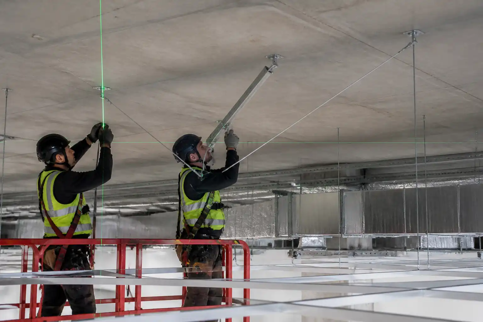
This method statement defines the detailed procedure for installation of seismic bracing to suspended ceiling systems (T-grid and similar), including verification of structural supports, layout compliance with approved seismic design, connection inspections, QA/QC inspections, hold/witness points, and final structural stability verification prior to ceiling closure and handover.
Inclusions
- Review and verification of base support structure and anchorage capacity.
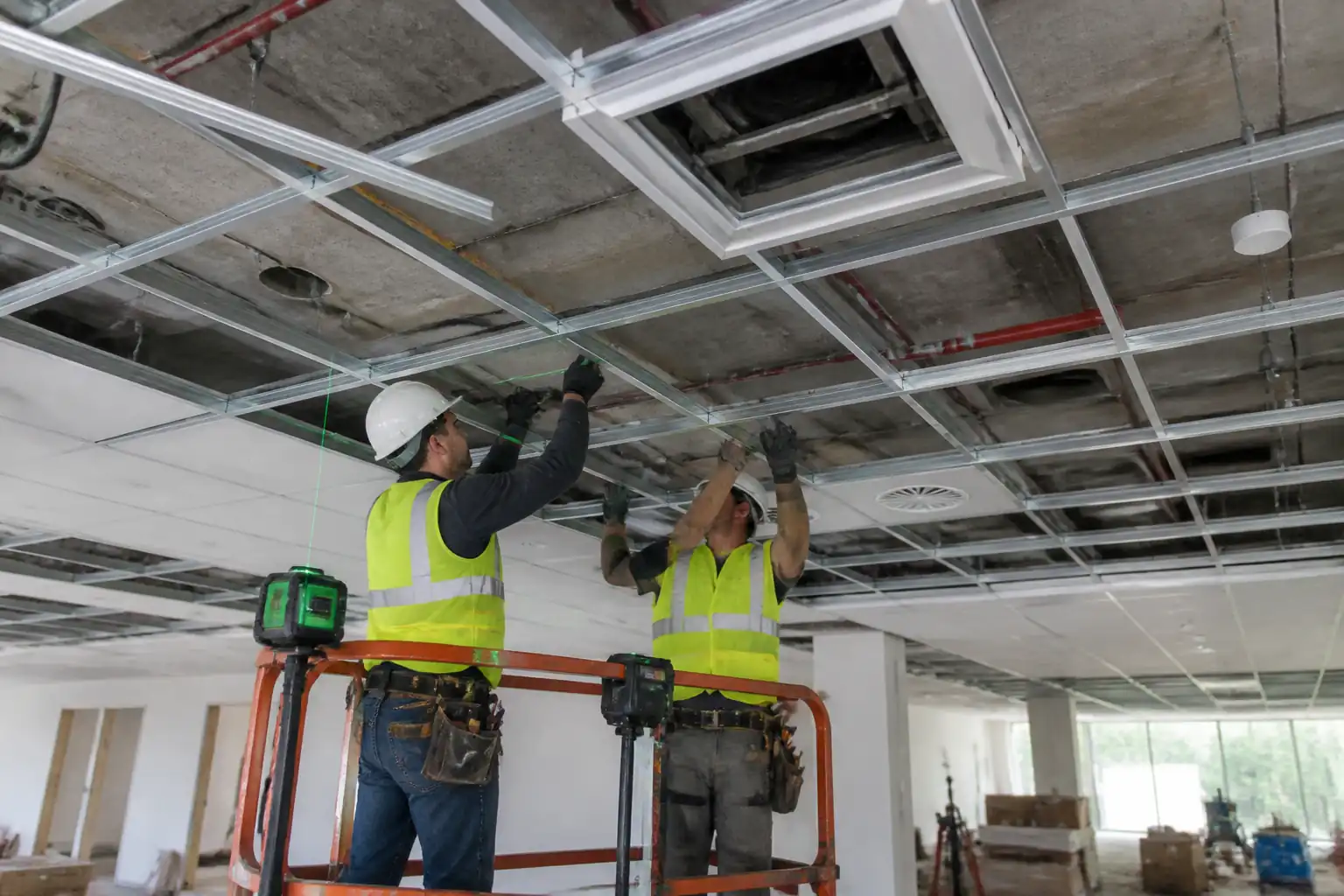
- Installation of hangers, grid, seismic splay wires, rigid compression struts, perimeter fixed and slotted/sliding connections, seismic separation joints, and stabilization of service fixtures (lights, diffusers, access panels).
- Coordination with MEP and fire protection to ensure independent support and seismic clearances.
- Inspection and testing: anchor proof testing, bracing verification, levelness and plumb tolerances, perimeter movement provisions, final sign-off prior to tile placement.
Exclusions
- Structural strengthening of base supports (if required by the Engineer).
- Design of the seismic bracing (by Designer of Record). Installer shall execute to approved shop drawings and calculations.
- Non-ceiling architectural finishes.
Location
- Applicable to all suspended ceilings within designated as requiring seismic restraint per project seismic design category and Sds parameters [Verify per project specifications].
Constraints/Key Technical Notes
- Only dry drilling methods with dust extraction in occupied buildings unless otherwise authorized.
- Power-actuated fasteners only where permitted by structural engineer and site HSE [Verify per project HSE plan and local regulations].
- Do not attach ceiling grid or bracing to non-structural members (e.g., ceiling sheetrock, cold-formed studs without load paths, or MEP services).
References
| Document Type | Reference / Number | Revision | Notes |
|---|---|---|---|
| ASCE/SEI 7 – Minimum Design Loads for Buildings and Other Structures (seismic nonstructural components). | Basis for seismic demand on ceilings and bracing [Verify project design category]. | ||
| International Building Code (IBC), seismic bracing for nonstructural components. | Where adopted by authority having jurisdiction. | ||
| CISCA Seismic Construction Handbook and Guidelines for Seismic Restraint of Suspended Ceilings. | Industry practice details for bracing, separation joints, and fixtures. | ||
| ASTM C636/C636M – Standard Practice for Installation of Metal Ceiling Suspension Systems. | General installation tolerances and practices. | ||
| ASTM E580/E580M – Application of Ceiling Suspension Systems for Acoustical Tile and Lay-in Panels in Areas Requiring Seismic Restraint. | Primary standard for seismic bracing of ceilings in the US context. | ||
| ASTM C635/C635M – Specification for Metal Suspension Systems for Acoustical Tile and Lay-In Panel Ceilings. | Component performance classes and corrosion protection. | ||
| BS EN 13964 – Suspended Ceilings – Requirements and Test Methods. | Use for EU projects; coordinate equivalence with ASTM/CISCA details. | ||
| ISO 9001 (Quality), ISO 45001 (OH&S), ISO 14001 (Environmental). | Project management system requirements [Verify per project]. | ||
| ICC-ES ESR Reports / ETA for anchors and fasteners into concrete/steel. | Use anchors with valid approvals matching base material and load direction. |
Responsibilities
| Role | Responsibility | Name / Party |
|---|---|---|
| Project Manager | Construction/Project Manager | Main Contractor |
| Engineer | Structural Engineer (Designer/RE) | Consultant |
| Engineer | Site/Field Engineer | Main Contractor |
| QA/QC | QA/QC Engineer | Main Contractor |
| HSE | HSE Officer | Main Contractor |
| Foreman/Installers | Foreman & Certified Ceiling Installers | Approved Subcontractor |
| Lab/Agency | Independent Testing Agency | Third Party |
Resources
| Resource Type | Description | Quantity | Remarks |
|---|---|---|---|
| Personnel | 4 | Full-time/part-time as per project phase | |
| Personnel | 8–12 [Verify per area size] | Adjust crew size to meet program | |
| Personnel | As required | Provide certificates prior to work |
Materials
| Material | Specification / Grade | Quantity | Remarks |
|---|---|---|---|
| T-Grid System | Manufacturer: [Submit]; Load class: [Verify] | As per drawings | Include seismic-rated clips as required |
| ASTM A641 Wire | Class 1 or better zinc coating [Verify] | As per layout | No splices; if unavoidable, per ASTM E580 with wraps [Verify]. |
| ASTM A641 Wire | With approved clips/seizing method | As per bracing plan | Provide four at each braced point unless design indicates otherwise. |
| EMT/Steel Tube | Galvanized; end-fittings per manufacturer | As per bracing plan | Fitted snug between grid and structure; caps as needed |
| Wedge/Undercut/Concrete Screw Anchors | Carbon/stainless steel grade per environment | As required | Include power-actuated fasteners only if approved |
| Seismic Perimeter Clip | Compatible with grid and wall type | As per perimeter length | Use manufacturer’s tested systems |
| Tile Hold-Down Clip | Compatible with tile/system | As per drawings/specs | |
| Bars/Hangers | Per manufacturer & code | As required | Provide safety wires |
Equipment
| Equipment | Capacity / Type | Quantity | Inspection Required |
|---|---|---|---|
| Laser Level | 2 | Calibration cert | |
| Rotary Hammer | SDS-Plus/SDS-Max | 3–4 | Pre-use check |
| Pull Tester | Up to 20–50 kN [Verify] | 1 | Calibration cert |
| Access Equipment | As needed | Daily inspections | |
| Torque Wrench | Up to 100 N·m [Verify] | 2 | Calibration cert |
| PAT Tool | 1 | Permit to work |
Prerequisites
- Approved shop drawings and seismic bracing layout, including details of braced points, splay wire angles, compression strut type, perimeter fixed/sliding connections, and separation joints.
- Designer-approved calculation package showing seismic demand on ceiling system components (Fp) and spacing of bracing lines [Verify per ASCE 7/Project Specs].
- Approved product submittals: grid system, wires, anchors with ICC-ES/ETA reports, clips, stabilizer bars, hold-down clips.
- Coordination approval with MEP and fire protection: independent supports for fixtures and flexible sprinkler drops with clearances per NFPA/Authority requirements [Verify per project].
- Access plan and PTW: work at height, PAT use (if any), hot works (if any), ceiling work in occupied areas [Verify per project HSE plan and local regulations].
- Base structure verification: drawings, as-built records, post-tension tendon/embedded services scan reports where applicable.
- Calibrations: laser level, pull tester, torque wrench valid.
- Pre-start briefing and mock-up area agreed (first-of-kind).
Method Sequence
| Step | Activity | Description | Responsibility | Inspection / Hold Point |
|---|---|---|---|---|
| 1 | Pre-start coordination and mock-up | Hold coordination meeting; confirm drawings, areas, access, and sequencing. Build first-of-kind mock-up (minimum 3x3 m) including splay wires, compression strut, and perimeter details. | Project Manager / Site Engineer / Foreman | Hold Point: Approve mock-up before bulk work. |
| 2 | Verify base structure and set-out | Confirm slab/beam/metal deck capacity and suitability. Mark grid lines, bracing lines, and perimeter clearances using laser level and control points. | Site Engineer | Witness Point: Before drilling anchors. |
| 3 | Install hanger anchors and hangers | Drill holes as per anchor ESR/ETA using specified bit and depth. Install anchors, clean holes per manufacturer (blow-brush-blow), set to required embedment. Fix 12-gauge hanger wires; twist and wrap a minimum of 3 full turns; tail ≥50 mm. | Certified Anchor Installer / Ceiling Installer | Surveillance by QA/QC |
| 4 | Anchor proof testing (sampling) | Proof test installed anchors using calibrated pull tester. | QA/QC / Independent Agency | Hold Point: Before large-scale bracing install. |
| 5 | Perimeter angle and movement provisions | Fix perimeter angles to walls/columns. Provide fixed connection on designated sides and sliding/clearance connection on orthogonal sides as per drawings. Maintain seismic perimeter gap typically 12–19 mm [Verify]. Install hold-downs where specified. | Ceiling Installer | Witness Point |
| 6 | Grid installation and leveling | Install main and cross tees to layout. Level using hangers and laser level. Do not close with tiles until bracing is complete and inspected. | Ceiling Installer | Surveillance |
| 7 | Install seismic splay wires and compression struts | At each bracing location, install four 12-gauge splay wires equally spaced around the point, splayed typically at 45° to the ceiling plane and 90° to each other in plan. Provide a rigid compression strut plumb to structure. Secure splay wires to structure and to main tee intersection using approved clips or seizing wraps (minimum 3 full turns). Tension wires to remove slack without deforming grid. | Ceiling Installer | Hold Point: Bracing installation prior to service fixtures/closure. |
| 8 | Separation joints and transitions | Install seismic separation joints across large ceiling expanses and at changes in mass/stiffness, at the spacing shown on drawings (typ. ≤12 m in each direction [Verify]). Provide trim and maintain clearances at partitions crossing through the ceiling. | Ceiling Installer | Witness Point |
| 9 | Service fixtures and MEP coordination | Provide independent support and restraint for lights, diffusers, speakers, access panels. Use stabilizer bars and safety wires. Maintain required clearances at sprinklers (e.g., 50 mm annular gap with oversized ring; flexible drops) [Verify with NFPA/local]. Do not load grid with service weights beyond rating. | Ceiling Installer with MEP Trades | Surveillance |
| 10 | Final QA/QC inspection prior to closure | Comprehensive inspection of bracing, hangers, anchors, perimeter connections, separation joints, and fixtures. Punch-list clearance before tiles/panels are installed. | QA/QC Engineer; Consultant Representative | Hold Point: Do not install tiles until approved. |
| 11 | Ceiling closure and final stability verification | Install tiles/panels and hold-down clips (where required). Conduct final walk-through to confirm no bracing was compromised during closure. Update as-builts. | Foreman / QA/QC | Witness Point |
Health, Safety, and Environment (HSE) – Safety Controls
Principal Hazards and Controls
- Hazard: Work at height (ladders/MEWPs/mobile towers)
- Likely consequence: Falls causing serious injury or fatality.
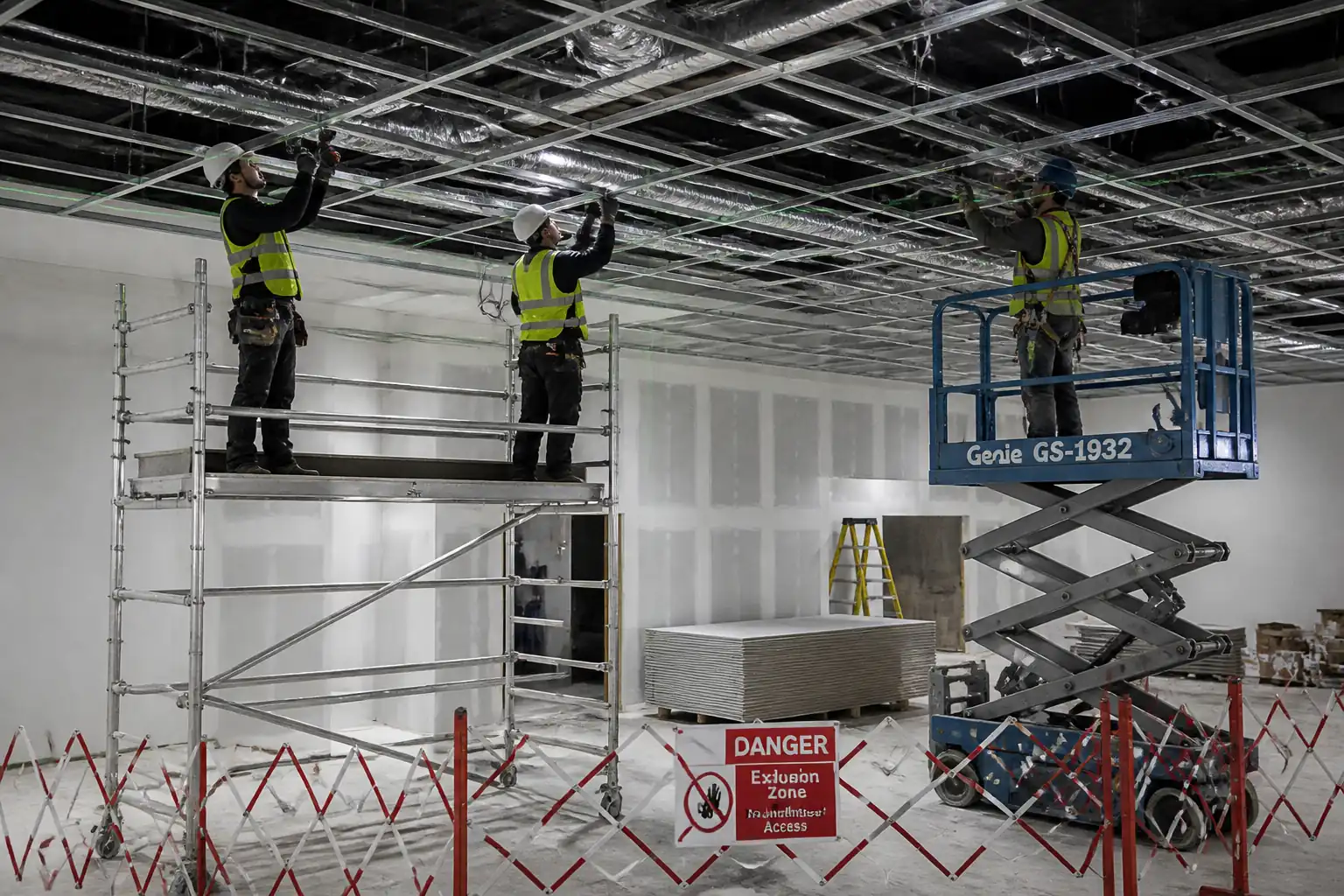
- Engineering/procedural control: Use MEWPs or podium steps on firm, level surfaces; install guardrails/toe boards on towers; maintain 3-point contact on ladders and limit task to short-duration light work only; use fall arrest only where approved anchor points exist.
- Required PPE: Hard hat, safety footwear, gloves, eye protection; fall arrest harness for MEWP if required by manufacturer/site rules.
- Collective preventive measure: Exclusion zone below; traffic marshals for MEWP; tower scaffold tags in date.
-
Inspection/permit/supervision: Daily pre-use MEWP/tower inspections; PTW for work at height; IPAF/PASMA-certified operators [Verify per project HSE plan and local regulations].
-
Hazard: Overhead drilling and anchor installation (dust, debris, eye injury)
- Likely consequence: Silica exposure, eye injury, falling debris to persons below.
- Engineering/procedural control: Use rotary hammers with integrated HEPA extraction; use debris catchers; maintain exclusion zone with barriers and signage; drilling only after service scans and permits.
- Required PPE: Safety glasses or goggles, FFP2/FFP3 respirator (or local equivalent), gloves, hearing protection, hard hat.
- Collective preventive measure: Local exhaust ventilation; schedule noisy/dusty works off-hours in occupied buildings.
-
Inspection/permit/supervision: PTW; verify scan/mark-up of PT tendons and embedded services; HSE inspections.
-
Hazard: Power-actuated tools (PAT)
- Likely consequence: Penetration into tendons/rebar; ricochet; hearing damage.
- Engineering/procedural control: PAT only where allowed, with specific permit; use proper loads/pins; no use near PT tendons or edges below manufacturer limits.
- Required PPE: Impact-rated eye protection, hearing protection, gloves, hard hat.
- Collective preventive measure: Physical barriers and signage; tool accountability.
-
Inspection/permit/supervision: PAT permit; operator license; tool condition checks.
-
Hazard: Manual handling of grid lengths, struts, and boards
- Likely consequence: Musculoskeletal injuries, cuts.
- Engineering/procedural control: Team lifts for long members; use material trolleys; pre-cut struts on workbench with clamps and guards.
- Required PPE: Cut-resistant gloves, long sleeves, safety footwear.
- Collective preventive measure: Staging areas to reduce carry distances.
-
Inspection/permit/supervision: Manual handling briefing; supervision checks.
-
Hazard: Sharp edges and flying fragments from cutting metal
- Likely consequence: Lacerations, eye injuries.
- Engineering/procedural control: Use guarded tools; deburr cut ends; end caps on compression struts.
- Required PPE: Safety glasses, cut-resistant gloves.
- Collective preventive measure: Cutting area barriers.
-
Inspection/permit/supervision: Tool inspection logs.
-
Hazard: Interaction with live electrical and fire protection systems
- Likely consequence: Electric shock; accidental sprinkler discharge/flooding.
- Engineering/procedural control: Isolate circuits where feasible; lockout/tagout; coordinate with sprinkler contractor; use flexible drops; maintain required clearances at heads.
- Required PPE: Electrical-rated gloves (when testing/isolating), eye protection.
- Collective preventive measure: Permit to work for electrical isolation; tag sprinklers under control of FP contractor.
-
Inspection/permit/supervision: LOTO permits; supervision by MEP coordinator.
-
Hazard: Overhead load release/partial ceiling collapse during install
- Likely consequence: Struck-by injuries.
- Engineering/procedural control: Sequence bracing installation before loading grid; temporary props where needed; do not stock materials on unfinished grid.
- Required PPE: Hard hat, safety boots, gloves.
- Collective preventive measure: Exclusion zones; controlled delivery to workfront.
-
Inspection/permit/supervision: Daily supervisor checks; QA/QC surveillance.
-
Hazard: Noise and vibration from drilling/cutting
- Likely consequence: Hearing loss; nuisance to occupants.
- Engineering/procedural control: Use low-vibration tools; limit duration; post notices.
- Required PPE: Hearing protection.
- Collective preventive measure: Acoustic screens if needed.
- Inspection/permit/supervision: Noise monitoring where specified.
Environmental Controls
- Dust control: Use integrated HEPA extraction for drilling; vacuum cleanup only (no dry sweeping); seal return air grilles in occupied buildings during works [Verify per building management].
- Waste management: Segregate metal offcuts for recycling; dispose of spent anchors/bits as metal waste; packaging to general recycling; maintain waste transfer notes.
- Noise and working hours: Schedule high-noise tasks within permitted hours; use acoustic enclosures for cutting stations when near sensitive receptors.
- Material selection: Use corrosion protection class suitable for environment (e.g., C3/C4 or ASTM coating class) [Verify]; prefer low-VOC sealants/adhesives if used at trims.
- Spill prevention: Store oils/greases for equipment on drip trays; immediate cleanup kits available.
- Energy and air quality: No idling for MEWPs or delivery trucks; maintain equipment to reduce emissions.
- Environmental monitoring: Where required, keep dust/noise logs and complaint registers; rectify exceedances promptly.
Quality Assurance and Quality Control
Documentation
- Approved shop drawings and calculations (with revision control).
- Manufacturer data sheets, ICC-ES/ETA anchor approvals, coating certificates.
- Calibrations for laser levels, torque wrenches, pull testers.
Hold/Witness Points
- HP1: Mock-up approval (Step 1) – Hold.
- HP2: Anchor proof test sampling (Step 4) – Hold.
- HP3: Bracing installation prior to closure (Step 7/10) – Hold.
- WP: Set-out (Step 2), Perimeter movement provisions (Step 5), Separation joints (Step 8), Closure (Step 11) – Witness.
Inspection and Testing Frequencies
- Anchor proof testing: Initial 3 per installer and substrate; then ≥2% or min 5 per area [Verify].
- Torque check: 10% of torque-controlled anchors per area [Verify].
- Levelness: Each bay; record at grid intersections at 6 m intervals [Verify].
- Splay wire/strut locations: 100% visual verification before closure.
Acceptance Criteria (typical – verify project)
- Hanger wire: Min 12-gauge; deviation ≤15° from vertical; spacing ≤1200 mm o.c. [Verify].
- Grid level: ±3 mm in 3 m; overall ±6 mm per room [Verify].
- Splay wires: Four per braced point at 45° ±10°; properly seized (≥3 full turns) with tail ≥50 mm.
- Compression strut: Rigid, snug fit; vertical tolerance ≤5 mm over strut height [Verify].
- Perimeter: Movement gap 12–19 mm continuous; fixed on one side and sliding on orthogonal side(s) as detailed; fastener spacing per drawings (e.g., ≤400 mm o.c.).
- Separation joints: Spacing per design (e.g., ≤12 m both ways) and at building seismic joints [Verify].
- Fixtures: Independently supported; safety wires installed; no net load added to grid beyond rating.
Nonconformance and Corrective Action
- Log NCRs for: failed anchors, incorrect bracing angles/spacing, missing compression struts, improper perimeter connections. Remove/replace failed anchors and re-test per ITP. Reinspect corrected works before closure.
Records and Handover
- ITP/Checklist sign-offs, pull test/torque logs, material COCs, calibration certs, as-built markups, photo records, O&M manuals with maintenance guidance for seismic components.
Attachments
- Example: Seismic Ceiling Bracing Checklist (fillable PDF)
- Example: Anchor Installation & Proof Test Log (fillable)
- Example: Pre-closure Inspection Punch-list Template
- Example: Daily Work at Height Inspection Sheet
- Example: As-built Markup Legend for Seismic Bracing Lines
- Manufacturer installation manuals and ICC-ES/ETA reports for anchors and clips
This content is a read-only public reference. Download or customize to get an editable version.
ITP preview
The first inspection activities from the linked ITP for Method Statement: Seismic Bracing Installation for Suspended Ceiling Systems:
| Activity | Inspection / Test | Acceptance Criteria | Responsibility | Record |
|---|---|---|---|---|
| Pre-start documentation review | Verify approved drawings, calculations, product submittals, calibration certs. | All current revisions approved; certificates valid. | QA/QC Engineer / Consultant | ITP checklist; submittal log |
| Base structure verification & set-out | Check support type, PT/service scan results; layout vs drawings. | Safe drilling zones confirmed; layout within ±5 mm. | Site Engineer / HSE / Consultant | Set-out record; PTW; scan report |
| Hanger anchor installation | Embedment, edge distance, hole cleaning method, torque (if applicable). | Per ESR/ETA and manufacturer [Verify]. | QA/QC Engineer / Installer | Anchor install log; torque log |
Showing 3 of 11 inspection activities. View full ITP →
Related Inspection and Test Plan
An Inspection and Test Plan (ITP) is available for Method Statement: Seismic Bracing Installation for Suspended Ceiling Systems. The ITP defines the inspection activities, acceptance criteria, hold and witness points, responsible parties, and records required to verify the work described in this method statement.
View the Method Statement: Seismic Bracing Installation for Suspended Ceiling Systems ITP →Frequently asked questions
Continue with related Quollnet resources connected to this method statement.