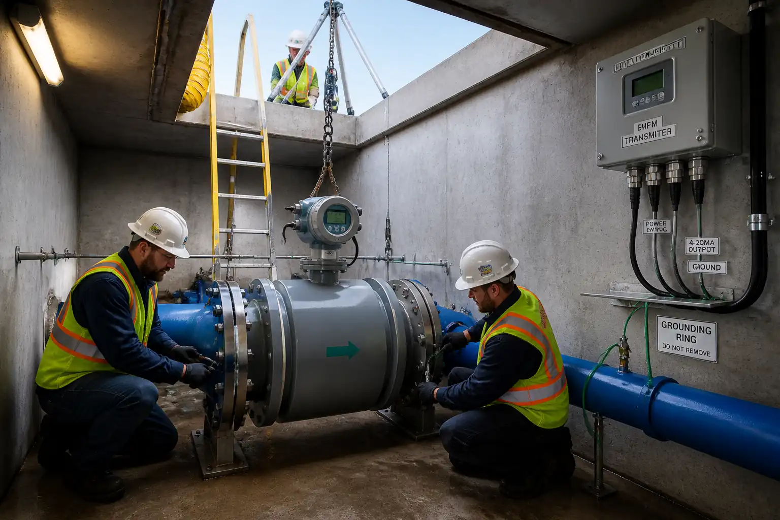

Method Statement: Installation of Electromagnetic or Ultrasonic Flow Meters on Water Networks – Method Statement
AI-assisted method statement with matching ITP, PDF download, and Excel export.
More than a static template
Unlike a downloadable Word or PDF template, this method statement is an AI-assisted editable starting point connected directly to a matching Inspection and Test Plan. Every section is structured, project-adaptable, and ready to export.
- AI-assisted drafting — Customize every section with AI for your specific project scope.
- Linked ITP — A matching inspection and test plan is generated alongside the method statement.
- Multiple export formats — Download as a formatted PDF or editable Excel spreadsheet.
- Editable starting point, not a final document — Review, verify, and adjust all content against your project requirements before use.
Static template vs. Quollnet workflow
| Feature | Static template | Quollnet |
|---|---|---|
| Project-specific content | Manual fill-in required | AI-assisted customization |
| Linked ITP | Separate document, no link | Matching ITP included |
| Export formats | Usually PDF only | PDF and Excel |
| Structured sections | Free-form layout | 13 standardized sections |
| Saved to your account | Local file only | Cloud-saved, reusable |
| Content accuracy | You verify everything | AI-assisted, you still verify |
| Cost | Often free but time-intensive | Free to customize and download |
What you can customize
When you save this method statement to your account, every section becomes editable. The following 13 sections are included:
- Scope — Defines the activity and its boundaries.
- References — Standards, specifications, and drawings.
- Responsibilities — Roles and accountabilities.
- Resources — Labour, plant, and equipment summary.
- Materials — Materials and compliance requirements.
- Equipment — Tools and equipment details.
- Prerequisites — Hold points and pre-conditions.
- Method sequence — Step-by-step construction sequence.
- Safety controls — HSE risk controls and PPE.
- Environmental controls — Environmental mitigation measures.
- QA/QC — Quality inspection and test requirements.
- ITP — Inspection and Test Plan table (has its own page).
- Attachments — Referenced drawings and documentation.
Why this method statement is used
This method statement is used to define and communicate the approved procedure for carrying out method statement: installation of electromagnetic or ultrasonic flow meters on water networks on site. It ensures the work is planned in advance, the correct resources and controls are in place, and all personnel understand responsibilities, sequence, quality requirements, and safety controls before work begins. It aligns site execution with the documented scope and acceptance expectations.
Who uses this method statement
This method statement is used by contractors, site supervisors, project engineers, QA/QC engineers, HSE officers, consultants, and client representatives. It serves as a shared reference for planning, execution, supervision, inspection, and approval of the activity on site.
When it is prepared and submitted
The method statement is prepared before the work activity starts and submitted as part of the pre-construction documentation package for review and approval.
Who reviews or approves it
The method statement is usually submitted to the client representative, consultant, resident engineer, or project management consultant for review and approval before the work commences.
Important approval note
This method statement is an AI-assisted editable starting point, not a pre-approved document. Before use on any project, all content must be reviewed and approved by the relevant parties (superintendent, principal contractor, or client representative) in accordance with your contract and project quality plan.
For example: if your specification requires a departure from a referenced standard, that departure must be documented and approved separately — this method statement will not capture that automatically. Always verify against your applicable drawings, specifications, and regulatory requirements.
Method statement content
Scope
Work included
- Installation of electromagnetic or ultrasonic (in-line spool or clamp-on) flow meters on potable or raw water closed-pipe networks.
- Verification and provision of upstream/downstream straight lengths and flow conditioning as required by manufacturer.
- Installation of earthing/grounding rings and equipotential bonding for mag meters, especially on non-conductive or lined pipes.
- Mechanical works: pipe cutting, spool insertion, flange alignment, gaskets, bolting, supports, and reinstatement.
- Electrical/instrumentation works: transmitter mounting, power and I/O cabling (4–20 mA, pulse, Modbus/RS485/Ethernet), shielding/earthing, loop checks, and labeling.
- Commissioning: configuration, zeroing, empty-pipe detection checks, leak/pressure testing, and calibration verification against certificates or reference method.
- Documentation: as-built redlines, torque records, test sheets, verification reports, and O&M handover.
Exclusions
- Permanent bypass line construction unless noted otherwise.
- Civil works beyond minor plinths/supports and chamber refurbishment.
- Network shutdown planning by others (operator to issue shutdown permit).
References
| Document Type | Reference / Number | Revision | Notes |
|---|---|---|---|
| Standard | ISO 6817 | ||
| Standard | ISO 4064 | For accuracy classes and verification where specified | |
| Guidance/Manual | Manufacturer / AWWA M33 | Follow vendor straight-run, coupling, and diagnostic requirements | |
| Standard | IEC 61010-1 / IEC 61326-1 / IEC 60529 | ||
| Standard | IEC 60364 | ||
| Standard | ASME B16.5 / EN 1092-1 / ASME PCC-1 | ||
| Standard | NSF/ANSI 61 / BS 6920 | ||
| Standard | AWWA C600/C605 |
Responsibilities
| Role | Responsibility | Name / Party |
|---|---|---|
| Construction Manager | Construction Manager | Contractor |
| Project Engineer | Site/Project Engineer | Contractor |
| HSE Officer | HSE Officer | Contractor |
| QA/QC Inspector | QA/QC Inspector | Contractor |
| Mechanical Supervisor | Mechanical Supervisor | Contractor |
| Instrumentation Supervisor | Instrumentation Supervisor | Contractor |
| Engineer | Engineer/Employer’s Representative | Employer |
Resources
| Resource Type | Description | Quantity | Remarks |
|---|---|---|---|
| Manpower | 1 | 1 | |
| Manpower | 2–4 | 2-4 | |
| Manpower | 1–2 | 1-2 | |
| Manpower | 1 | 1 | |
| Manpower | 1 | 1 | |
| Manpower | 1 (shared) | 1 | |
| Manpower | 1 (shared) | 1 |
Materials
| Material | Specification / Grade | Quantity | Remarks |
|---|---|---|---|
| Flow meter | Size per line DN; Pressure rating PN16/PN25 or Class 150/300 [Verify] | ||
| Grounding ring | To suit pipe ID/liner; bonding cable ≥16 mm² Cu [Verify] | ||
| EPDM/NBR/PTFE gasket | To flange standard ASME B16.5/EN 1092; thickness 3 mm typical [Verify] | ||
| Studs/bolts/nuts | SS A4-80 or hot-dip galvanized Grade 8.8 with compatible nuts/washers [Verify] | ||
| Instrument cable & glands | Twisted shielded pair 0.75–1.5 mm²; IP68 brass/SS glands with earth tag [Verify] | ||
| Brackets, anchors, plinth | SS304/316 brackets; anchors to suit substrate | ||
| PTFE tape, anaerobic sealant, acoustic gel | Potable-water-safe where exposed; temp range per vendor |
Equipment
| Equipment | Capacity / Type | Quantity | Inspection Required |
|---|---|---|---|
| Chain block/hoist | >1.5× load [Verify] | As required | Yes |
| Torque wrench & hydraulic torque (if required) | Up to flange spec | 1 set | Yes |
| DMM, 500 V IR tester, loop calibrator (4–20 mA) | 1 set | Yes | |
| Reference flow meter | Accuracy ≤±1% of reading [Verify] | 1 | Yes |
| Tripod, winch, harness, gas detector, blower | 1 set | Yes | |
| Submersible pump/hoses | Flow ≥ expected ingress | As required | Yes |
| Certified tools with guards/RCDs | As required | Yes |
Prerequisites
- Approved method statement, risk assessment, and ITP.
- Vendor documents: GA drawings, wiring diagrams, installation manuals, calibration certificates (ISO/IEC 17025 preferred) and IP rating confirmation.
- Permits: Network shutdown/isolation, confined space entry (if applicable), electrical work permit, lifting permit, excavation/utility permit (if any) [Verify per project HSE plan and local regulations].
- As-built survey of pipeline: pipe size, material, lining, wall thickness, available straight lengths, access, chamber condition, and existing supports.
- Confirmation of power supply (e.g., 230 VAC or 24 VDC), SCADA/RTU interface details, signal ranges, and addressing.
- Materials and tools inspected; calibration certificates current (<6–12 months) [Verify per project].
- Pre-start coordination meeting and toolbox talk with all trades; emergency plan briefed.
- Bypass/temporary supply arrangement in place if service continuity required [Verify].
Method Sequence
| Step | Activity | Description | Responsibility | Inspection / Hold Point |
|---|---|---|---|---|
| 1 | Site establishment and verification | Confirm location, pipe details, meter type, and tag numbers; verify access and lifting plan. | Site Engineer | Pre-start check |
| 2 | Isolation, lockout, and draining | Shut valves; apply LOTO; depressurize and drain the pipe section. Provide dechlorination for potable water discharge where required. | Mechanical Supervisor | Witness |
| 3 | Access and confined space controls | Open chamber/manhole; test atmosphere; set tripod/winch and ventilation if entry required; install barriers and signage. | HSE Officer | Hold point |
| 4 | Pipe preparation | Remove existing spool/blank; clean flange faces; verify flange rating and bolt pattern; check supports. | Mechanical Supervisor | Surveillance |
| 5 | Confirm straight-run and orientation | Measure upstream/downstream lengths and decide on flow conditioner if required. Mark installation orientation (arrow with flow; electrodes horizontal for mag). | Site Engineer | Hold point |
| 6 | Earthing/grounding provisions (mag meters) | Install SS grounding rings (both sides where non-conductive or lined pipe); bond meter body and pipeline to local earth bar with ≥16 mm² Cu cable [Verify]. | Instrumentation Supervisor | Witness |
| 7 | Meter mechanical installation | Install gaskets; align meter spool with pipe; insert bolts; tighten in star pattern using calibrated torque; support meter to avoid nozzle loads. | Mechanical Supervisor | Witness |
| 8 | Transmitter mounting | Mount transmitter remotely or integral per IP/temperature constraints; orient display for readability; provide sunshield if outdoors. | Instrumentation Supervisor | Surveillance |
| 9 | Cabling and terminations | Route power and signal cables in separate conduits; install glands; terminate per wiring diagram; ground shields at one end (typically transmitter). | Electrician/Instrument Tech | Surveillance |
| 10 | Functional setup | Configure meter size, K-factor/pipe factors, range, output scaling (4–20 mA, pulse), units, damping, empty-pipe detection, conductivity threshold (mag). | Instrument Tech | Witness |
| 11 | Hydrostatic/leak test of installed section | Re-pressurize gradually; vent air; hold at test pressure as per spec; inspect for leaks and flange integrity. | Mechanical Supervisor | Hold point |
| 12 | Zeroing and empty-pipe check (mag) / acoustic path check (ultrasonic) | With no flow, perform zero calibration; verify empty-pipe alarm; for clamp-on set path, verify signal strength and SNR. | Instrument Tech | Witness |
| 13 | Calibration verification | Verify against factory certificate and perform in-situ verification using vendor tool or portable reference meter; perform two-point flow check if feasible. | QA/QC + Instrument Vendor Rep (if specified) | Witness/hold |
| 14 | Loop check to SCADA/RTU | Simulate 4–20 mA and digital outputs; confirm readings, scaling, and alarms at control system. | Instrument Tech + SCADA Engineer | Witness |
| 15 | Finalization and handover | Labeling; tidy cables; restore area; remove LOTO; update as-builts; hand over dossiers. | Site Engineer | Final inspection |
Health, Safety, and Environment — Safety Controls
For each significant hazard, the following are defined: hazard, likely consequence, control, PPE, collective measure, inspection/permit/supervision.
1) Pressurized water release
- Consequence: Struck-by, drowning, property damage.
- Control: Formal isolation and LOTO of upstream/downstream valves; verify zero pressure via vent/pressure gauge before opening.
- PPE: Face shield, safety glasses, waterproof gloves, protective clothing, safety boots.
- Collective: Barriers/exclusion zones; gradual repressurization with vents open.
- Inspection/Permit: Isolation plan approved; LOTO register; supervisor sign-off.
2) Confined space in valve chamber/vault
- Consequence: Asphyxiation/toxic exposure, falls, entrapment.
- Control: Gas test (O2/LEL/H2S/CO), forced ventilation, standby attendant, retrieval system; limit occupancy time.
- PPE: Harness with retrieval line, gas monitor, helmet with chin strap, gloves.
- Collective: Tripod/winch and guardrails at opening; rescue plan with practiced drill.
- Inspection/Permit: Confined Space Entry Permit; continuous gas monitoring; competent CSE supervisor.
3) Lifting and handling of heavy meters/spools
- Consequence: Crush injuries, dropped objects, musculoskeletal injury.
- Control: Use certified lifting gear and rated anchor points; tag lines; no manual lift above 25 kg; follow lift plan.
- PPE: Hard hat, safety boots, gloves; high-visibility vest.
- Collective: Exclusion zone; banksman control.
- Inspection/Permit: Lifting plan and equipment certificates; pre-lift checklist; appointed person supervision.
4) Electrical shock/short circuits
- Consequence: Electric shock, burns, arc flash (low risk at LV), equipment damage.
- Control: Isolate circuits; test-before-touch; RCD-protected temporary supplies; correct IP-rated glands and earthing.
- PPE: Insulated gloves appropriate to voltage, eye protection.
- Collective: Lockable isolators; segregated cable trays.
- Inspection/Permit: Electrical work permit; inspections by competent electrician.
5) Underground utility strike (if excavation for access/reroute)
- Consequence: Electrocution, flooding, service outages.
- Control: Utility maps and cable/pipe locators; hand-dig trial holes; permit-to-dig.
- PPE: Dielectric boots/gloves as required; eye protection.
- Collective: Physical barriers and spotting.
- Inspection/Permit: Permit-to-dig; supervision by Site Engineer.
6) Hot work (if grinding/cutting required)
- Consequence: Fire, burns, fumes.
- Control: Avoid where possible; if unavoidable, use hot work permit, fire watch, spark containment, extinguishers.
- PPE: Flame-resistant clothing, face shield, gloves, hearing protection.
- Collective: Fire blankets; designated hot-work zone.
- Inspection/Permit: Hot work permit; atmosphere check; fire watch log.
7) Slip/trip/fall in wet chambers
- Consequence: Injury from falls and impacts.
- Control: Keep hoses/cables managed; anti-slip mats; adequate lighting and sump pumps.
- PPE: Non-slip boots, headlamp.
- Collective: Housekeeping audits; access ladders secured.
- Inspection/Permit: Supervisor inspections; housekeeping checklist.
8) Chemical exposure from chlorinated water (disinfection or residuals)
- Consequence: Skin/eye irritation, environmental harm.
- Control: Neutralize with sodium thiosulfate where required; avoid aerosolization; controlled discharge.
- PPE: Chemical-resistant gloves, goggles/face shield.
- Collective: Bunded area for dosing; eyewash available.
- Inspection/Permit: Method approved by operator; COSHH/SDS available [Verify per project HSE plan and local regulations].
Environmental Controls
- Water discharge management: Route drained water to approved outfall; for chlorinated water, dechlorinate to ≤0.02 mg/L total residual chlorine before discharge [Verify per authority].
- Sediment control: Use silt socks/sediment tanks to prevent turbidity in receivers.
- Noise/vibration: Limit working hours; use low-noise tools; monitor if near receptors.
- Waste management: Collect spent gaskets, packaging, and scrap metal for recycling; dispose of oily rags and used couplant as per waste codes.
- Spill prevention: Store oils/chemicals in bunded trays; spill kit available; immediate cleanup logged.
- Material compliance: All wetted materials to be NSF/ANSI 61 or BS 6920 compliant for potable systems [Verify].
- Biodiversity/heritage: Stop work and notify if protected species or artifacts encountered [Verify per project HSE plan and local regulations].
QA/QC
Hold and witness points
- Hold: Confined space permit approval; straight-run verification; hydrostatic test; calibration verification.
- Witness: Earthing continuity; flange torque; loop checks; zeroing/diagnostics.
Inspection and test records
- Material certificates for meter, rings, gaskets, bolts (potable water compliance where applicable).
- Calibration certificates for test equipment (DMM, IR tester, torque wrench, reference flow meter).
- Straight-run measurement sheet and orientation photos.
- Torque logs with wrench ID and setting.
- Earthing/continuity test sheet (≤1 Ω, or per project spec [Verify]).
- Insulation resistance test results for power and I/O (≥1 MΩ at 500 Vdc, unless vendor imposes lower test voltage).
- Hydrostatic/Leak test report (pressure, duration, acceptance per spec).
- Configuration/parameter sheet (range, scaling, units, outputs, damping, addresses).
- Loop check sheets with as-found/as-left values.
- Calibration verification report with comparison data and uncertainty statement.
Acceptance criteria (typical benchmarks – verify per project/manufacturer)
- Straight runs: Mag meter ≥10D upstream/≥5D downstream; with conditioner ≥5D/≥3D. Ultrasonic ≥10D/≥5D; up to 20D upstream after elbows/pumps.
- Orientation: Flow arrow with actual flow; mag electrodes horizontal; full pipe at meter location.
- Earthing: Continuity to earth ≤1 Ω; bonding cable cross-section ≥16 mm² Cu [Verify].
- Wiring: Correct cores and shields; IR ≥1 MΩ; segregation of power/signal maintained.
- Torque: To vendor/flange table; retorque after 24 hours if specified.
- Hydro/leak: No visible leaks; pressure hold per spec with allowable drop per code [Verify].
- Meter performance: Mag ±0.5…±1.0% of rate; ultrasonic ±1…±2% of rate in verification tests [Verify].
- SCADA: 4–20 mA linearity within ±0.5% span; correct alarm/status mapping.
Attachments
- Approved drawings: P&IDs, instrument index, cable schedules, GA details of meter installation.
- Manufacturer’s installation, operation, and maintenance manuals.
- Calibration and verification certificates (factory and field), ISO/IEC 17025 where applicable.
- Material test certificates and potable-water compliance (NSF/ANSI 61 or BS 6920).
- Risk assessment, method statement, permits (LOTO, CSE, hot work, lifting).
- Test records: torque logs, IR/continuity, hydrostatic test, loop checks, configuration printouts.
- As-built redlines and nameplate/tagging list.
This content is a read-only public reference. Download or customize to get an editable version.
ITP preview
The first inspection activities from the linked ITP for Method Statement: Installation of Electromagnetic or Ultrasonic Flow Meters on Water Networks:
| Activity | Inspection / Test | Acceptance Criteria | Responsibility | Record |
|---|---|---|---|---|
| Permits and isolation (LOTO) | Verify permits issued, valves closed/locked, zero pressure confirmed | LOTO applied and recorded; vent shows 0 barg | HSE Officer / Site Engineer | PTW & LOTO records |
| Straight-run measurement and location confirmation | Measure upstream/downstream lengths; check disturbances | Meets manufacturer/project minimum D requirements | Site Engineer / QA/QC | Straight-run sheet; photos |
| Material verification | Check meter tag, size, rating; certificates for potable compliance | Correct model/tag; certificates present and valid | QA/QC Inspector | Material inspection report |
Showing 3 of 13 inspection activities. View full ITP →
Related Inspection and Test Plan
An Inspection and Test Plan (ITP) is available for Method Statement: Installation of Electromagnetic or Ultrasonic Flow Meters on Water Networks. The ITP defines the inspection activities, acceptance criteria, hold and witness points, responsible parties, and records required to verify the work described in this method statement.
View the Method Statement: Installation of Electromagnetic or Ultrasonic Flow Meters on Water Networks ITP →