Construct DSM Cutoff Wall Checklist and QA Guide
Definition: Construct DSM cutoff wall checklist for field engineers and inspectors controlling mixing energy, overlap continuity, QA coring, and permeability performance during deep soil mixing installation.
- Track real-time torque, RPM, flow, and pressure to validate energy.
- Plan overlaps and sequencing to eliminate windows and ensure continuity.
- Execute QA coring and permeability tests to verify design intent.
- Interactive, commentable checklist with export and QR code verification.
Construct DSM cutoff wall requires disciplined controls over mixing energy, overlap continuity, QA coring, and permeability verification to deliver a continuous low-permeability barrier. This checklist targets deep soil mixing cutoff wall works and DSM barriers for groundwater control along embankments, cofferdams, and excavation perimeters. It excludes secant piles and diaphragm walls, keeping focus on wet mixing methods, data logging, and acceptance testing. By standardizing calibration, live monitoring, and test frequency, you minimize windows, segregation, and under-mixed zones that compromise hydraulic performance. The outcome is a traceable record set linking materials, equipment settings, energy curves, core strengths, and in-situ hydraulic conductivity to acceptance criteria. Use it to guide preconstruction, production, and verification—capturing photos, instrument screenshots, test IDs, and approvals. Start interactive mode to tick tasks, add comments with attachments, and export as PDF/Excel. Generate and affix the QR to field packs so crews access the latest version.
- Establish a robust QA/QC regime around DSM mixing energy, penetration/withdrawal rates, and binder dosage to achieve uniform soil–cement. Validate overlap geometry and verticality to avoid windows that create seepage pathways, and verify permeability through lab and in-situ tests tied to traceable locations.
- Drive reliability with instrumented rigs, calibrated torque, RPM, and grout flow meters logging at 1 Hz or better. Use alarms for low energy or flow anomalies, and base corrective actions on real-time dashboards and daily reviews. Align sampling, coring, and testing frequency with risk and geology variability.
- Interactive online checklist with tick, comment, and export features secured by QR code. The QR-backed workflow links field data, photos, and signatures to each task, enabling faster nonconformance closure, transparent approvals, and searchable archives for audits and closeout documentation across contractors and owner teams.
- Document wall continuity through as-built mapping of column centrelines, diameters, and overlaps. Integrate GNSS/total station coordinates, drilling depth profiles, and energy curves to demonstrate conformance. Where deviations occur, implement targeted re-mixing or grout injections and retest to confirm permeability recovery before acceptance.
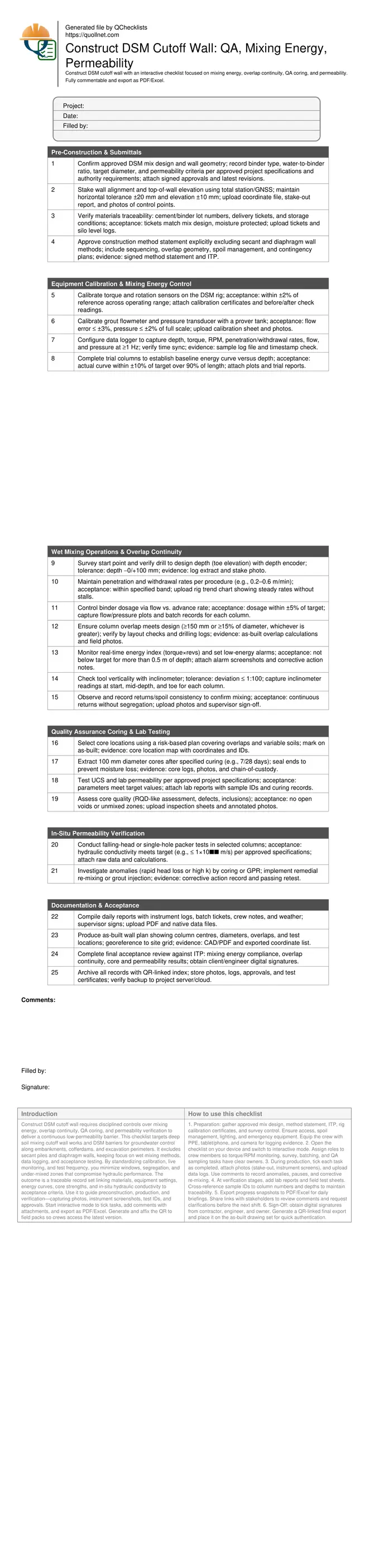
Pre-Construction & Submittals
Equipment Calibration & Mixing Energy Control
Wet Mixing Operations & Overlap Continuity
Quality Assurance Coring & Lab Testing
In-Situ Permeability Verification
Documentation & Acceptance
Control Mixing Energy for Uniform DSM Columns
Mixing energy unifies soil and binder into a low-permeability matrix. Track torque, rotation speed, penetration/withdrawal rates, grout flow, and pressure against target curves. Calibrate sensors so the energy index reflects true conditions. Use alarms to flag low energy that might create unmixed streaks or lenses. Trial columns help tune tool selection, blade wear limits, and rate bands before production. During drilling, aim for steady torque and RPM; spikes may indicate obstructions or overly rapid advance. Document any pauses and corrective passes. Align binder dosage with advance rate to avoid under-cemented zones that elevate hydraulic conductivity. Daily reviews of depth-registered plots catch trends like energy decline with wear or water ingress. When deviations occur, stop, re-mix the affected interval, and annotate logs so laboratory results correlate with field actions.
- Calibrate torque, RPM, flow, and pressure instruments.
- Log depth-indexed data at 1 Hz or better.
- Use alarms and pause to re-mix low-energy intervals.
- Tune penetration/withdrawal to maintain steady torque.
- Correlate dosage with advance rate and depth.
Assure Overlap Continuity and Verticality
Continuity depends on precise layout, verticality control, and disciplined sequencing. Set out centers with the required offset to achieve designed overlaps, and verify with survey before drilling. Inclinometer checks at start, mid, and toe keep deviations within tolerance. Plan a systematic column sequence to minimize time between adjacent columns, preventing slurry loss and soil relaxation that can open windows. Review returns visually to confirm intermixing at overlaps. Where verticality or position drifts, adjust subsequent centrelines or perform corrective columns. Document each overlap’s achieved geometry in an as-built and flag any potential gaps for targeted verification. Avoid mixing adjacent columns too far apart in time or depth; consistent energy during overlap passes is essential for continuity.
- Stake centers to deliver the designed overlap.
- Check verticality; target deviation ≤ 1:100.
- Sequence columns to limit gap time between overlaps.
- Inspect returns for continuous intermixing.
- Record achieved overlaps in as-built maps.
Verify Performance with Coring and Permeability Testing
QA coring and permeability testing demonstrate the cutoff’s hydraulic integrity. Choose core locations to sample overlaps, variable strata, and critical zones such as under utilities or near tie-ins. Extract and seal cores after designated curing periods to preserve moisture. Laboratory programs typically include UCS and permeability; where needed, add index tests to diagnose variations. Complement lab work with in-situ falling-head or packer tests to confirm performance in place. If results exceed target conductivity, execute corrective re-mixing or injection and retest until compliant. Maintain traceability by linking samples to column IDs, depths, and energy logs so nonconformances can be resolved efficiently. Acceptance is based on meeting permeability targets and demonstrating continuity, not on structural capacity.
- Select cores using a risk-based plan.
- Seal and label cores with chain-of-custody.
- Test UCS and permeability against targets.
- Use packer or falling-head tests in situ.
- Retest after any remedial works.
How to Use the DSM Cutoff Wall Interactive Checklist
- Preparation: gather approved mix design, method statement, ITP, rig calibration certificates, and survey control. Ensure access, spoil management, lighting, and emergency equipment. Equip the crew with PPE, tablet/phone, and camera for logging evidence.
- Open the checklist on your device and switch to interactive mode. Assign roles to crew members so torque/RPM monitoring, survey, batching, and QA sampling tasks have clear owners.
- During production, tick each task as completed, attach photos (stake-out, instrument screens), and upload data logs. Use comments to record anomalies, pauses, and corrective re-mixing.
- At verification stages, add lab reports and field test sheets. Cross-reference sample IDs to column numbers and depths to maintain traceability.
- Export progress snapshots to PDF/Excel for daily briefings. Share links with stakeholders to review comments and request clarifications before the next shift.
- Sign-Off: obtain digital signatures from contractor, engineer, and owner. Generate a QR-linked final export and place it on the as-built drawing set for quick authentication.
Call to Action
- Start Checklist Tick off tasks, leave comments on items or the whole form, and export your completed report to PDF or Excel—with a built-in QR code for authenticity.
- Download Excel - DSM Cutoff Wall Construction Checklist
- Download PDF - DSM Cutoff Wall Construction Checklist
- View Image - DSM Cutoff Wall Construction Checklist
Cite & Embed
“DSM Cutoff Wall Construction Checklist by Quollnet”
with a link to
this source page.
FAQ
Question: How do I know the mixing energy is sufficient throughout the DSM column?
Question: What is the best way to prove overlap continuity and avoid windows?
Question: How often should I core DSM columns for QA and what tests are typical?
Question: Which in-situ permeability tests are suitable for a DSM cutoff wall?
Related Articles
Broader reading and guidance connected to this checklist topic.


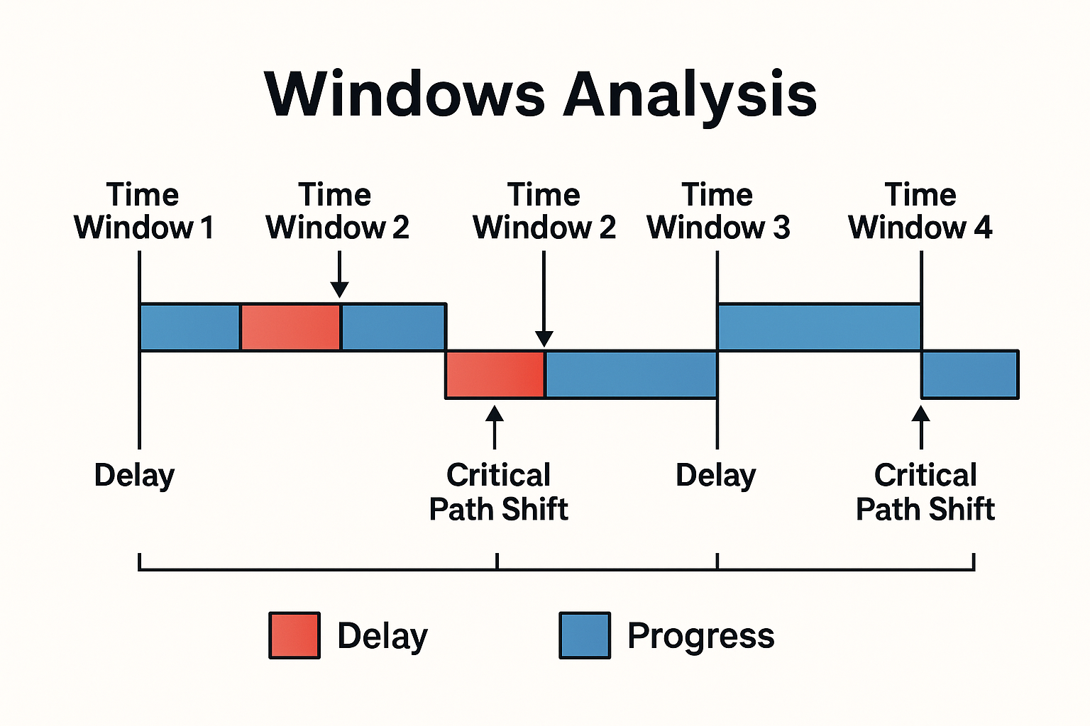
Windows Analysis | Construction Delay Evaluation Method

Master Construction Project Cashflow With Cashflowpot
Related Checklists
Keep the workflow moving with nearby templates chosen from similar checklist content.