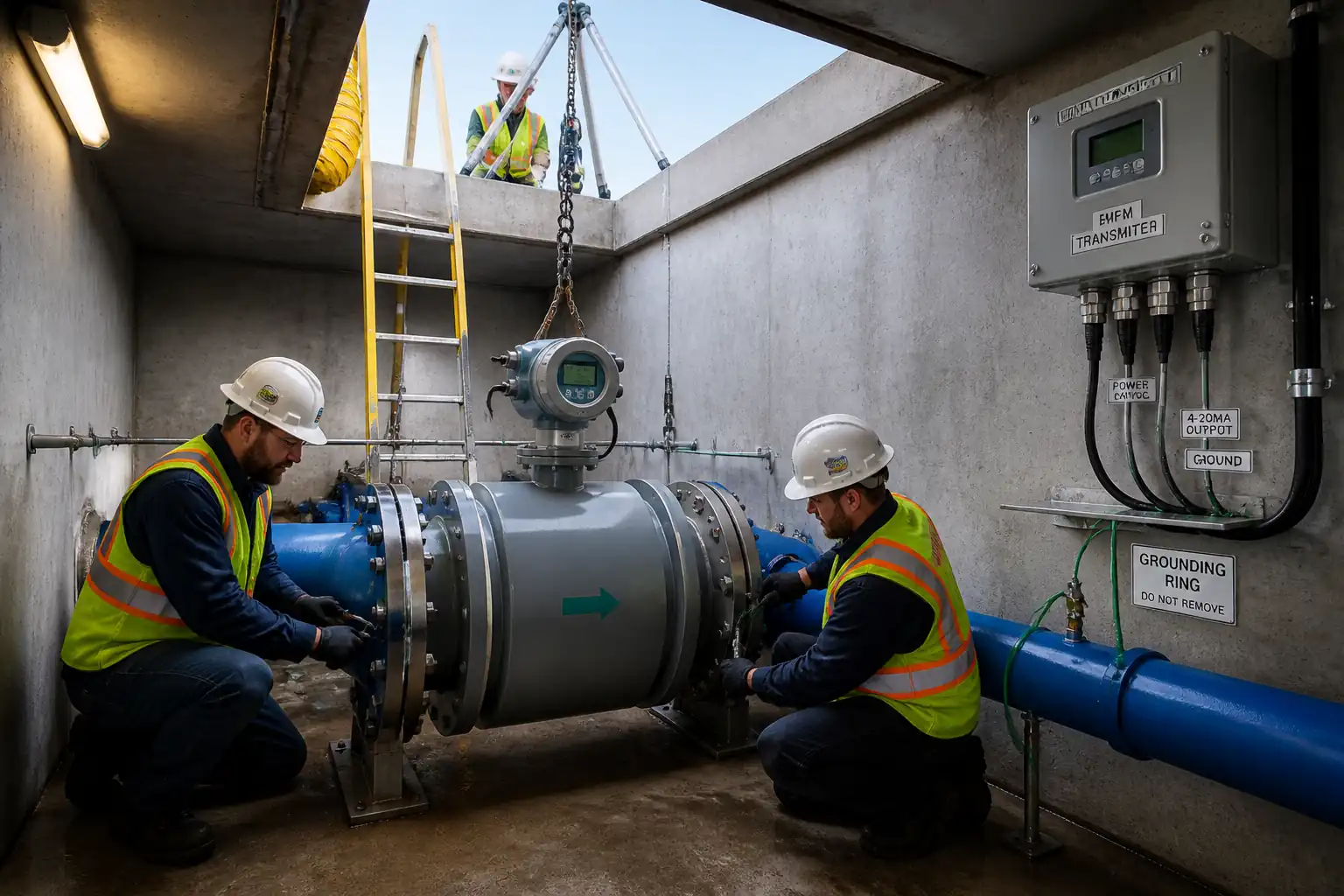

Inspection and Test Plan for Method Statement: Installation of Electromagnetic or Ultrasonic Flow Meters on Water Networks
AI-assisted inspection and test plan connected to a method statement, with PDF and Excel export.
More than a static template
Unlike a downloadable Word or PDF template, this ITP is an AI-assisted editable starting point directly connected to its method statement. Every inspection activity, hold point, and acceptance criterion is structured and ready to adapt to your project.
- AI-assisted customization — Tailor inspection activities and acceptance criteria to your specific project scope.
- Linked method statement — This ITP is connected to the corresponding method statement describing the work sequence.
- Multiple export formats — Download as a formatted PDF or editable Excel spreadsheet.
- Editable starting point, not a final document — Review and verify all content against your project specifications and standards before use.
What you can customize
When you save this ITP to your account, every inspection row becomes editable. You can add, remove, or modify:
- Inspection activity — Description of what is being inspected.
- Inspection type — Hold point (H), Witness point (W), Review (R), or Monitor (M).
- Responsibility — Contractor, subcontractor, engineer, or client.
- Frequency — How often the inspection occurs.
- Acceptance criteria — Referenced standard or specification requirement.
- Records — Forms, test reports, or checklists required as evidence.
Why this ITP is used
To provide structured inspection and testing control, ensuring installation meets technical and HSE requirements with traceable records.
Who uses this inspection and test plan
QA/QC inspectors, site engineers, instrument technicians, and the Employer’s Representative for witnessing and acceptance.
When this ITP is prepared and submitted
From pre-installation through commissioning and handover for each meter installation.
Who receives or approves this ITP
Engineer/Employer’s Representative for review, witnessing, and approval.
Inspection scope
Permits and isolation, straight-run verification, materials, flange assembly and torque, earthing, electrical tests, hydro/leak testing, zeroing/diagnostics, calibration verification, and loop checks.
Typical hold, witness, and review points
Hold: straight-run confirmation, hydro/leak test, calibration verification. Witness: earthing continuity, torqueing, loop checks.
Typical inspection records
Material certificates, torque logs, IR/continuity sheets, hydrotest report, vendor verification report, loop check sheets, configuration data, as-built photos.
Important approval note
This ITP is an AI-assisted editable starting point, not a pre-approved document. Before use on any project, all inspection activities, hold points, and acceptance criteria must be reviewed and approved by the relevant parties (superintendent, principal contractor, or client representative) in accordance with your contract and project quality plan.
Always verify acceptance criteria against your applicable drawings, specifications, and regulatory requirements. Hold points must be confirmed with the relevant authority before work proceeds past that point.
Inspection and test plan
| Activity | Inspection / Test | Acceptance Criteria | Responsibility | Record |
|---|---|---|---|---|
| Permits and isolation (LOTO) | Verify permits issued, valves closed/locked, zero pressure confirmed | LOTO applied and recorded; vent shows 0 barg | HSE Officer / Site Engineer | PTW & LOTO records |
| Straight-run measurement and location confirmation | Measure upstream/downstream lengths; check disturbances | Meets manufacturer/project minimum D requirements | Site Engineer / QA/QC | Straight-run sheet; photos |
| Material verification | Check meter tag, size, rating; certificates for potable compliance | Correct model/tag; certificates present and valid | QA/QC Inspector | Material inspection report |
| Flange face/gasket/bolt inspection | Visual examination pre-assembly | Clean undamaged faces; correct gasket and bolts | QA/QC + Mechanical Supervisor | Fit-up checklist |
| Meter orientation and arrow check | Confirm flow arrow and electrode orientation (mag) | Arrow with flow; electrodes horizontal | QA/QC / Site Engineer | Inspection record; photo |
| Bolting and torque | Torque in star pattern; verify with calibrated wrench | Torque per vendor/flange table; uniform gasket compression | Mechanical Supervisor / QA/QC | Torque log |
| Earthing/grounding (mag meters) | Continuity from meter/rings to earth bar | Resistance ≤1 Ω [Verify per project] | Instrumentation Supervisor / QA/QC | Continuity test sheet |
| Cabling IR and continuity | 500 Vdc IR test; continuity and polarity | IR ≥1 MΩ; polarity/shield termination correct | Electrician / QA/QC | Cable test results |
| Hydrostatic/leak test | Pressurize and hold per project spec | No visible leaks; hold per spec; acceptable pressure drop [Verify] | Mechanical Supervisor / QA/QC / Engineer | Pressure test report |
| Zeroing and diagnostics | Run vendor zero and diagnostics routines | Zero within vendor limit; diagnostics pass | Instrument Tech / QA/QC | Diagnostic report |
| Calibration verification | Reference comparison or built-in verification | Within stated accuracy class [Verify] | QA/QC / Vendor Rep (if specified) | Verification report; certificates |
| Loop checks to SCADA/RTU | Simulate 0/25/50/75/100% | Readback within ±0.5% span; correct scaling/units | Instrument Tech / SCADA Engineer | Loop check sheets |
| Final acceptance | Documentation, labeling, housekeeping | All records complete; punch list cleared | Engineer / QA/QC / Client | Final acceptance form |
This table is a read-only public reference. Download the PDF or Excel version, or customize this ITP to edit it for your project.
Frequently asked questions
Related method statement
This Inspection and Test Plan is associated with the Method Statement: Installation of Electromagnetic or Ultrasonic Flow Meters on Water Networks method statement, which describes the step-by-step construction sequence, resources, materials, equipment, safety controls, and environmental controls for this activity.
View the Method Statement: Installation of Electromagnetic or Ultrasonic Flow Meters on Water Networks method statement →