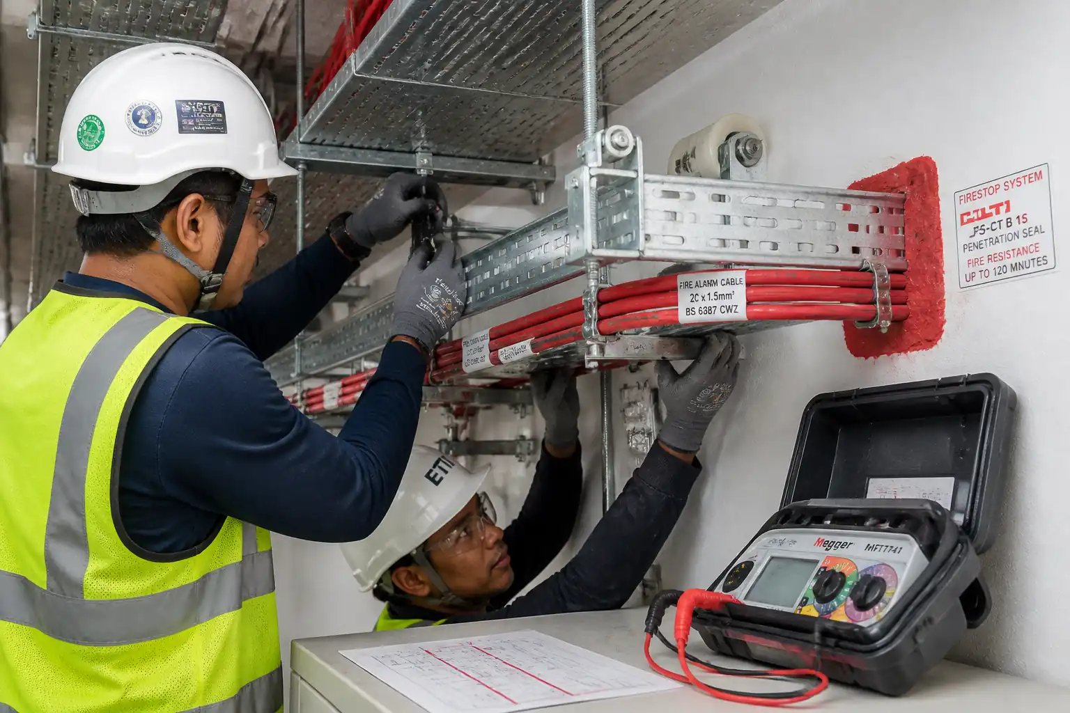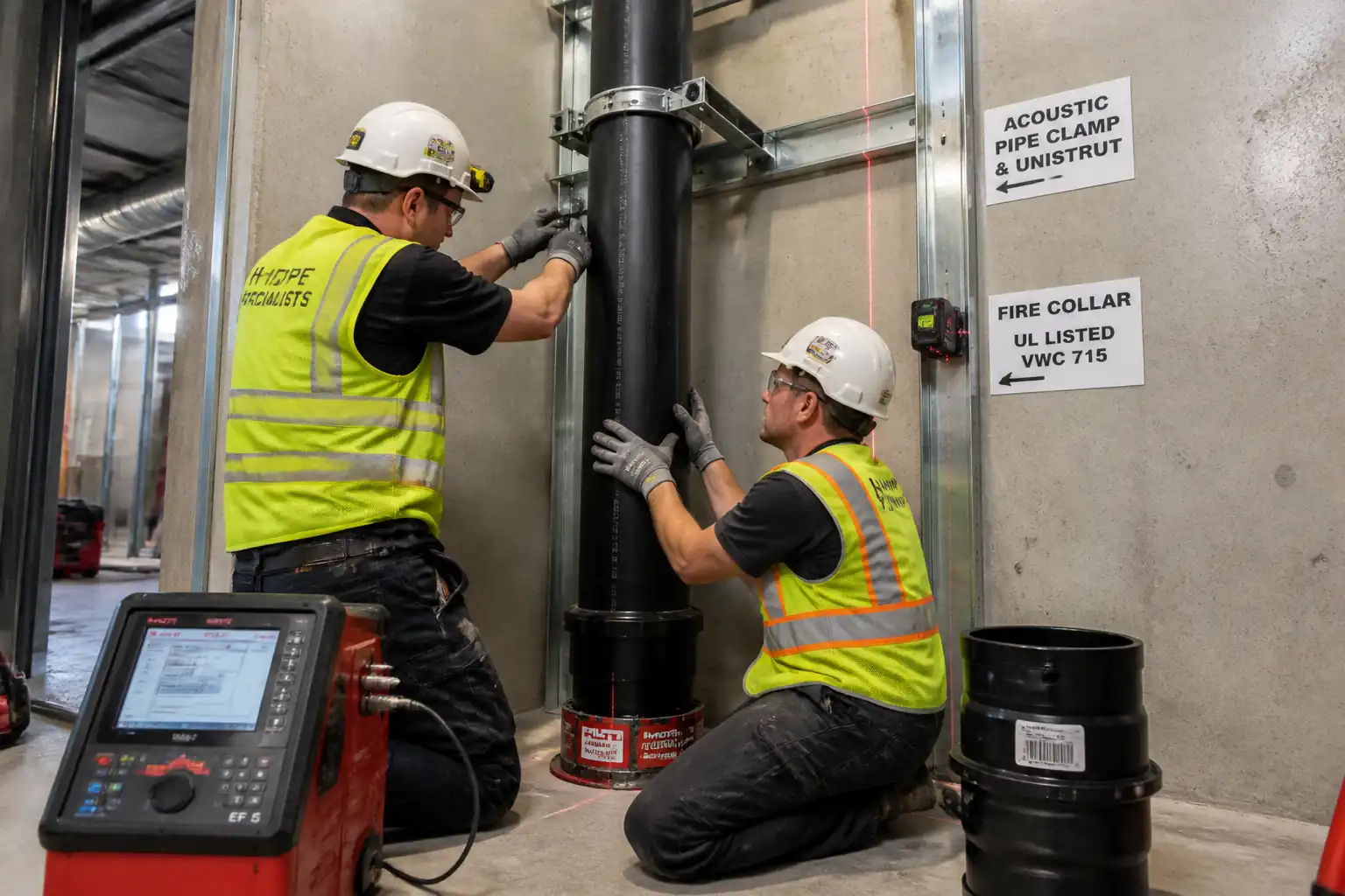

Method Statement: Installation of Busbar Trunking System (Rising Mains) with Hangers, Joints, Tap-Off Units, Expansion Joints, and Fire Barriers; Pre-energization IR Test – Method Statement
AI-assisted method statement with matching ITP, PDF download, and Excel export.
More than a static template
Unlike a downloadable Word or PDF template, this method statement is an AI-assisted editable starting point connected directly to a matching Inspection and Test Plan. Every section is structured, project-adaptable, and ready to export.
- AI-assisted drafting — Customize every section with AI for your specific project scope.
- Linked ITP — A matching inspection and test plan is generated alongside the method statement.
- Multiple export formats — Download as a formatted PDF or editable Excel spreadsheet.
- Editable starting point, not a final document — Review, verify, and adjust all content against your project requirements before use.
Static template vs. Quollnet workflow
| Feature | Static template | Quollnet |
|---|---|---|
| Project-specific content | Manual fill-in required | AI-assisted customization |
| Linked ITP | Separate document, no link | Matching ITP included |
| Export formats | Usually PDF only | PDF and Excel |
| Structured sections | Free-form layout | 13 standardized sections |
| Saved to your account | Local file only | Cloud-saved, reusable |
| Content accuracy | You verify everything | AI-assisted, you still verify |
| Cost | Often free but time-intensive | Free to customize and download |
What you can customize
When you save this method statement to your account, every section becomes editable. The following 13 sections are included:
- Scope — Defines the activity and its boundaries.
- References — Standards, specifications, and drawings.
- Responsibilities — Roles and accountabilities.
- Resources — Labour, plant, and equipment summary.
- Materials — Materials and compliance requirements.
- Equipment — Tools and equipment details.
- Prerequisites — Hold points and pre-conditions.
- Method sequence — Step-by-step construction sequence.
- Safety controls — HSE risk controls and PPE.
- Environmental controls — Environmental mitigation measures.
- QA/QC — Quality inspection and test requirements.
- ITP — Inspection and Test Plan table (has its own page).
- Attachments — Referenced drawings and documentation.
Why this method statement is used
This method statement is used to define and communicate the approved procedure for carrying out method statement: installation of busbar trunking system (rising mains) with hangers, joints, tap-off units, expansion joints, and fire barriers; pre-energization ir test on site. It ensures the work is planned in advance, the correct resources and controls are in place, and all personnel understand responsibilities, sequence, quality requirements, and safety controls before work begins. It aligns site execution with the documented scope and acceptance expectations.
Who uses this method statement
This method statement is used by contractors, site supervisors, project engineers, QA/QC engineers, HSE officers, consultants, and client representatives. It serves as a shared reference for planning, execution, supervision, inspection, and approval of the activity on site.
When it is prepared and submitted
The method statement is prepared before the work activity starts and submitted as part of the pre-construction documentation package for review and approval.
Who reviews or approves it
The method statement is usually submitted to the client representative, consultant, resident engineer, or project management consultant for review and approval before the work commences.
Important approval note
This method statement is an AI-assisted editable starting point, not a pre-approved document. Before use on any project, all content must be reviewed and approved by the relevant parties (superintendent, principal contractor, or client representative) in accordance with your contract and project quality plan.
For example: if your specification requires a departure from a referenced standard, that departure must be documented and approved separately — this method statement will not capture that automatically. Always verify against your applicable drawings, specifications, and regulatory requirements.
Method statement content
Scope
Overview
This method statement covers the complete installation of low-voltage (LV) busbar trunking systems (rising mains), including supports/hangers, jointing, alignment, expansion accommodation, tap-off units, earthing/bonding, fire and smoke sealing at floor penetrations, identification/labeling, pre-energization testing (insulation resistance and continuity), and quality control/ITP compliance. It defines the Hold Points for joint bolt torque verification and insulation resistance testing before energization.
Inclusions
- Receipt, storage, and handling of busbar trunking sections and accessories.
- Setting out, support design verification, drilling, anchoring, and installation of hangers/brackets.
- Vertical and horizontal busbar installation in risers and plant rooms, including alignment and level/plumb checks.
- Assembly and torqueing of joint kits; recording torque values.
- Installation of expansion joints/modules and thermal movement clearances.
- Installation of tap-off units at designated locations and rating verification.
- Earthing and bonding connections including to building earth bar.
- Fire and smoke stopping at each floor penetration with approved systems and manufacturer kits.
- Pre-energization tests: insulation resistance, continuity/earth bonding, and phase identification/rotation checks.
- Documentation: ITP records, checklists, redlines/as-builts, calibration certificates.
Exclusions
- Permanent civil/structural modifications beyond minor anchor fixings and sleeves.
- Upstream/downstream switchgear internal works (unless explicitly stated in project scope).
- Energization and load testing (performed by Commissioning team under separate procedure).
Interfaces
- Coordination with Structural, Architectural, Firestopping specialist, and other MEP disciplines for riser space, openings, and penetrations.
- Permit-to-Work and LOTO interfaces with existing energized equipment.
Constraints and Benchmarks
- Support spacing, joint bolt torque, expansion allowances, and minimum IR values shall follow the manufacturer’s instructions and project specifications. Where not specified, use typical industry benchmarks noted herein and verify prior to work commencement [Verify per project specifications and manufacturer data].
- Hold Points: HP-1 Joint Torque Verification; HP-2 Insulation Resistance (IR) Test Pre-energization.
References
| Document Type | Reference / Number | Revision | Notes |
|---|---|---|---|
| Standard | IEC 61439-6 | ||
| Standard | IEC 60364-6 | Use with manufacturer’s test requirements [Verify per project specifications]. | |
| Standard | BS 7671 | ||
| Standard | ASTM E814 / UL 1479 / EN 1366-3 | Select standard family per project approvals. | |
| Standard | EAD 330232; ASTM E488/E488M | Sample pull tests as specified. | |
| Standard | ISO 6789 | ||
| Standard | IEC 61557 | ||
| Standard | EN 1998-1 / ASCE 7 | Project-specific requirement. | |
| Project Doc | Supersede typical benchmarks where different. |
Responsibilities
| Role | Responsibility | Name / Party |
|---|---|---|
| PM | Authorizes works, ensures interfaces resolved. | Contractor |
| CM/SE | Coordinates permits, scaffolding/MEWP, lifting plans, and access. | Contractor |
| Supervisor | Ensures correct torque values, alignment, and labeling. | Contractor |
| QA/QC | Verifies materials, calibration, test results, and records. | Contractor |
| HSE | Toolbox talks, inspections, incident control. | Contractor |
| Surveyor | Sets reference lines and benchmarks. | Contractor |
| Specialist | Ensures listing compliance and documentation. | Approved Subcontractor |
| OEM Rep | Attend critical inspections/hold points if specified. | Manufacturer |
| Engineer | Approves inspection results and releases for next stage. | Client/Consultant |
Resources
| Resource Type | Description | Quantity | Remarks |
|---|---|---|---|
| Labor | Installation, alignment, lifting and jointing. | As per manpower plan | |
| Labor | Provide access platforms and safe working positions. | As required | |
| Labor | Install tested fire barrier systems. | As required |
Materials
| Material | Specification / Grade | Quantity | Remarks |
|---|---|---|---|
| Copper/Aluminium conductors per spec | As per BOQ | ||
| Per joints | |||
| HDG steel | |||
| SS/Carbon steel HDG | |||
| Sealants, boards, wraps, collars as listed | |||
| Copper/SS | |||
Equipment
| Equipment | Capacity / Type | Quantity | Inspection Required |
|---|---|---|---|
| Sufficient sets | |||
| Up to 1 kV DC | 1+ | ||
| As needed | |||
| 1+ | |||
| SWL marked | As required | ||
| As required | |||
| As required | |||
| 1 | |||
| 1+ |
Prerequisites
- Approved shop drawings, coordination drawings, and method statement/ITP.
- Material submittals approved; delivery inspected; storage dry and level; packaging intact.
- Structural approval for supports/hangers; anchor types confirmed per substrate and fire rating requirements.
- Riser openings prepared; edge protection/guardrails installed; working platforms/scaffolds inspected and tagged.
- Permits to Work: Hot works (if any), Working at Height, Lifting Operations, Riser/Restricted Area access; Lockout/Tagout (LOTO) for any interfacing with existing energized equipment [Verify per project HSE plan and local regulations].
- GPR/rebar scan of drill locations completed and recorded; utilities clearance obtained.
- Tools and test equipment calibration certificates current (torque wrenches, megger, meters).
- Manufacturer’s latest installation manuals and torque charts available on site.
- Pre-start coordination meeting and task-specific toolbox talk completed; roles and Hold Points briefed.
- Firestop system selection confirmed to match floor/shaft rating and annular gaps; approved installer mobilized.
- Lifting plan and method for hoisting busbar sections in risers approved; SWL of lifting points verified or temporary lifting frames installed and inspected.
- Ambient conditions suitable: dry, clean areas; temperature within OEM limits for installation and testing [Verify per manufacturer].
Method Sequence
| Step | Activity | Description | Responsibility | Inspection / Hold Point |
|---|---|---|---|---|
| 1 | Receipt, Storage, and Inspection | Unload using appropriate lifting points; store busbar sections horizontally on level dunnage; keep dry/clean; inspect for damage and verify ratings vs submittals. | Supervisor/QAQC | Visual inspection; MIR |
| 2 | Setting Out | Mark busbar centerline, offsets, and bracket locations using laser; verify clearances from walls/other services; confirm expansion joint locations per OEM and building movement joints. | Surveyor/Site Engineer | ITP surveillance |
| 3 | Install Supports/Hangers and Brackets | Drill and fix anchors; install riser brackets at each floor and near joints; install horizontal trapeze where required. Clean holes and set anchors per ETA procedure; torque per manufacturer. | Supervisor | ITP Witness |
| 4 | Pre-Lift and Access Preparation | Install temporary lifting devices (chain blocks/gin wheel) and edge protection; verify SWL; barricade riser openings; brief crew. | Supervisor/HSE | Pre-use inspection |
| 5 | Install First (Base) Section | Position and fix the first section at the base/lowest level ensuring plumb alignment; shim and tighten supports lightly to allow adjustment. | Supervisor/Lead Electrician | Surveillance |
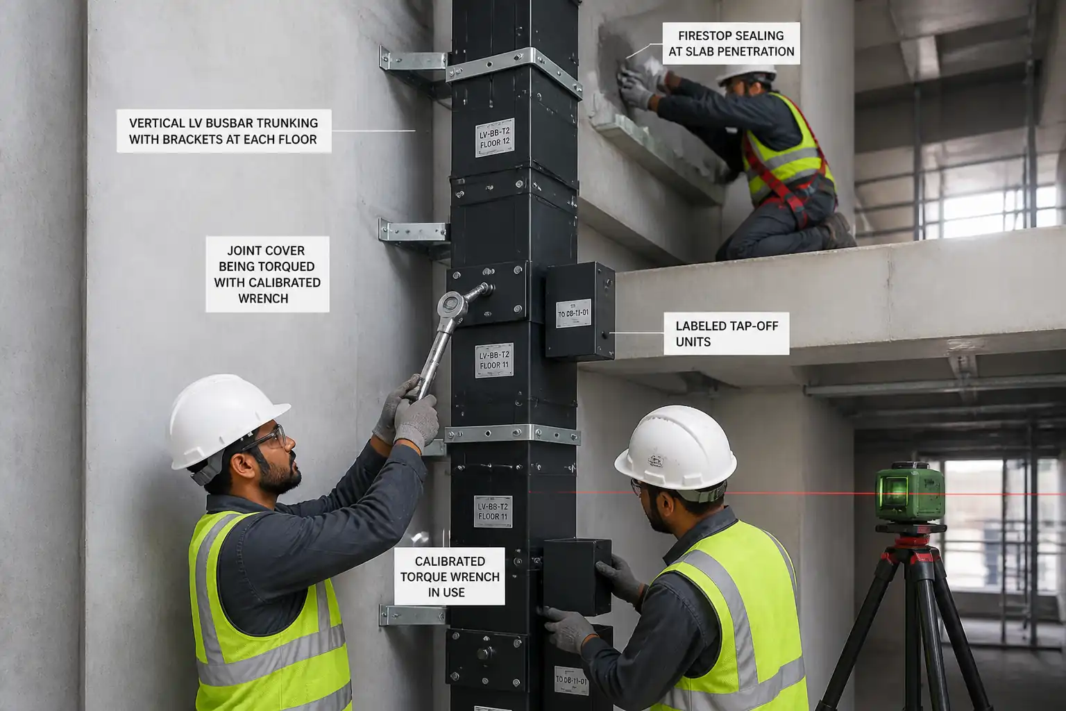
| 6 | Joint Assembly Between Sections | Align mating ends; install OEM joint kit (phase barriers, gaskets); insert/torque bolts in cross pattern to OEM-specified torque using calibrated wrench. Fit joint covers and insulation barriers. | Lead Electrician | ITP HOLD POINT HP-1 |
| 7 | Progressive Riser Build and Alignment | Lift succeeding sections, assemble joints, and fix to supports; re-check plumb every 2–3 sections and at each floor; tighten support fixings to final torque. | Supervisor | Surveillance |
| 8 | Expansion Joint Installation | Install expansion modules at designated points (e.g., near building expansion joints or at runs exceeding OEM length without compensation). Set gap per ambient temperature using OEM scale/gauge. | Lead Electrician/OEM Rep (if required) | Witness |
| 9 | Tap-off Units Installation | Confirm de-energized state. Fit tap-off units only at designated tap-off windows; ensure interlocks function; secure per OEM; install downstream cabling as per drawings. | Lead Electrician | Witness |
| 10 | Earthing and Bonding | Connect earth bars/links and bonding conductors to building main earth. Clean contact surfaces; apply anti-oxidant (if required); torque per OEM. | Electrician | Witness |
| 11 | Fire and Smoke Sealing at Floor Penetrations | Install approved firestop systems around busbar at each floor/shaft penetration per tested listing; ensure annular space, depth, and materials match approval. Affix identification label/Matrix card. | Firestop Specialist | ITP Witness (may be Hold at first installation) |
| 12 | Identification and Signage | Install permanent labels on riser, joints, tap-offs, direction of supply, safety warnings, and circuit schedules. | Supervisor | Surveillance |
| 13 | Pre-test Checks and Cleaning | Verify all covers installed, joints complete, debris removed; disconnect sensitive devices; ensure busbar is de-energized and isolated (LOTO); dry conditions. | Supervisor/QAQC | Surveillance |
| 14 | Insulation Resistance (IR) Test – Pre-energization | Test between phases and each phase to earth using 1000 V DC for 1 minute minimum (unless OEM specifies otherwise). Temperature-correct readings. Record results by section and overall. | QAQC/Tester | ITP HOLD POINT HP-2 |
| 15 | Continuity and Phase Identification/Rotation Check | Verify earth continuity and correct phase sequence from source to top; label phases if required. | QAQC/Electrician | Witness |
| 16 | Final Mechanical Inspection | Verify supports, clearances, joint covers, tap-off security, firestops, signage, housekeeping. | QAQC/Supervisor | Joint walkdown with Engineer |
| 17 | Documentation and Handover for Energization | Compile ITP packs, torque logs, calibration certs, test sheets, as-builts, OEM approvals. Request Energization Permit. | QAQC/PM | Document review |
Health, Safety, and Environment (HSE) – Safety Controls
Key Task-Specific Hazards and Controls
1) Hazard: Working at height in risers/shafts; open floor edges and voids.
- Consequence: Fall from height causing serious injury/fatality.
- Engineering/Procedural Control: Install guardrails/toe boards around openings; use certified scaffold/MEWP with fall protection anchor points; use inertia-reel fall arrest when outside protected areas; maintain exclusion zones and debris nets for multi-level works.
- Required PPE: Full body harness with double lanyard, helmet with chin strap, gloves, safety boots, eye protection.
- Collective Preventive Measure: Edge protection and fully decked platforms; fixed access ladders/stairs where possible.
- Inspection/Permit/Supervision: Daily scaffold/MEWP inspections; Working at Height permit; Supervisor and HSE inspections [Verify per project HSE plan and local regulations].
2) Hazard: Lifting/hoisting busbar sections in risers.
- Consequence: Dropped load, crush injuries, structural damage.
- Engineering/Procedural Control: Lifting plan; rated chain blocks/hoists with current certification; verify SWL of attachment points or use temporary certified lifting frames; tag lines; exclusion zone below; competent riggers only.
- Required PPE: Helmets with chin straps, gloves, steel-toe boots, eye protection.
- Collective Preventive Measure: Barricades and spotters; load path control; radio/hand-signal communications.
- Inspection/Permit/Supervision: Pre-lift checklist; lifting operations permit; appointed person supervision.
3) Hazard: Drilling into concrete (silica dust, hit rebar/services).
- Consequence: Respiratory illness; structural damage; service strike, electric shock, flooding.
- Engineering/Procedural Control: GPR/rebar scan before drilling; use dust-extraction drills; wet suppression where permitted; mark safe zones; stop work if unexpected voids encountered.
- Required PPE: FFP3/N95 respirator, safety glasses, hearing protection, gloves.
- Collective Preventive Measure: Local exhaust ventilation; isolation of affected area.
- Inspection/Permit/Supervision: Permit to drill; scan records; HSE monitoring.
4) Hazard: Electrical hazards during testing/connection.
- Consequence: Electric shock, arc flash, burns.
- Engineering/Procedural Control: LOTO on all sources; confirm de-energized with approved tester; use DC test voltages per OEM; discharge after IR tests; arc-rated PPE when working near live switchboards if any live work is unavoidable (avoid where possible).
- Required PPE: Electrically rated gloves, arc-rated clothing, face shield, insulated footwear (as applicable).
- Collective Preventive Measure: Barriers and warning signs; restricted access to test area.
- Inspection/Permit/Supervision: Electrical PTW; qualified persons only; calibrated instruments; supervision by Senior Electrician/QAQC.
5) Hazard: Manual handling of long, heavy busbar sections.
- Consequence: Musculoskeletal injuries, pinching.
- Engineering/Procedural Control: Use mechanical aids (trolleys, hoists); team lifts; plan routes; keep hands clear of pinch points; use lifting handles where provided.
- Required PPE: Gloves, safety boots.
- Collective Preventive Measure: Mechanical aids as default; minimize carry distances.
- Inspection/Permit/Supervision: Manual handling assessments; toolbox talk.
6) Hazard: Firestopping chemicals (sealants, foams) and hot works (if any).
- Consequence: Skin/eye irritation; fire.
- Engineering/Procedural Control: Use approved low-VOC products where possible; follow SDS; ensure ventilation; if hot works required, implement hot work permit, fire watch, extinguishers.
- Required PPE: Chemical-resistant gloves, goggles, coveralls; for hot works – FR clothing.
- Collective Preventive Measure: Product substitution to less hazardous; designated hot work zones.
- Inspection/Permit/Supervision: SDS available; Hot Work Permit; post-work fire watch duration per permit.
7) Hazard: Noise and vibration from drilling/cutting.
- Consequence: Hearing loss, HAVS.
- Engineering/Procedural Control: Select low-vibration tools; limit exposure durations; rotation of tasks; maintain tools.
- Required PPE: Hearing protection appropriate to dB level; anti-vibration gloves (as applicable).
- Collective Preventive Measure: Acoustic screens where feasible.
- Inspection/Permit/Supervision: Noise monitoring; HAVS records.
8) Hazard: Dropped objects in multi-storey risers.
- Consequence: Injury to persons below; equipment damage.
- Engineering/Procedural Control: Tether tools; fit toe boards and debris netting; store materials away from edges; use tool lanyards.
- Required PPE: Hard hats, safety boots, eye protection.
- Collective Preventive Measure: Exclusion zones per level; overhead protection.
- Inspection/Permit/Supervision: Daily checks; HSE audits.
9) Hazard: Inadequate anchorage or support failure.
- Consequence: Collapse of busbar run, severe damage/injury.
- Engineering/Procedural Control: Use ETA anchors; install per manufacturer; QA witness; sample pull testing; engineer review of support calcs when required.
- Required PPE: Standard site PPE; additional for drilling.
- Collective Preventive Measure: Design review; independent checks.
- Inspection/Permit/Supervision: ITP witness of supports; records of pull tests and torque.
Environmental Controls
- Dust control: Use drills with integrated dust extraction or wet methods where allowed; vacuum M/H-class cleanup; no dry sweeping.
- Noise: Schedule noisy works during permitted hours; use low-noise tools and acoustic screens where feasible; provide hearing protection zones.
- Waste management: Segregate metal offcuts for recycling; dispose of packaging, spent cartridges/foams, and chemical containers via approved waste streams; retain waste transfer notes.
- Chemical handling: Store sealants/foams in bunded trays; maintain SDS; prevent spills; use drip trays when applying overhead; spill kits available.
- Energy and emissions: Minimize idling of MEWPs and generators; use electric tools where possible; maintain equipment.
- Water protection: Prevent slurry or wash water from entering drains; collect and dispose per environmental plan [Verify per project].
- Material efficiency: Order lengths to minimize cuts; return unused sealed kits to vendor where permissible.
Quality Assurance and Quality Control (QA/QC)
- Submittals: Ensure approvals for busbar system, supports, anchors, firestop systems, and testing procedures are in place.
- Calibration: Maintain valid calibration for torque wrenches (ISO 6789), meggers and meters (IEC 61557). Keep copies on site and in the dossier.
- Sampling/Inspection Frequency: 100% visual inspection of joints and covers. Joint torque verification: 100% at HP-1 unless project specifies statistical sampling [Verify per project]. Anchor pull tests: as specified (e.g., 5% at 1.5× SWL) [Verify]. Firestop first-of-kind installation may be Hold Point.
- Acceptance Criteria Highlights:
- Alignment/plumb within tolerances specified (typical ±3 mm/m; max ±10 mm overall) [Verify].
- Joint bolts torque within OEM range; covers and phase barriers correctly installed.
- IR ≥ 1 MΩ minimum at 1000 V DC for 1 min; target ≥ 100 MΩ for new dry installation unless OEM states otherwise [Verify].
- Earthing continuity and correct phase sequence confirmed.
- Firestopping rating matches barrier rating; installation per tested listing.
- Documentation: Maintain torque logs linked to section/joint IDs; IR/continuity test sheets with instrument details; anchor test reports; firestop batch certs and photos; as-built drawings showing tap-off locations and identification.
- Nonconformance: Record NCRs for any deviations; define corrective actions; re-test after rectification.
- OEM/Engineer Involvement: Invite OEM rep for first-of-kind jointing/expansion installation and at hold points if required by spec.
Attachments
- Approved shop drawings and coordinated riser layouts.
- Manufacturer installation manuals and torque charts (latest issue).
- Material submittal approvals and Certificates of Conformance.
- Anchor ETA certificates and, if applicable, pull-test procedures and results.
- Calibration certificates for torque wrenches, meggers, and meters.
- Firestop system approvals (UL/ETA) with installation details and product batch certificates.
- Lifting plan, PTWs, LOTO records, WAH permits.
- Checklists: receipt, supports/anchors, joint assembly, firestopping, pre-test, final walkdown.
- Test records: IR tests, continuity/phase rotation, earth bonding.
- As-built drawings with tap-off indexing and identification schedule.
- NCRs/Corrective action reports (if any) and close-out evidence.
This content is a read-only public reference. Download or customize to get an editable version.
ITP preview
The first inspection activities from the linked ITP for Method Statement: Installation of Busbar Trunking System (Rising Mains) with Hangers, Joints, Tap-Off Units, Expansion Joints, and Fire Barriers; Pre-energization IR Test:
| Activity | Inspection / Test | Acceptance Criteria | Responsibility | Record |
|---|---|---|---|---|
| Materials receipt (busbar, joints, supports, anchors, firestop) | Verify submittals, ratings, certificates | Conform to approvals; no damage; certificates present | QA/QC, Engineer (Surv.) | MIR, photos |
| Setting out and clearances | Dimensional survey | Centerline and plumb/level within tolerance; clearances per OEM [Verify] | Site Engineer/QAQC | Setout record |
| Support/hanger installation and anchors | Anchor installation checks; sample pull test | Spacing/support rating per design; anchors per ETA; pull tests pass [Verify] | Supervisor/QAQC/Engineer | Support checklist; pull-test report |
Showing 3 of 11 inspection activities. View full ITP →
Related Inspection and Test Plan
An Inspection and Test Plan (ITP) is available for Method Statement: Installation of Busbar Trunking System (Rising Mains) with Hangers, Joints, Tap-Off Units, Expansion Joints, and Fire Barriers; Pre-energization IR Test. The ITP defines the inspection activities, acceptance criteria, hold and witness points, responsible parties, and records required to verify the work described in this method statement.
View the Method Statement: Installation of Busbar Trunking System (Rising Mains) with Hangers, Joints, Tap-Off Units, Expansion Joints, and Fire Barriers; Pre-energization IR Test ITP →Frequently asked questions
Continue with related Quollnet resources connected to this method statement.