Review Façade Aluminum Cladding Joint & Module Coordination
Definition: Review façade aluminum cladding joint layout and panel module coordination guides site teams to verify grid alignment, joint widths, and panel modules for buildability, tolerance compliance, drainage continuity, fire integrity, and consistent appearance.
- Aligns panel modules to control grid for consistent joint aesthetics
- Checks joint widths, cumulative drift, and movement gaps to tolerances
- Coordinates panels with windows, corners, and services to avoid small cuts
- Interactive, commentable checklist with export and QR code validation
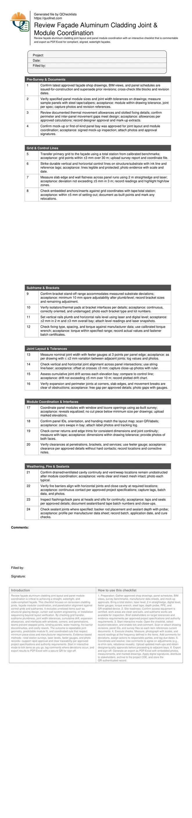
Review façade aluminum cladding joint layout and panel module coordination is critical to achieving a straight, watertight, and code-compliant façade. This checklist focuses on rainscreen cladding joints, façade modular coordination, and panelization alignment against control grids and subframes. It excludes unrelated items such as structural glazing design, curtain wall system engineering, or installation sequencing beyond layout verification. By checking grid transfer, subframe plumbness, joint width tolerances, cumulative drift, expansion allowances, and interfaces with windows, corners, and penetrations, teams prevent stepped joints, binding panels, water tracking, fire barrier discontinuities, and costly rework. The outcome is repeatable joint geometry, predictable module fit, and coordinated cuts that respect minimum piece sizes and manufacturer requirements. Evidence-based methods—total station surveys, laser levels, feeler gauges, and photo records—support rapid approval and clear traceability per approved project specifications and authority requirements. Start in interactive mode to tick items as you go, tag comments where deviations occur, and export results to PDF/Excel with a secure QR for sign-off.
- Confirm joint widths, alignment, and cumulative drift against approved shop drawings to deliver consistent façade aesthetics, reliable drainage paths, and adequate thermal movement without stressing panels or fixings.
- Transfer the building grid accurately to the façade plane using a total station and laser levels, then set subframes plumb and true to keep panel modules within allowable tolerances across elevations.
- Coordinate panel modules at windows, corners, and penetrations to avoid slivers, ensure neat reveals, and maintain fire barriers and weathering details per approved project specifications and authority requirements.
- Interactive online checklist with tick, comment, and export features secured by QR code.
Pre-Survey & Documents
Grid & Control Lines
Subframe & Brackets
Joint Layout & Tolerances
Module Coordination & Interfaces
Weathering, Fire & Sealants
Why joint layout discipline protects performance and appearance
Precise joint layout in aluminum rainscreen cladding drives visual rhythm, drainage reliability, and thermal movement freedom. When joint widths wander or accumulate drift, panels telegraph misalignment and can bind at fixings. Coordinating the module grid early—against approved shop drawings and a verified control grid—helps maintain consistent joint geometry and prevents awkward slivers near windows and corners. On site, use feeler gauges to test nominal widths and a laser to track joint lines across elevations. Cumulative drift should be monitored bay by bay; small errors quickly compound beyond acceptance limits. A real-world example: a 4 mm grid shift at the base set-out produced stepped joints two floors up; re-establishing control lines and re-shimming rails restored alignment within tolerance. Always plan for thermal movement by confirming expansion and perimeter joints are free and continuous. The result: crisp, repeatable joints, reduced sealant stress, and a façade that reads straight from every vantage.
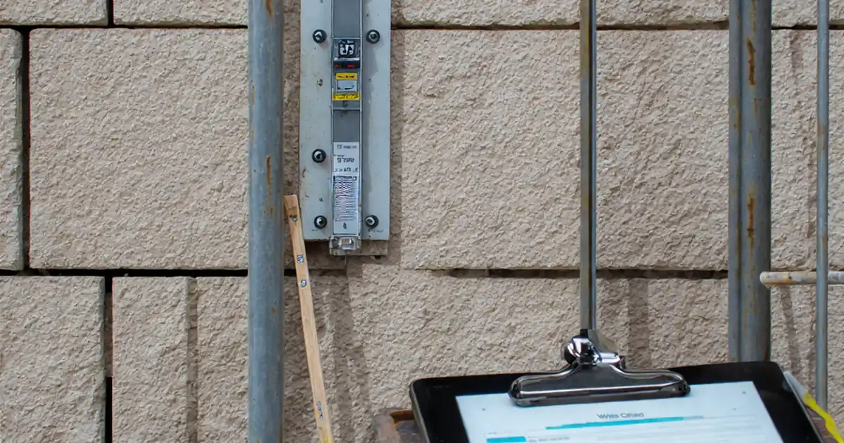
- Feeler gauges verify nominal joint width at multiple points
- Lasers and strings expose drift across long panel runs
- Thermal gaps prevent binding during seasonal temperature swings
- Early coordination avoids small, non-compliant cut pieces
Survey transfer and subframe tolerances underpin clean modules
Joint control begins with reliable survey transfer. Use a total station from calibrated benchmarks to pin the façade grid, then strike durable control lines on the substrate. Check slab edges with a 2 m straightedge and record highs/lows; bracket stand-off must cover these deviations while leaving spare adjustment. Rails must be set plumb and level using laser and digital levels; even 2–3 mm rail twist can telegraph into visible joint steps. Torque fixings per manufacturer data to prevent creep. Example: a bowed slab edge was corrected by mixing bracket sizes and using packers, preserving 12 mm nominal joints throughout. Record all readings, and note where adjustability is consumed; if little remains, escalate before installing panels. These actions make panel modules drop into place, prevent cumulative joint drift, and reduce rework during final alignment.
- Total station ensures grid within ±3 mm over 30 m
- Leave spare bracket adjustment after leveling rails
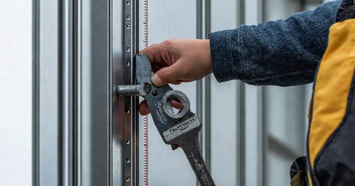
- Record torque values to prevent long-term relaxation
- Escalate when adjustability margin becomes inadequate
Interfaces, minimum cuts, and movement continuity
Modules must coordinate with windows, louvers, corners, and penetrations. Confirm as-built opening sizes before locking module widths; rebalance reveals to avoid narrow cut pieces that spoil appearance and complicate fixing. Maintain corner returns with matching joint lines on both faces, and check edge trims for consistent dimensions. Ensure cavities stay ventilated and that fire barriers align and seal the cavity as specified. Sealant joints, where required, need correct backer rod placement and depth per the manufacturer data sheet. One job learned that a planned 120 mm cut at a window jamb conflicted with fixing edge distances; the layout was adjusted to keep the minimum piece size within the approved limit, preserving both aesthetics and structural fixity. Thorough documentation—photos with scales, batch numbers, and marked-up drawings—supports fast approvals.
- Rebalance reveals to avoid sub-minimum cut pieces
- Mirror joint lines around corners for visual continuity
- Keep vents clear and fire barriers continuous
- Record batch numbers for traceable sealant works
How to Use This Interactive Joint & Module Coordination Checklist
- Preparation: Gather approved shop drawings, panel schedules, BIM views, survey benchmarks, manufacturer data sheets, and mock-up approvals. Bring a total station, laser level, 2 m straightedge, digital level, feeler gauges, torque wrench, steel tape, depth probe, PPE, and QR-enabled device.
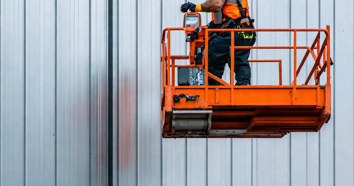
- Site readiness: Confirm access equipment is certified, work areas are clean and safe, and subframe works are available for inspection. Brief stakeholders on target tolerances and evidence requirements per approved project specifications and authority requirements.
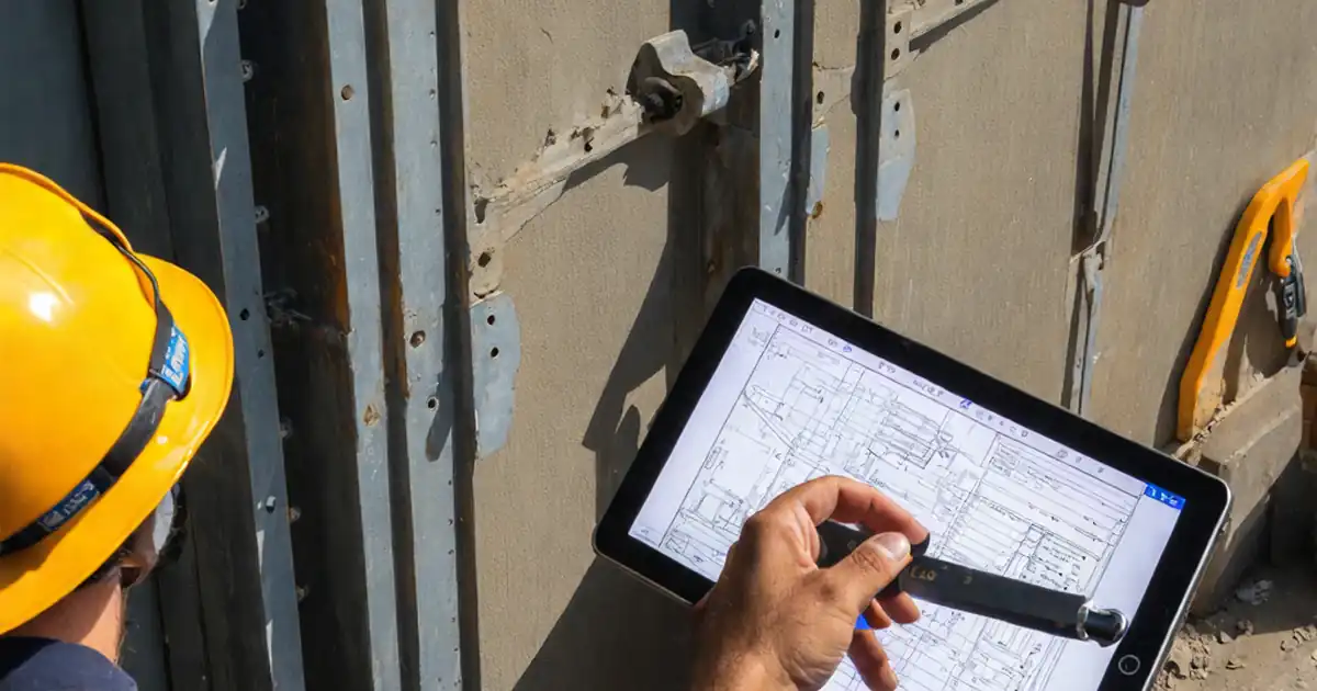
- Start interactive mode: Open the checklist, select location/elevation, and enable tick-and-comment. Scan or attach drawing revisions, panel IDs, and survey files so each item references current documents.
- Execute checks: Measure, photograph with scales, and record readings at the frequency defined in the items. Add comments for deviations, assign actions to responsible parties, and tag due dates.
- Coordinate and resolve: Use comments to agree on adjustments (e.g., re-shim rails, rebalance reveals). Upload updated mark-ups and obtain designer/quality approvals before proceeding to adjacent bays.
- Export and sign-off: Generate an export as PDF/Excel with embedded photos, measurements, and marked drawings. Apply digital signatures, distribute to stakeholders, archive to the project CDE, and store the QR-authenticated record.
Call to Action
- Start Checklist Tick off tasks, leave comments on items or the whole form, and export your completed report to PDF or Excel—with a built-in QR code for authenticity.
- Download Excel - Façade Aluminum Cladding Joint & Module Review
- Download PDF - Façade Aluminum Cladding Joint & Module Review
- View Image - Façade Aluminum Cladding Joint & Module Review
Cite & Embed
“Façade Aluminum Cladding Joint & Module Review by Quollnet”
with a link to
this source page.

FAQ
Question: What tolerances should I use for aluminum cladding joint widths and alignment?
Question: How do I prevent cumulative joint drift across a long elevation?
Question: When should module coordination be locked in relative to window openings?
Question: What evidence is most useful for sign-off on joint layout?
Related Articles
Broader reading and guidance connected to this checklist topic.

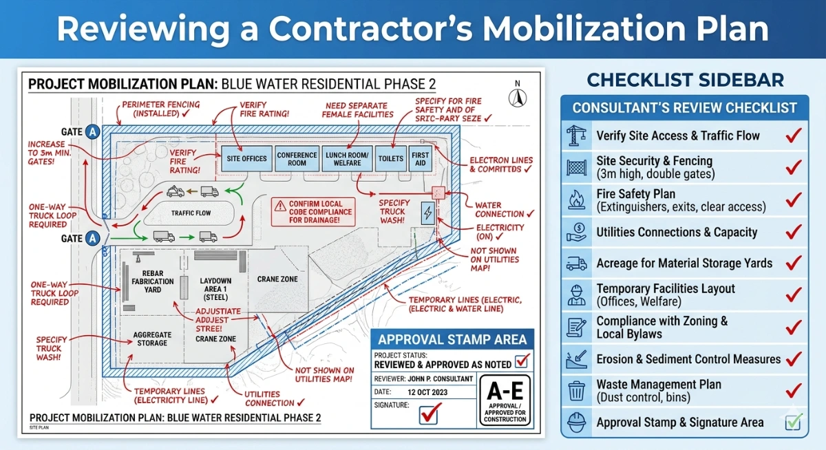
How To Review a Contractor’s Mobilization Plan

Improve Your Project Handover Process With Snag List Tracking App

Related Checklists
Keep the workflow moving with nearby templates chosen from similar checklist content.