Inspect aluminum cladding expansion joints and movement allowances
Definition: Inspect aluminum cladding expansion joints and movement allowances to verify joint sizing, compatible materials, and free movement paths for facade panels during thermal, seismic, and wind actions, aimed at site engineers and QA inspectors.
- Verify joint sizing, materials, and clear movement paths against drawings.
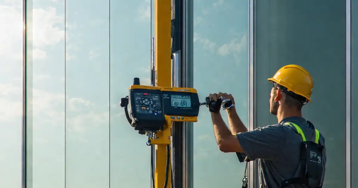
- Measure gaps, slots, and torque; document with photos and signatures.
- Prevent binding, leaks, and cracking through correct sealant/backer installation.
- Interactive, commentable, export to PDF/Excel; QR code for authenticated records.
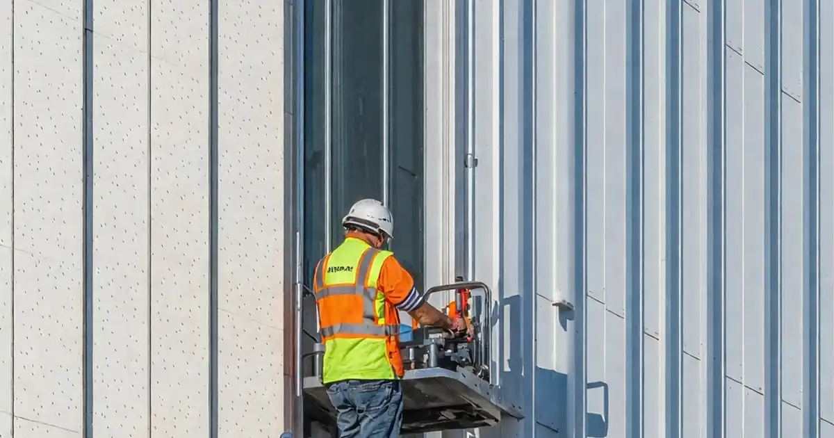
Inspect aluminum cladding expansion joints and movement allowances to ensure panels can safely accommodate thermal movement, wind-induced cycling, and building drift without binding or leakage. This checklist focuses on aluminum facade joints only, covering expansion gaps, joint sealants, backer rods, sliding fixings, and cover plates. By validating joint geometry, materials compatibility, and uninterrupted movement paths, you prevent stress transfer, panel distortion, sealant failure, and water ingress. The process aligns field conditions with approved project specifications and authority requirements through measurements, photos, and sign‑offs. You will verify subframe fixed/sliding points, slot lengths, isolation from dissimilar metals, sealant aspect ratio, and hose testing where appropriate. Acceptance cues include uniform gaps, correct fastener torque, verified sealant cure, and obstruction‑free cavities. The outcome is durable weatherproofing, preserved finishes, and reduced maintenance claims. Start in interactive mode to tick items, add comments for deviations, and export PDF/Excel with a QR code for authenticated records.
- This checklist verifies that aluminum cladding joints have the geometry, materials, and unobstructed movement paths required to absorb thermal expansion and structural drift. It reduces risks of panel buckling, sealant cracking, rattling noises, and rain penetration by aligning site conditions with approved drawings and product data.
- Interactive online checklist with tick, comment, and export features secured by QR code. The workflow captures measurements, photos, batch details, and sign‑offs, producing a traceable, shareable report that supports approvals, warranty packages, and maintenance handover without duplicating documentation effort.
- Actionable field steps specify tools, tolerances, and evidence such as torque logs, caliper readings, hose‑test photos, and primer records. Practical acceptance cues help crews correct issues early, keeping installation sequences on track and preventing costly rework at facade edges, corners, and movement interfaces.
Design and Documentation Verification
Materials and Components
Subframe and Fixings
Joint Geometry and Backing
Sealant, Covers, and Accessories
Design intent, movement calculations, and joint continuity
Successful aluminum cladding joints begin with confirming design intent: joint locations, target widths, and movement allowances must reflect thermal movement, wind cycling, and building drift. Review shop drawings and calculations to ensure the aluminum expansion coefficient and the project’s temperature range deliver adequate clearance at every joint. Check that movement is continuous through adjacent components like membranes, flashings, and fire barriers so no element unintentionally restrains the cladding. Where sealants are specified, verify movement capability and compatibility with anodized or powder‑coated finishes. Ensure the subframe strategy distinguishes between one fixed point and multiple sliding points to prevent panel creep. In practice, projects fail when slot lengths are undersized or cover plates are hard‑fixed, causing buckling and cracked sealant after a hot‑cold cycle. Establish documentation early: approved drawings, product data, and calculation sheets must be available on site and acknowledged by the installation team.
- One fixed point per panel; others must permit sliding.
- Joint width equals or exceeds design at ambient temperature.
- Movement continuity through membranes and flashings is documented.
- Sealant movement capability meets or exceeds design movement.
- All records traceable to drawing revisions and dates.
Subframe detailing, slots, and isolation for free movement
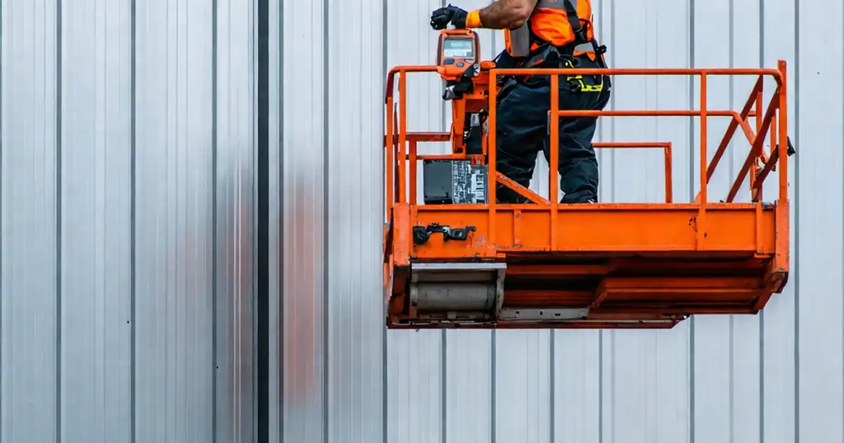
On site, precise subframe execution enables predictable movement. Verify orientation and length of bracket or rail slots allow travel parallel to the joint. Use calipers to confirm lengths exceed required movement by a contingency margin, and apply a calibrated torque wrench so fasteners clamp without pinching slots. Isolation pads or films must separate aluminum from dissimilar metals to limit galvanic action while preserving slip. Distinguish and mark fixed points to avoid installers inadvertently locking a sliding connector. In cavities, ensure no foam, mortar, or debris impedes panel travel. A common field correction is replacing round holes with slotted washers where drawings intended slots; this must be addressed with approved hardware, not ad‑hoc grinding. Maintain clear evidence: torque logs, slot measurements, and isolation photos keep the team aligned and prevent disputes at handover.
- Measure slot length and orientation with calipers.
- Use calibrated torque wrenches; record readings and tools.
- Install continuous isolators between dissimilar metals.
- Keep cavities clean; no debris or foam bridging joints.
Joint backing, sealant application, and performance checks
Proper backing and sealant geometry protect movement and weatherproofing. Select closed‑cell backer rod sized 25–50% above joint width for a controlled 2:1 sealant aspect ratio and two‑sided adhesion. Clean faces with approved solvent and apply primer where the data sheet requires, observing flash‑off times. Tool the sealant to a smooth concave profile, then verify tack‑free and cure times before exposure to water. If cover plates are specified, ensure slotted fixings and low‑friction interfaces permit slip under hand pressure. A low‑pressure hose test verifies water tightness without forcing water into unintended paths. Document ambient temperatures during installation and confirm installed widths reflect expected seasonal movement. This approach prevents three‑sided bonding, adhesive failure, and early cracking—common causes of callbacks after temperature swings and storms.
- Backer rod sized 25–50% over joint width.
- Target 2:1 sealant width‑to‑depth ratio.
- Primer applied and flashed per data sheet.
- Hose test confirms no leakage behind weatherline.
- Record ambient temperature during installation.
How to Use This Interactive Checklist
- Preparation: Gather approved drawings, calculation sheets, product data, calipers, feeler gauges, torque wrench, depth gauge, borescope, hose, thermometer, PPE, and cleaning/priming materials.
- Open the checklist on a tablet or phone; switch to interactive mode and select the project, elevation, and joint run you’re inspecting.
- Work item by item, entering measurements and attaching photos or short videos. Use comments to flag deviations or RFIs with locations.
- Tag responsible parties on comments for quick resolution, and log approvals or concessions per approved project specifications and authority requirements.
- Run a quick review to confirm all required fields are complete, including torque logs, batch numbers, temperatures, and test outcomes.
- Export the checklist as PDF/Excel for submittals. The export includes embedded photos, measurement tables, and a QR code for verification.
- Sign‑off: Capture digital signatures from the inspector, installer, and supervisor. Distribute and archive the authenticated report for project records.
Call to Action
- Start Checklist Tick off tasks, leave comments on items or the whole form, and export your completed report to PDF or Excel—with a built-in QR code for authenticity.
- Download Excel - Aluminum Cladding Expansion Joint Inspection
- Download PDF - Aluminum Cladding Expansion Joint Inspection
- View Image - Aluminum Cladding Expansion Joint Inspection
Cite & Embed
“Aluminum Cladding Expansion Joint Inspection by Quollnet”
with a link to
this source page.

FAQ
Question: How wide should aluminum cladding expansion joints be on site?
Question: Do I need a backer rod, and what size should it be?
Question: How do I confirm sliding connections are not locked?
Question: When should I perform a water test on joints?
Related Articles
Broader reading and guidance connected to this checklist topic.


Is It Important To Customize Your Qr Code And How To Do It?

Master Construction Project Cashflow With Cashflowpot

Related Checklists
Keep the workflow moving with nearby templates chosen from similar checklist content.