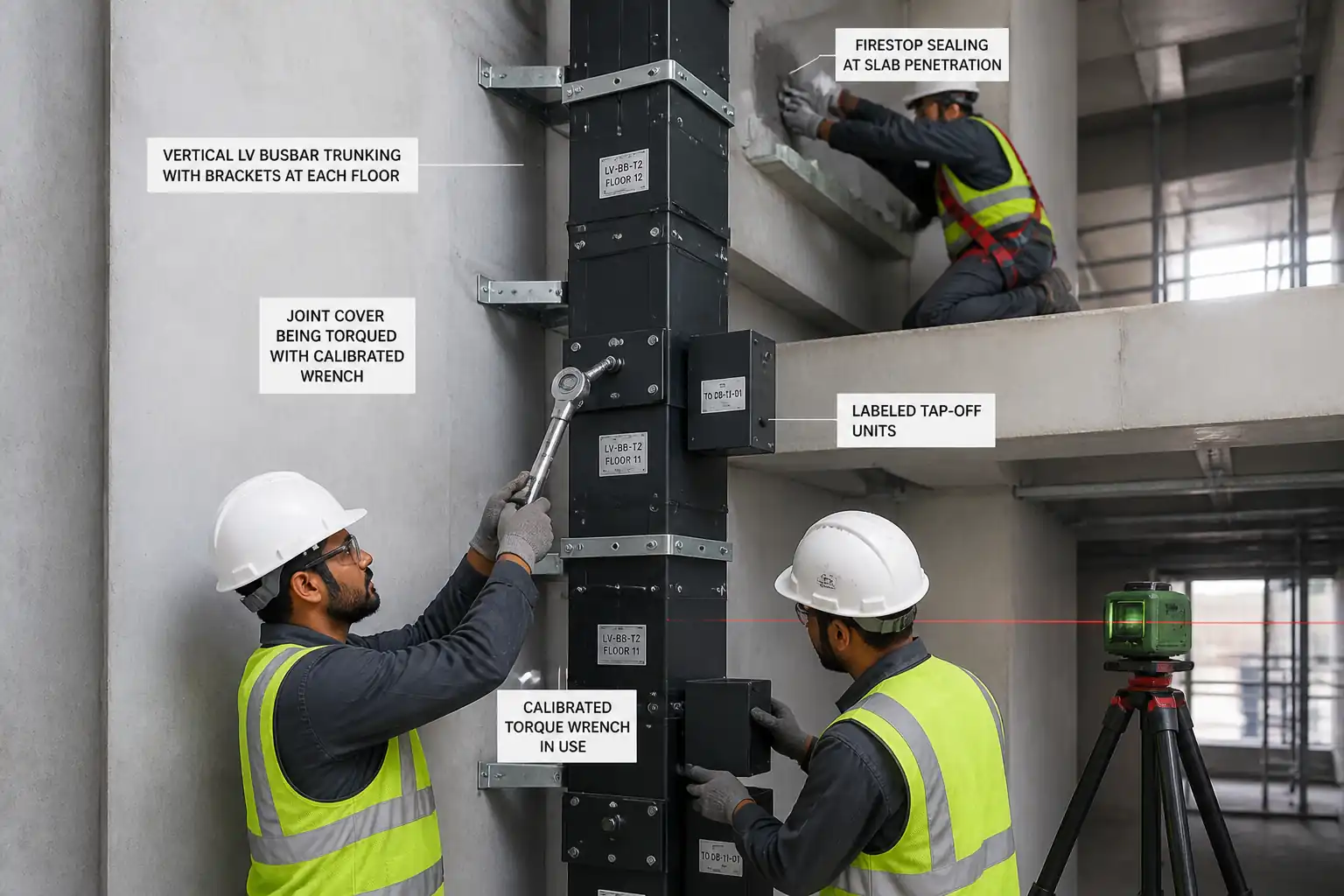

Inspection and Test Plan for Method Statement: Installation of Busbar Trunking System (Rising Mains) with Hangers, Joints, Tap-Off Units, Expansion Joints, and Fire Barriers; Pre-energization IR Test
AI-assisted inspection and test plan connected to a method statement, with PDF and Excel export.
More than a static template
Unlike a downloadable Word or PDF template, this ITP is an AI-assisted editable starting point directly connected to its method statement. Every inspection activity, hold point, and acceptance criterion is structured and ready to adapt to your project.
- AI-assisted customization — Tailor inspection activities and acceptance criteria to your specific project scope.
- Linked method statement — This ITP is connected to the corresponding method statement describing the work sequence.
- Multiple export formats — Download as a formatted PDF or editable Excel spreadsheet.
- Editable starting point, not a final document — Review and verify all content against your project specifications and standards before use.
What you can customize
When you save this ITP to your account, every inspection row becomes editable. You can add, remove, or modify:
- Inspection activity — Description of what is being inspected.
- Inspection type — Hold point (H), Witness point (W), Review (R), or Monitor (M).
- Responsibility — Contractor, subcontractor, engineer, or client.
- Frequency — How often the inspection occurs.
- Acceptance criteria — Referenced standard or specification requirement.
- Records — Forms, test reports, or checklists required as evidence.
Why this ITP is used
To ensure installation quality and compliance with standards and manufacturer requirements, controlling critical risks and performance prior to energization.
Who uses this inspection and test plan
Contractor’s QA/QC, Site Supervisors, Manufacturer’s reps, and the Engineer/Client for surveillance and approvals.
When this ITP is prepared and submitted
From material receipt through installation, testing, and documentation handover before energization.
Who receives or approves this ITP
Engineer/Client Representative
Inspection scope
Material verification, support and anchor installation, joint torqueing, expansion and tap-off installation, fire barriers, and electrical tests.
Typical hold, witness, and review points
HP-1: Joint torque verification; HP-2: Insulation resistance testing. Witness points include supports, expansion joints, tap-offs, firestopping, and final walkdown.
Typical inspection records
MIRs, torque logs, calibration certs, IR/continuity test sheets, anchor pull-test reports, firestop records, and as-built drawings.
Important approval note
This ITP is an AI-assisted editable starting point, not a pre-approved document. Before use on any project, all inspection activities, hold points, and acceptance criteria must be reviewed and approved by the relevant parties (superintendent, principal contractor, or client representative) in accordance with your contract and project quality plan.
Always verify acceptance criteria against your applicable drawings, specifications, and regulatory requirements. Hold points must be confirmed with the relevant authority before work proceeds past that point.
Inspection and test plan
| Activity | Inspection / Test | Acceptance Criteria | Responsibility | Record |
|---|---|---|---|---|
| Materials receipt (busbar, joints, supports, anchors, firestop) | Verify submittals, ratings, certificates | Conform to approvals; no damage; certificates present | QA/QC, Engineer (Surv.) | MIR, photos |
| Setting out and clearances | Dimensional survey | Centerline and plumb/level within tolerance; clearances per OEM [Verify] | Site Engineer/QAQC | Setout record |
| Support/hanger installation and anchors | Anchor installation checks; sample pull test | Spacing/support rating per design; anchors per ETA; pull tests pass [Verify] | Supervisor/QAQC/Engineer | Support checklist; pull-test report |
| Joint assembly and torqueing | Torque verification with calibrated wrench | All bolts within OEM torque range; covers fitted | Supervisor/QAQC/Engineer | Torque logs; calibration certs; photos |
| Expansion joint installation | Preset gap vs ambient; restraints free | OEM requirements achieved; identification label present | Supervisor/QAQC/Engineer | Checklist; photos |
| Tap-off units installation | Rating/compatibility; interlock check; terminal torque | Correct rating; mechanical/electrical fit; torque per OEM | Supervisor/QAQC | Tap-off checklist |
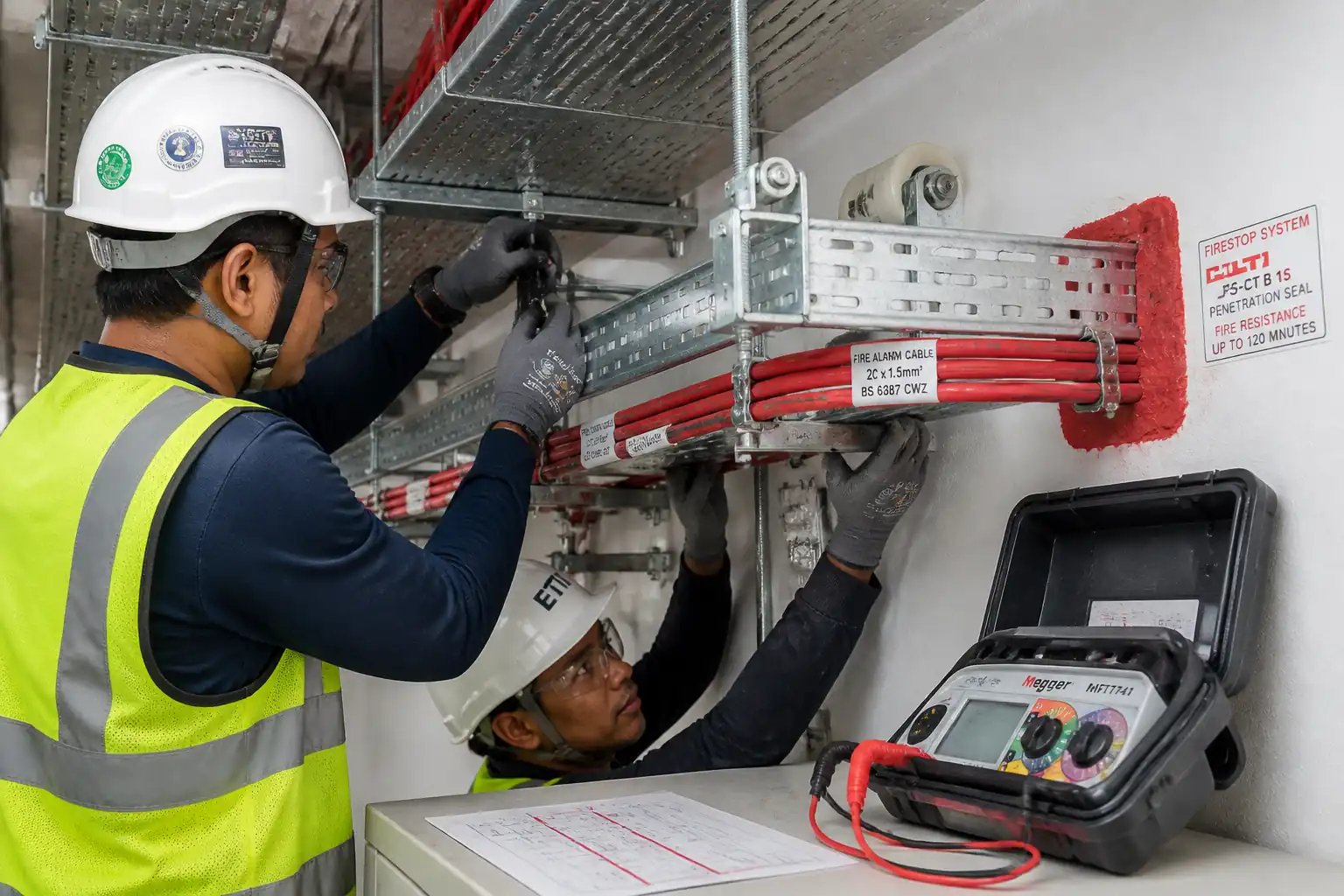
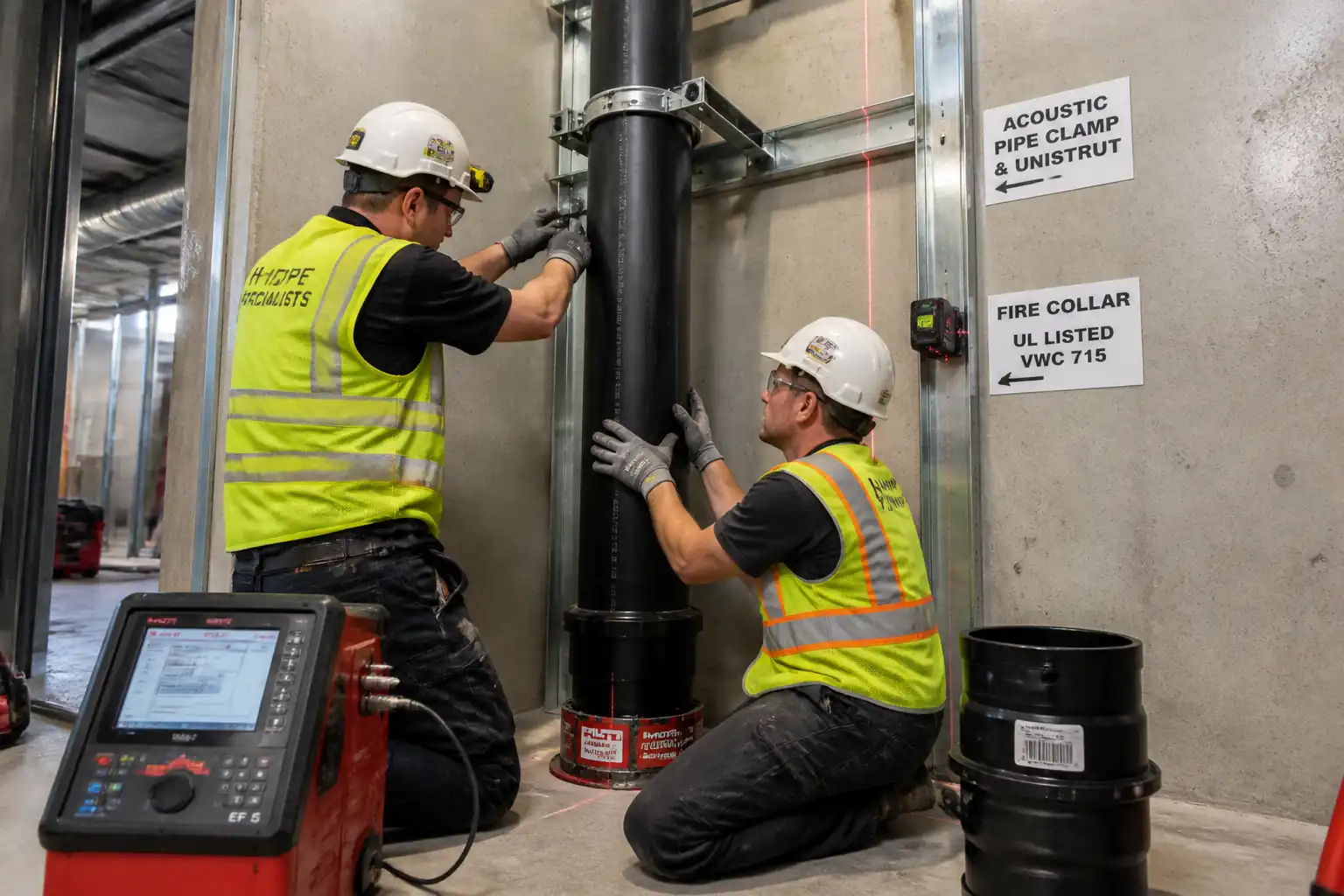
| Fire/smoke sealing at penetrations | Visual vs listing; thickness/depth; ID label | Matches FRL/REI; workmanship acceptable | Firestop Specialist/QAQC/Engineer | Firestop report; certs; photos |
| Pre-test verification | Covers on; LOTO; safe to test | Safe state confirmed; sign-offs in place | Supervisor/QAQC | Pre-test checklist |
| Insulation Resistance (IR) test pre-energization | IR at 1000 V DC for 1 min, ph-ph and ph-earth | ≥ 1 MΩ minimum; target ≥ 100 MΩ new [Verify per OEM/Project] | QAQC/Engineer | IR test sheets; instrument calibration |
| Continuity and phase rotation | Ohmmeter continuity; rotation meter | Continuity closed; correct sequence | QAQC/Supervisor | Test records |
| Final walkdown and documentation | Checklist and dossier review | All actions closed; documents complete | QAQC/Engineer | Signed ITP, handover dossier |
This table is a read-only public reference. Download the PDF or Excel version, or customize this ITP to edit it for your project.
Frequently asked questions
Related method statement
This Inspection and Test Plan is associated with the Method Statement: Installation of Busbar Trunking System (Rising Mains) with Hangers, Joints, Tap-Off Units, Expansion Joints, and Fire Barriers; Pre-energization IR Test method statement, which describes the step-by-step construction sequence, resources, materials, equipment, safety controls, and environmental controls for this activity.
View the Method Statement: Installation of Busbar Trunking System (Rising Mains) with Hangers, Joints, Tap-Off Units, Expansion Joints, and Fire Barriers; Pre-energization IR Test method statement →Continue with related inspection, method statement, article, and checklist resources.