
Method Statement: Field Joint Coating for Oil & Gas Pipelines – Method Statement
AI-assisted method statement with matching ITP, PDF download, and Excel export.
More than a static template
Unlike a downloadable Word or PDF template, this method statement is an AI-assisted editable starting point connected directly to a matching Inspection and Test Plan. Every section is structured, project-adaptable, and ready to export.
- AI-assisted drafting — Customize every section with AI for your specific project scope.
- Linked ITP — A matching inspection and test plan is generated alongside the method statement.
- Multiple export formats — Download as a formatted PDF or editable Excel spreadsheet.
- Editable starting point, not a final document — Review, verify, and adjust all content against your project requirements before use.
Static template vs. Quollnet workflow
| Feature | Static template | Quollnet |
|---|---|---|
| Project-specific content | Manual fill-in required | AI-assisted customization |
| Linked ITP | Separate document, no link | Matching ITP included |
| Export formats | Usually PDF only | PDF and Excel |
| Structured sections | Free-form layout | 13 standardized sections |
| Saved to your account | Local file only | Cloud-saved, reusable |
| Content accuracy | You verify everything | AI-assisted, you still verify |
| Cost | Often free but time-intensive | Free to customize and download |
What you can customize
When you save this method statement to your account, every section becomes editable. The following 13 sections are included:
- Scope — Defines the activity and its boundaries.
- References — Standards, specifications, and drawings.
- Responsibilities — Roles and accountabilities.
- Resources — Labour, plant, and equipment summary.
- Materials — Materials and compliance requirements.
- Equipment — Tools and equipment details.
- Prerequisites — Hold points and pre-conditions.
- Method sequence — Step-by-step construction sequence.
- Safety controls — HSE risk controls and PPE.
- Environmental controls — Environmental mitigation measures.
- QA/QC — Quality inspection and test requirements.
- ITP — Inspection and Test Plan table (has its own page).
- Attachments — Referenced drawings and documentation.
Why this method statement is used
This method statement is used to define and communicate the approved procedure for carrying out method statement: field joint coating for oil & gas pipelines on site. It ensures the work is planned in advance, the correct resources and controls are in place, and all personnel understand responsibilities, sequence, quality requirements, and safety controls before work begins. It aligns site execution with the documented scope and acceptance expectations.
Who uses this method statement
This method statement is used by contractors, site supervisors, project engineers, QA/QC engineers, HSE officers, consultants, and client representatives. It serves as a shared reference for planning, execution, supervision, inspection, and approval of the activity on site.
When it is prepared and submitted
The method statement is prepared before the work activity starts and submitted as part of the pre-construction documentation package for review and approval.
Who reviews or approves it
The method statement is usually submitted to the client representative, consultant, resident engineer, or project management consultant for review and approval before the work commences.
Important approval note
This method statement is an AI-assisted editable starting point, not a pre-approved document. Before use on any project, all content must be reviewed and approved by the relevant parties (superintendent, principal contractor, or client representative) in accordance with your contract and project quality plan.
For example: if your specification requires a departure from a referenced standard, that departure must be documented and approved separately — this method statement will not capture that automatically. Always verify against your applicable drawings, specifications, and regulatory requirements.
Method statement content
Scope
Overview
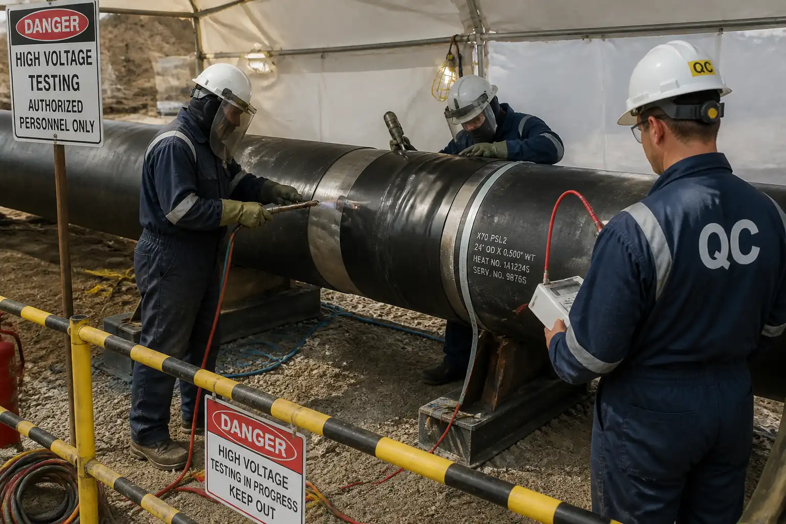
This method statement defines the procedures and controls for Field Joint Coating (FJC) of oil and gas pipelines after welding and NDE acceptance. It covers surface preparation, preheating, coating application for typical FJC systems (Fusion-Bonded Epoxy [FBE] powder, two-component liquid epoxy/polyurethane [PU], and heat-shrink sleeve [HSS] systems), curing, dry film thickness (DFT) checks, adhesion testing, holiday detection, repair procedures, environmental controls, QA/QC hold points, documentation, and final acceptance.
Pipeline and Coating Context
- Pipe Material: Carbon steel line pipe [Verify per project specifications].
- Factory-Applied Coating: Typically FBE, 3LPE, or 3LPP [Verify per project specifications].
- Field Joint Area: Bare steel weld area including overlap onto adjacent factory coating (cutback zones) per project and manufacturer’s data sheet (MDS).
Objective
- Restore continuous, defect-free, electrically holiday-free, and adherent external corrosion protection at each field weld joint to equivalent performance levels as the adjacent coating system, in accordance with ISO 21809-3 and project specifications.
Exclusions
- Internal coatings, in-ditch field repairs unrelated to joints, and cathodic protection installation are excluded from this method.
References
| Document Type | Reference / Number | Revision | Notes |
|---|---|---|---|
| ISO 21809-3: Petroleum and natural gas industries — External coatings for buried or submerged pipelines — Field joint coatings | |||
| ISO 8501-1 (Surface cleanliness visual grades, Sa 2½) | |||
| ISO 8502-3/4/6/9 (Dust test, dew point determination, and soluble salts by Bresle method) | |||
| ISO 8503-1/-2/-4/-5 (Surface profile comparators and replica tape) | |||
| ISO 2808 / ASTM D7091 / SSPC-PA 2 (Coating thickness measurement) [Verify per project specifications] | |||
| ASTM D4541 / ISO 4624 (Pull-off adhesion) [As applicable to liquid epoxy/PU] | |||
| NACE SP0274 / ASTM G62 (High-voltage holiday detection of pipeline coatings) | |||
| ISO 8504 (Surface preparation methods) | |||
| Manufacturer Data Sheets (MDS) and Safety Data Sheets (SDS) for all coating systems | MDS requirements take precedence where more restrictive | ||
| Project Specifications, Drawings, and Approved ITP | [Verify per project specifications] |
Responsibilities
| Role | Responsibility | Name / Party |
|---|---|---|
| Project Manager | Project Manager | Contractor |
| Site Engineer | Site Engineer | Contractor |
| Coating Supervisor | Coating Supervisor (NACE/FROSIO certified) | Contractor |
| HSE Officer | HSE Officer | Contractor |
| QC Inspector | QC Inspector (Coating) | Contractor |
| Client/TPI | Client/Engineer / Third-Party Inspector (TPI) | Client/TPI |
| Technicians | Blasting & Coating Crew | Contractor |
| Coordinator | Permit/Survey Coordinator | Contractor |
Resources
| Resource Type | Description | Quantity | Remarks |
|---|---|---|---|
| Person | Coating Supervisor (NACE/FROSIO) | 1 | |
| Person | QC Inspector (Coating) | 1 | |
| Persons | Blasters/Preppers | 2-4 | |
| Persons | Coating Applicators (Epoxy/PU or FBE) | 2-4 | |
| Persons | Helpers/Riggers | 2 | |
| Person | HSE Officer | 1 |
Materials
| Material | Specification / Grade | Quantity | Remarks |
|---|---|---|---|
| Liquid Epoxy/PU Coating | MDS: mix ratio, pot life, cure; Shelf life; Storage 5–35°C [Verify] | Typical DFT 400–1000 µm [Verify per project specifications] | |
| Fusion-Bonded Epoxy Powder | ISO 21809-2/-3 compliant; particle size & gel time per MDS | Target DFT 400–800 µm [Verify] | |
| HSS with primer/adhesive | ISO 21809-3 compliant; compatible with 3LPE/3LPP systems | Minimum overlap onto parent coating ≥100 mm each side [Verify] | |
| Liquid primer/adhesion promoter | Per coating vendor MDS | ||
| Epoxy repair stick/patch kit | Per MDS; cure at ambient or warm | ||
| Abrasive (garnet/steel grit) | ISO 11126/11127 (as applicable) | Grading to achieve 50–100 µm profile [Verify] | |
| Solvent wipes/cleaner | VOC compliant; SDS available | ||
| Masking tape, abrasive pads | Heat resistant to preheat temps |
Equipment
| Equipment | Capacity / Type | Quantity | Inspection Required |
|---|---|---|---|
| Air compressor + blast pot + nozzles | >7 m³/min [Verify] | ||
| Vacuum/dust collector | |||
| Replica tape & spring micrometer / Profilometer | |||
| Dew point meter, hygrometer, IR/contact thermometer | |||
| Bresle kit + conductivity meter | |||
| Induction heater with temp control | |||
| Propane torches & gas cylinders | |||
| Electrostatic powder spray unit | |||
| Plural component/hand mix tools, mixers, WFT combs | |||
| Heat-shrink sleeve rollers & temperature crayons | |||
| DFT gauge (electromagnetic) | Type 2 | ||
| Pull-off adhesion tester | |||
| High-voltage holiday detector (pulse) | 0–30 kV | ||
| Temporary enclosure/tent, barriers | |||
| Fire extinguishers, spill kits, drip trays |
Prerequisites
- Approved Method Statement, ITP, and relevant Work Packs.
- Welder NDE/NDT acceptance and released joint for coating; joint identification marked and traceable.
- Selected FJC system approved for compatibility with adjacent coating; vendor Technical Data Sheets (MDS) and SDS available.
- Equipment calibration certificates valid: DFT gauges, adhesion tester, holiday detector, dew point meter, IR thermometer.
- Ambient conditions forecast suitable: no rain, joint surface temperature ≥3°C above dew point; wind/dust controlled via enclosures as necessary. [Verify per project specifications]
- Permits: Hot Work, Confined Space (if bell hole), Excavation, and Energy Source control as applicable. [Verify per project HSE plan and local regulations]
- Materials inspected for shelf life, batch numbers, storage temperatures, and unopened condition; mixing/measuring tools clean.
- Mock-up/technique demonstration completed and accepted for each system prior to production.
- Adjacent factory coating edges inspected; cutback length and bevel free from undercut/disbondment; feathered/roughened 30–50 mm for overlap where required.
- Work area delineated with barriers; fire watch, extinguishers, and gas testing in place where required.
- Waste containers, abrasive recovery, and spill response set up.
Method Sequence
| Step | Activity | Description | Responsibility | Inspection / Hold Point |
|---|---|---|---|---|
| 1 | Joint release and identification | Confirm weld/NDE acceptance; verify joint ID; check cutback length per drawing (typical 150–300 mm each side) [Verify]. | Coating Supervisor / QC | Visual |
| 2 | Initial cleaning | Degrease/solvent clean joint and adjacent coating; remove soil, oil, moisture. | Blasting Crew | Visual |
| 3 | Environmental verification | Measure ambient T, RH, steel temperature, dew point; install wind/dust shields if needed. | QC | Measurement |
| 4 | Masking/edge prep | Feather and abrade adjacent coating edges 30–50 mm; apply masking as needed to protect. | Applicators | Visual/tactile |
| 5 | Abrasive blasting | Blast joint to ISO 8501-1 Sa 2½. Achieve anchor profile 50–100 µm [Verify]. Use clean, dry compressed air. | Blasting Crew | Visual & profile |
| 6 | Post-blast cleanliness | Check dust (ISO 8502-3) and soluble salts (Bresle ISO 8502-6/-9) at representative points. | QC | Testing |
| 7 | Preheating | Preheat joint and adjacent coating per selected system: FBE 230–250°C; Liquid epoxy/PU 60–80°C; HSS 80–120°C at overlap areas. Use calibrated IR/contact thermometer. | Applicators | Measurement |
| 8A | Apply FBE powder (if specified) | Heat to target; apply electrostatic FBE uniformly; build to DFT 400–800 µm; overlap onto adjacent FBE; allow gel/cure per MDS. Avoid quenching unless permitted. | Applicators | Process control |
| 8B | Apply liquid epoxy/PU (if specified) | Mix per MDS; verify pot life; apply stripe coat at edges; apply WFT to achieve DFT 400–1000 µm; multiple coats if required within recoat window. | Applicators | Process control |
| 8C | Install heat-shrink sleeve (if specified) | Apply primer/adhesion promoter if required; center sleeve; pre-shrink tack; shrink from center outward with controlled heat; roll to expel air; install closure patch. Overlap onto parent coating ≥100 mm each side [Verify]. | Applicators | Visual/temperature |
| 9 | Curing/cool down | Allow coating to cure/cool per MDS before handling or testing. Verify hardness if specified. | Coating Supervisor | Time/temperature |
| 10 | DFT measurement | Measure DFT with calibrated gauge at min 5 locations around joint (e.g., 12, 2, 4, 8, 10 o’clock), 3 readings per location; compute averages per SSPC-PA 2/ISO 2808. | QC | Thickness |
| 11 | Adhesion testing (sampling) | Perform pull-off adhesion on frequency basis (e.g., 1 per 50 joints per crew or per day). Prepare dollies per ASTM D4541; repair test areas after. | QC | Adhesion |
| 12 | Holiday detection | 100% high-voltage holiday detection after cure/cool. Set voltage to coating type and DFT per NACE SP0274/ASTM G62; typical 2.5–5.0 kV for 0.4–1.0 mm epoxy [Verify]. Scan speed ≈0.3 m/s. | QC | Holiday test |
| 13 | Repairs | Identify defects; abrade and clean surrounding 30–50 mm; apply approved repair compound/patch; allow cure; re-check DFT and holiday. | Applicators / QC | Visual/holiday |
| 14 | Final acceptance & documentation | Complete records: materials/batches, environmental logs, DFT, adhesion (if any), holiday, repairs. Obtain Client/TPI release. | QC / TPI | Document review |
| 15 | Handling and lowering-in | Use padded slings; avoid point loads; protect coated joints; perform post-lowering holiday check where specified. | Construction / QC | Visual/holiday |
| 16 | Demobilization & housekeeping | Remove waste, recover abrasive, segregate hazardous materials, return instruments, close permits. | Coating Supervisor / HSE | Site inspection |
Safety Controls
Task-specific HSE Controls
- Hazard: Abrasive blasting (airborne dust, ricochet)
- Consequence: Eye injury, respiratory illness, skin abrasion.
- Engineering/Procedural Control: Use low-silica abrasive; blast nozzles with deadman control; blast curtains/enclosures; compressed air with moisture separators; exclusion zone with signage.
- Required PPE: Blast hood with Grade D breathable air, gloves, blast suit, steel-toe boots, hearing protection.
- Collective Measure: Physical barricades and spotter to control access.
-
Inspection/Permit: Inspect hoses/nozzles daily; record compressor dew-point; permit to work where required.
-
Hazard: Hot work from propane torches/closure patch heating
- Consequence: Burns, fire/explosion.
- Engineering/Procedural Control: Hot Work Permit; check and fit flashback arrestors; leak-test hoses; maintain minimum 15 m hot work radius clearance or shielding; fire watch with extinguishers.
- PPE: Heat-resistant gloves, face shield, FR clothing, safety glasses.
- Collective Measure: Fire blankets/spark containment; gas cylinder stands and segregation.
-
Inspection/Permit: Hot Work Permit; gas detector if in bell hole/low area; extinguisher inspection tags current. [Verify per project HSE plan and local regulations]
-
Hazard: Induction heating/high surface temperatures (FBE)
- Consequence: Severe burns, equipment fire.
- Engineering/Procedural Control: Temperature interlocks; no flammable materials within clearance; tools rated for high temp; thermal crayons for verification.
- PPE: Heat-resistant gloves, long sleeves, face shield.
- Collective Measure: Mark hot zones; restrict access during heating.
-
Inspection/Permit: Pre-use inspection; calibration of thermometers; equipment operator certification.
-
Hazard: Chemical exposure to epoxy/PU (amines/isocyanates)
- Consequence: Dermatitis, respiratory sensitization, eye injury.
- Engineering/Procedural Control: Use mixing stations with ventilation; closed containers; follow SDS; prohibit food/drink in area; implement isocyanate controls if PU used (air monitoring, medical surveillance as required).
- PPE: Chemical-resistant gloves (nitrile), goggles/face shield, coveralls; respirator with A2/P3 filters or air-fed where ventilation is insufficient.
- Collective Measure: Local exhaust ventilation; spill kits and neutralizers.
-
Inspection/Permit: SDS availability; COSHH/chemical handling permit if applicable; fit-testing and respirator inspection records.
-
Hazard: High-voltage holiday testing
- Consequence: Electric shock, burns.
- Engineering/Procedural Control: Only trained operators; ensure equipment grounding; set voltage per DFT; maintain dry conditions; warning signs during testing.
- PPE: Electrically insulating gloves, dry boots, safety glasses.
- Collective Measure: Exclusion zone during testing.
-
Inspection/Permit: Daily function test; calibration certificate; toolbox talk on shock hazards.
-
Hazard: Work at trench edges/bell holes and uneven terrain
- Consequence: Falls, entrapment, struck-by.
- Engineering/Procedural Control: Maintain trench boxes/shoring per excavation plan; safe access/egress; use platforms for joint access; housekeeping to prevent slips.
- PPE: Hard hat, high-vis, safety boots, gloves.
- Collective Measure: Edge protection, barriers, banksman for plant movements.
-
Inspection/Permit: Excavation permit; daily pre-shift trench inspection.
-
Hazard: Manual handling/rolling pipes and sleeves
- Consequence: Musculoskeletal injury, pinch points.
- Engineering/Procedural Control: Use pipe stands/rollers; team lifts; mechanical aids.
- PPE: Cut-resistant gloves, safety boots.
- Collective Measure: Hands-free tools; pinch-point awareness briefed.
-
Inspection/Permit: Manual handling assessment.
-
Hazard: Noise from compressors and blasting
- Consequence: Hearing loss.
- Engineering/Procedural Control: Distance and acoustic screens; maintenance of silencers.
- PPE: Ear plugs/muffs meeting SNR/NRR.
- Collective Measure: Noise map signage.
-
Inspection/Permit: Noise monitoring as required.
-
Hazard: Heat stress/cold stress during preheating or adverse weather
- Consequence: Heat exhaustion, hypothermia.
- Engineering/Procedural Control: Work/rest cycles; hydration; shaded rest areas; weather monitoring.
- PPE: Weather-appropriate PPE; cooling vests if needed.
- Collective Measure: Supervisor monitoring for symptoms.
- Inspection/Permit: HSE plan provisions; first aid availability.
Environmental Controls
- Abrasive containment: Use shrouds and ground tarps to capture spent abrasive; recover and dispose per waste code. Wet down surrounding area if dust risk and compatible with process.
- Spent abrasive and coating waste: Segregate as potentially hazardous; store in sealed, labeled containers; manifest to licensed disposal.
- VOC/odour control: Prefer solvent-free systems; keep containers closed; use local ventilation in enclosures; avoid application during inversion conditions.
- Solvent and chemical storage: Bunded area, away from watercourses; SDS on site; spill kits within 15 m; drip trays under mixing stations.
- Noise: Position compressors away from receptors; use acoustic barriers where needed; restrict high-noise to agreed hours.
- Soil and water protection: No blasting or solvent use within exclusion buffer of water bodies unless additional controls approved; prevent runoff; do not wash tools into soil; manage rinse water as waste.
- Waste records: Keep daily waste logs, quantities, disposal receipts.
- Wildlife and vegetation: Avoid damage beyond work limits; promptly clean accidental releases; reinstate any disturbed areas.
- Energy: Shut down idling equipment when not in use; routine maintenance to maintain efficiency.
- Compliance: Follow project Environmental Management System and local regulations. [Verify per project HSE plan and local regulations]
QA/QC
Quality Plan and Controls
- Qualifications: Coating Supervisor and QC Inspector to hold recognized certification (e.g., NACE/FROSIO). Applicators trained by system vendor.
- Calibration: DFT gauge, holiday detector, adhesion tester, thermometers, dew point meters—valid calibration certificates and daily function checks recorded.
- Materials control: Verify batch numbers, shelf life, storage temperatures (typ. 5–35°C) and unopened condition; record batch numbers used per joint.
- Environmental monitoring: Log ambient/steel temps, RH, dew point before surface prep and before coating; at least every 4 hours or change of conditions.
- Surface preparation: Verify Sa 2½ visually, surface profile (target 50–100 µm [Verify]), dust rating ≤2, soluble salts ≤20 mg/m² [Verify]. Hold point prior to coating.
- Application controls: Record preheat temperatures, WFT/DFT targets, pot life start/finish times, recoat intervals, shrink temperatures (HSS), and overlap dimensions.
- Thickness measurements: Minimum 5 locations per joint, 3 gauge readings per location. Acceptance per SSPC-PA 2/ISO 2808 and project min/max. Address any local low readings by repair.
- Adhesion testing: Frequency e.g., 1 per 50 joints per crew/day [Verify]. Acceptance typically ≥5 MPa cohesive failure for liquid epoxy/PU; HSS per vendor peel criteria. Repair and re-test if failing.
- Holiday testing: 100% of joints. Set voltage per standard/vendor tables according to DFT and coating type. Mark and repair all holidays, then re-test 100%.
- Documentation: FJC report for each joint including joint ID, date/time, crew, system, batch/lot, climate data, surface prep results, DFT, adhesion (if tested), holiday results, repairs, and signatures.
- Hold/Witness points: Post-blast inspection (Hold), DFT (Hold), Holiday test (Hold), Adhesion sampling (Witness), Final acceptance (Hold).
- Nonconformities: Log NCRs, implement corrective actions, and conduct re-inspection. Prevent recurrence via toolbox brief and method review.
- Records retention: As-built coating dossier retained per contract (min. 5–10 years) [Verify per project specifications].
Attachments
- Coating vendor MDS and SDS (FBE, liquid epoxy/PU, HSS systems)
- Approved ITP and Method Statement sign-off sheet
- Equipment calibration certificates (DFT gauge, holiday detector, adhesion tester, thermometers, dew point meters)
- Pre-start risk assessment/JSA and permits (Hot Work, Excavation, Confined Space as applicable)
- Training/competency records (NACE/FROSIO certificates, equipment operator authorizations)
- Daily FJC reports and logs (climate, preheat, WFT/DFT, adhesion, holiday, repairs)
- Waste disposal manifests and environmental logs
- As-built joint map with coating status
This content is a read-only public reference. Download or customize to get an editable version.
ITP preview
The first inspection activities from the linked ITP for Method Statement: Field Joint Coating for Oil & Gas Pipelines:
| Activity | Inspection / Test | Acceptance Criteria | Responsibility | Record |
|---|---|---|---|---|
| Pre-start documentation | Verify approved MS/ITP, MDS/SDS, calibration certs | All approvals current; instruments within calibration; materials approved | QC Inspector (Hold) / Client (Witness) | Pre-start checklist, approvals register |
| Joint release verification | Check NDE acceptance and joint ID | Joint released for coating; ID traceable | QC Inspector | Weld/NDE release, FJC log |
| Environmental conditions | Measure T/RH/steel temp/dew point (ISO 8502-4) | Steel ≥3°C above dew point; RH ≤85% [Verify] | QC Inspector | Climate log |
Showing 3 of 17 inspection activities. View full ITP →
Related Inspection and Test Plan
An Inspection and Test Plan (ITP) is available for Method Statement: Field Joint Coating for Oil & Gas Pipelines. The ITP defines the inspection activities, acceptance criteria, hold and witness points, responsible parties, and records required to verify the work described in this method statement.
View the Method Statement: Field Joint Coating for Oil & Gas Pipelines ITP →