Apply Corrosion Protection at Pile Heads – QA Checklist
Definition: Apply corrosion protection at pile heads for steel and concrete interfaces using specified coatings or cathodic connections, ensuring verified DFT, batch traceability, and exclusion of jackets for QA teams.
- Verify scope, materials, and methods per approved project specifications.
- Control surface prep, environment, and DFT for durable protection.
- Install cathodic interfaces with verified continuity and isolation.
- Interactive, commentable, export options with QR code verification.
Apply corrosion protection at pile heads is a focused quality-control activity covering pile head coating application and cathodic protection interface works where specified. This checklist addresses surface preparation, environmental controls, DFT verification, holiday testing, electrical continuity/isolations, and documentation of coating batch numbers. It applies to steel and concrete pile head interfaces adjacent to caps, plinths, or slabs, and expressly excludes pile jackets or encasement systems. By following these steps, teams reduce early coating failures, underfilm corrosion, and CP malfunction caused by poor bonding, moisture entrapment, or inadequate thickness. Outcomes include traceable coating lots, reproducible DFT measurements in micrometres, defect-free film via holiday detection, and proven CP terminations with secure torque values and low resistance paths where required. Use this interactive checklist to assign tasks, tick items, add field comments, attach photos and readings, and export to PDF/Excel with a QR for authentication.
- Ensure compliant corrosion protection at pile heads by controlling surface cleanliness, profile, ambient conditions, and dry film thickness. Achieve defect-free coatings and reliable cathodic interfaces while documenting batches, tools, and calibrated measurements for full traceability.
- Avoid premature coating failure and CP issues by verifying dew point separation, moisture-free substrates, stripe coats at edges, curing windows, and zero-holiday results. Capture photo evidence, meter readings, batch labels, and sign-offs at each stage.
- Confirm correct cathodic connections and isolations at the pile head, including verified torque, protected terminations, and continuity values within specified limits. Prevent inadvertent shorts to reinforcement and preserve designed electrical pathways.
- Interactive online checklist with tick, comment, and export features secured by QR code. Share records instantly with stakeholders and archive verified PDFs/Excels for closeout and authority submissions without rework.
Pre-Work Verification
Environmental and Surface Conditions
Surface Preparation
Coating Application and Curing
Cathodic Interface Installation
Inspection, Testing, and Documentation
Scope, Interfaces, and Exclusions
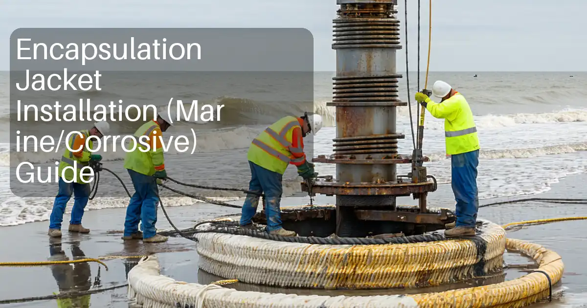
This checklist governs corrosion protection at pile heads where coatings and cathodic protection interfaces occur. It focuses on the immediate head zone at steel or concrete interfaces with caps or slabs. Tasks include environmental control, surface preparation, coating application, DFT verification, holiday testing, and cathodic connection termination or isolation work. Jackets or encasements are outside scope; confirm they are excluded before starting. Success relies on clear boundaries, correct masking at construction joints, and coordination with structural and electrical teams to avoid clashes. Field teams should align on acceptance thresholds per approved project specifications and authority requirements. Practical outcomes include a defect-free film in micrometres, proven electrical continuity where required, and traceable material records. The flow moves from verification to preparation, application, testing, and documentation—minimizing rework and ensuring durable protection in aggressive environments such as marine splash or de-icing exposure.
- Work only at pile heads and adjacent cap interfaces.
- Exclude jackets and encasement systems from this scope.
- Coordinate with CP, structural, and coatings teams.
- Define acceptance limits per approved specifications.
- Mask boundaries to maintain clean interface lines.
Surface Preparation and Coating Controls
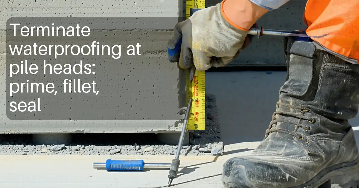
Durable protection starts with clean, profiled substrates and controlled ambient conditions. For steel, abrasive blasting to the specified cleanliness removes mill scale and rust; measure anchor profile with comparators or replica tape and record averages. For concrete, mechanically abrade to a sound surface, removing laitance and dust. Control moisture by verifying the substrate is at least 3 °C above dew point and salt contamination is within limits. Apply a stripe coat to edges and transitions, then full coats to the specified wet film thickness. Calibrate gauges, record WFT during application, and confirm DFT after cure using multiple readings. Respect recoat windows and minimum cure times to avoid intercoat adhesion failures. Conduct holiday testing on the finished film and repair any defects promptly before retesting. Label the completed system clearly for future maintenance reference.
- Maintain ≥ 3 °C dew point separation.
- Record WFT during application and DFT after cure.
- Stripe coat edges and discontinuities first.
- Repair and retest any holiday indications.
- Calibrated instruments with current certificates.
Cathodic Interface and Documentation
Where cathodic protection is specified, the pile head interface must provide reliable electrical performance and long-term durability. Prepare the contact surface to bright metal, install the correct lug or pad, and protect the termination with heat-shrink and mechanical guards. Verify fastener torque and measure resistance from lug to pile steel to confirm continuity; also confirm isolation from adjacent reinforcement when required, avoiding unintended shorts through concrete interfaces. After coating and CP works, compile a complete record pack: batch labels, product data sheets, calibration certificates, environmental logs, DFT and holiday test results, continuity readings, and photographs before, during, and after each operation. Finally, generate an exportable report with signatures, timestamps, and a QR code to authenticate the record for handover and future audits.
- Clean, bright-metal contact at CP pads.
- Record torque and continuity resistance.
- Protect terminations with heat-shrink/guards.
- Confirm isolation from reinforcement where required.
- Export signed pack with QR authentication.
How to Use This Interactive Pile Head Corrosion Protection Checklist
- Preparation: Assemble approved specifications, drawings, ITP, SDS, and data sheets. Gather tools: DFT gauge, WFT comb, thermo-hygrometer, dew point calculator, replica tape, holiday detector, torque wrench, multimeter, blasting/abrasion tools, masking, PPE.
- Open the checklist and select the work location and pile ID. Confirm that jackets are excluded and the correct coating/CP interface details apply to this pile head.
- Using the Interactive Checklist: Start interactive mode, tick each item as performed, and add time-stamped comments with photos of readings, batch labels, and surface condition evidence.
- Enter numerical measurements directly into fields (DFT in µm, dew point separation in °C, torque in N·m, resistance in Ω). Attach instrument calibration certificates.
- If an item fails, flag it, add a corrective-action comment, and assign it to the responsible party. Retest and document closure with new readings and photos.
- Export the completed record as PDF/Excel with embedded photos and measurement logs. Enable QR code to authenticate the exported file against the online record.
- Sign-Off: Obtain digital signatures from contractor, QC inspector, and client representative. Include date/time stamps and role titles.
- Archive: Store the signed checklist in the project document system and link it to the as-built record and maintenance plan for future reference.

Call to Action
- Start Checklist Tick off tasks, leave comments on items or the whole form, and export your completed report to PDF or Excel—with a built-in QR code for authenticity.
- Download Excel - Pile Head Corrosion Protection
- Download PDF - Pile Head Corrosion Protection
- View Image - Pile Head Corrosion Protection
Cite & Embed
“Pile Head Corrosion Protection by Quollnet”
with a link to
this source page.

FAQ
Question: What DFT should I target at the pile head and how many readings are required?
Question: How do I verify environmental conditions before coating the pile head?
Question: What tests confirm the cathodic interface is correctly installed?
Question: Why are jackets excluded from this checklist?
Question: What documentation is needed for closeout and audits?
Related Articles
Broader reading and guidance connected to this checklist topic.


Open Ncrs At Taking-over / Dlp: What Happens At Handover And How To Escalate

Is It Important To Customize Your Qr Code And How To Do It?


Terms Of Service – Quollnet By Quoll Lda
Related Checklists
Keep the workflow moving with nearby templates chosen from similar checklist content.