
Method Statement: Blind Lifting Operations into Deep Shafts or Building Interiors – Method Statement
AI-assisted method statement with matching ITP, PDF download, and Excel export.
More than a static template
Unlike a downloadable Word or PDF template, this method statement is an AI-assisted editable starting point connected directly to a matching Inspection and Test Plan. Every section is structured, project-adaptable, and ready to export.
- AI-assisted drafting — Customize every section with AI for your specific project scope.
- Linked ITP — A matching inspection and test plan is generated alongside the method statement.
- Multiple export formats — Download as a formatted PDF or editable Excel spreadsheet.
- Editable starting point, not a final document — Review, verify, and adjust all content against your project requirements before use.
Static template vs. Quollnet workflow
| Feature | Static template | Quollnet |
|---|---|---|
| Project-specific content | Manual fill-in required | AI-assisted customization |
| Linked ITP | Separate document, no link | Matching ITP included |
| Export formats | Usually PDF only | PDF and Excel |
| Structured sections | Free-form layout | 13 standardized sections |
| Saved to your account | Local file only | Cloud-saved, reusable |
| Content accuracy | You verify everything | AI-assisted, you still verify |
| Cost | Often free but time-intensive | Free to customize and download |
What you can customize
When you save this method statement to your account, every section becomes editable. The following 13 sections are included:
- Scope — Defines the activity and its boundaries.
- References — Standards, specifications, and drawings.
- Responsibilities — Roles and accountabilities.
- Resources — Labour, plant, and equipment summary.
- Materials — Materials and compliance requirements.
- Equipment — Tools and equipment details.
- Prerequisites — Hold points and pre-conditions.
- Method sequence — Step-by-step construction sequence.
- Safety controls — HSE risk controls and PPE.
- Environmental controls — Environmental mitigation measures.
- QA/QC — Quality inspection and test requirements.
- ITP — Inspection and Test Plan table (has its own page).
- Attachments — Referenced drawings and documentation.
Why this method statement is used
This method statement is used to define and communicate the approved procedure for carrying out method statement: blind lifting operations into deep shafts or building interiors on site. It ensures the work is planned in advance, the correct resources and controls are in place, and all personnel understand responsibilities, sequence, quality requirements, and safety controls before work begins. It aligns site execution with the documented scope and acceptance expectations.
Who uses this method statement
This method statement is used by contractors, site supervisors, project engineers, QA/QC engineers, HSE officers, consultants, and client representatives. It serves as a shared reference for planning, execution, supervision, inspection, and approval of the activity on site.
When it is prepared and submitted
The method statement is prepared before the work activity starts and submitted as part of the pre-construction documentation package for review and approval.
Who reviews or approves it
The method statement is usually submitted to the client representative, consultant, resident engineer, or project management consultant for review and approval before the work commences.
Important approval note
This method statement is an AI-assisted editable starting point, not a pre-approved document. Before use on any project, all content must be reviewed and approved by the relevant parties (superintendent, principal contractor, or client representative) in accordance with your contract and project quality plan.
For example: if your specification requires a departure from a referenced standard, that departure must be documented and approved separately — this method statement will not capture that automatically. Always verify against your applicable drawings, specifications, and regulatory requirements.
Method statement content
Scope
Purpose
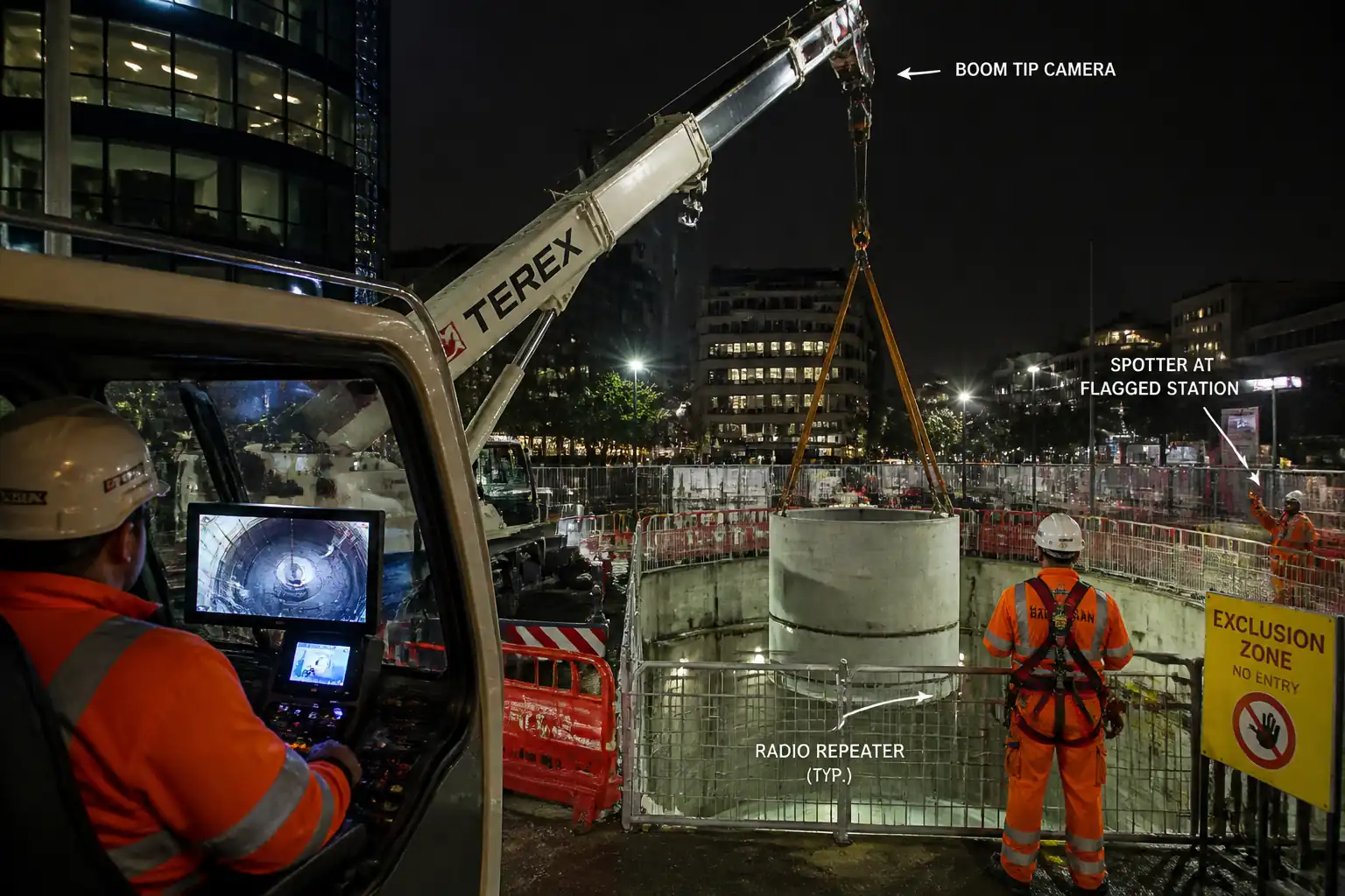
Provide a complete method to plan and execute blind lifting operations into deep shafts or building interiors where direct line-of-sight between crane operator and load is obstructed. Includes design and use of multi-stage radio signaling repeaters, crane boom-tip video camera installation and calibration, secondary spotter flag stations, tag line handling, and crane operator anti-collision monitoring.
Work Included
- Engineering lift planning, risk assessment, and permits.
- Crane setup, ground bearing arrangements, and exclusion zones.
- Rigging selection and inspection.
- Deployment and testing of multi-stage radio communication repeaters for signal relay into shafts/interiors.
- Installation and calibration of crane boom-tip video camera and operator cab monitor.
- Establishment of primary signaller and secondary spotter flag stations.
- Tag line preparation and handling rules for controlled rotation and orientation.
- Anti-collision system configuration and monitoring (A2B, LMI, virtual walls, zoning).
- Trial lift, controlled blind lift execution, landing, and de-rigging.
Out of Scope
- Structural modification of shafts or permanent works (to be provided by Temporary Works Designer where required).
- Electrical isolation/relocation of live services outside the lift zone.
Interfaces
- Temporary Works for shaft edge protection and lifting points [Verify per project specifications].
- Traffic management and logistics for delivery/egress.
- Confined space protocols if personnel enter shaft/interior [Verify per project HSE plan and local regulations].
References
| Document Type | Reference / Number | Revision | Notes |
|---|---|---|---|
| Standard | BS 7121-1 | ||
| Standard | BS 7121-3 | ||
| Standard | BS 7121-5 | ||
| Standard | ISO 12480-1 | ||
| Standard | ISO 9927 | ||
| Standard | ISO 4309 | ||
| Standard | ASME B30.5 | ||
| Standard | ASME B30.3 | ||
| Standard | ASME B30.9 / B30.26 | ||
| Standard | EN 13000+A1 | ||
| Regulation | OSHA 1926 Subpart CC | [Verify per jurisdiction] |
Responsibilities
| Role | Responsibility | Name / Party |
|---|---|---|
| Client Representative | Review/Approval | Client |
| PC/PM | Management | Principal Contractor |
| AP | Engineering and Planning | Contractor |
| Supervisor | Supervision | Contractor |
| Operator | Operation | Contractor/Subcontractor |
| Slinger/Signaller | Rigging/Signalling | Contractor |
| Spotter | Spotting/Relaying | Contractor |
| RF Technician | Comms Setup | Specialist Vendor/Contractor |
| Technician | Camera Setup | Specialist Vendor/Contractor |
| HSE | HSE Oversight | Principal Contractor |
| TWC/TWD | Engineering Approval | Principal Contractor/Designer |
Resources
| Resource Type | Description | Quantity | Remarks |
|---|---|---|---|
| Personnel | Engineering calculations, lift plan, ground bearing assessment | 1 | Competent per BS 7121 |
| Personnel | Site control, permits, briefings | 1 | |
| Personnel | Operate crane and safety systems | 1 | Certified |
| Personnel | Rigging, signalling, attach/detach loads | 2-4 | |
| Personnel | Visual relay and verification | 2 | |
| Personnel | Repeaters setup, testing, maintenance | 1 | |
| Personnel | Boom-tip camera system installation and calibration | 1 | |
| Personnel | Manage site access/egress | 1 | |
| Personnel | Immediate response | 1 | On shift |
Materials
| Material | Specification / Grade | Quantity | Remarks |
|---|---|---|---|
| Tag line | UV resistant, low stretch | As required | No metal wire tag lines |
| Shackles/Swivels | ASME B30.26 compliant | As per rigging plan | |
| Slings | B30.9 | As per lift | |
| Edge protection | As required | ||
| Comms | As designed |
Equipment
| Equipment | Capacity / Type | Quantity | Inspection Required |
|---|---|---|---|
| Crane | Per plan | 1 | Yes |
| Mats | As required | Yes | |
| Camera kit | 1 set | Yes | |
| Radios | Sets as plan | Yes | |
| Anemometer | 1 | Yes | |
| Load cell | As required | Yes | |
| LOLER/ASME compliant | As required | Yes | |
| Lights | As required | Yes |
Prerequisites
- Approved lift plan and risk assessment (incl. radio repeater design, camera use, anti-collision configuration, tag line rules).
- Permits: Lifting Permit, Work at Height Permit (for spotter stations), Hot Work if any, Confined Space Permit if entry required [Verify per project HSE plan and local regulations].
- Temporary works approvals for shaft edge protection, lifting lugs/anchors, and any platform.
- Ground bearing verification and mat design approved.
- Crane load chart, configuration, radius, and pick/set locations confirmed and marked.
- Utilities clearance for crane pads and swing path; overhead power line risk assessed with exclusion distances [Verify per local law].
- Logistics and traffic management in place; exclusion zones barricaded and signed.
- Comms protocol agreed: channel plan, call signs, primary/backup, emergency word (“STOP”), hand signal set (as per BS 7121/ASME B30.5).
- Emergency and rescue plan: dropped-load response, medical, recovery from shaft; rescue kit staged; first aider on shift.
- Toolbox talk completed with all involved; competency and certification verified; fatigue management and shift length confirmed.
- Weather forecast within limits; lighting plan approved for low-light operations.
- Inspection of rigging, crane, LMI/A2B, anti-collision, cameras, radios; certificates current.
- Lift trial area cleared; set-down area prepared and level.
Method Sequence
| Step | Activity | Description | Responsibility | Inspection / Hold Point |
|---|---|---|---|---|
| 1 | Engineering Lift Planning | Define load weights, CoG, rigging arrangement, crane selection/configuration, radii, slew path, and ground bearing. Develop comms and anti-collision strategy. | Appointed Person | Design review |
| 2 | Pad Layout & Ground Preparation | Survey pad locations; install mats/crane pads per design; verify level and bearing. | Supervisor/Surveyor | Pad inspection |
| 3 | Crane Assembly & Functional Checks | Assemble/configure crane; verify LMI, A2B, slew/boom limiters; install anemometer. | Crane Operator | Pre-use inspection |
| 4 | Rigging Inspection & Staging | Lay out slings, shackles, spreader; fit edge protectors; check certification. | Slinger/Signaller | Visual inspection |
| 5 | Boom-tip Camera Installation | Mount camera at boom tip; route cables/wireless; set cab monitor and power. | Camera Technician | Mounting inspection |
| 6 | Camera Calibration | Use target board at 3 depths/radii to align visual marker to hook. Record offsets. | Camera Technician/AP | Calibration witness |
| 7 | Radio Repeater Deployment | Install primary and mid-shaft repeaters; fix to structure; assign channels; power/battery check. | RF Technician | Installation inspection |
| 8 | Secondary Spotter Flag Stations | Establish two elevated stations with fall protection; confirm sightlines to hook/load zone; issue flags/paddles. | Supervisor/HSE | Access/edge protection check |
| 9 | Anti-collision Configuration | Program LMI limits, virtual walls, height/swing/zoning; set proximity alarms; verify A2B; define no-go envelopes. | AP/Operator | Functional witness |
| 10 | Tag Line Preparation | Attach non-conductive tag lines to load corners with swivels; brief handlers on rules. | Slinger/Signaller | Attachment check |
| 11 | Exclusion Zone & Signage | Barricade drop/swing path; assign banksman; check lighting. | Supervisor/HSE | Barrier inspection |
| 12 | Pre-lift Briefing & Comms Drill | Conduct toolbox talk; confirm roles, channels, call signs, STOP word, escalation; rehearse hand signals. | Lifting Supervisor | Attendance check |
| 13 | Trial Lift (Proof of Control) | Hoist load 100–200 mm; hold; slew/boom slightly; verify rigging, camera image, comms, tag line control. | Operator/Slinger | Supervisor witness |
| 14 | Blind Lift Descent/Placement | Proceed at controlled speed; continuous comms; spotters confirm clearances; pause at waypoints for checks. | Operator/Signaller | Ongoing supervision |
| 15 | Landing & Detachment | Set down on prepared dunnage; neutralize load movement; detach rigging safely; retrieve tag lines. | Slinger/Operator | Visual check |
| 16 | Post-lift Review & Demobilization | Debrief; inspect equipment; download camera footage if required; demobilize repeaters/flags; update records. | Supervisor/AP | Equipment inspection |
Health, Safety and Environment (HSE) – Safety Controls
Key Hazards, Consequences, and Controls
1) Crane overturn due to inadequate ground bearing
- Hazard: Pad settlement or ground failure under outriggers.
- Consequence: Crane collapse, fatal injuries, asset damage.
- Engineering/Procedural Control: Geotechnical verification; engineered mats; verify allowable bearing vs. outrigger reaction; monitor settlement gauges.
- PPE: Safety boots, helmet with chin strap, gloves, hi-vis.
- Collective Measure: Exclusion zones; barriers 360° around crane swing radius.
- Inspection/Permit: Ground bearing calc approved; pad inspection signed by AP/Supervisor.
2) Suspended load striking structure in shaft/interior
- Hazard: Blind travel causing collision with walls/MEP.
- Consequence: Structural damage, dropped objects, injury.
- Engineering/Procedural Control: Boom-tip camera with calibrated overlay; secondary spotters; waypoints; anti-collision virtual walls; maintain slow hoist/slew speeds.
- PPE: Helmet with chin strap, eye protection, gloves.
- Collective Measure: Physical bumpers or softeners on sharp edges; exclusion zone below.
- Inspection/Permit: Camera calibration record; anti-collision functional test; lift permit.
3) Loss of communications (radio dropout/interference)
- Hazard: Operator cannot receive commands.
- Consequence: Uncontrolled movement, collision.
- Engineering/Procedural Control: Multi-stage repeaters; backup channel; communication heartbeat; agreed STOP word triggers immediate neutral/hold.
- PPE: Standard site PPE with hearing protection as needed.
- Collective Measure: Secondary hand/flag signals by spotters.
- Inspection/Permit: RF coverage test; batteries ≥ 80% charge; radio checks each shift; [Verify per project HSE plan and local regulations].
4) Falls from height at spotter stations/shaft rim
- Hazard: Spotters at elevated edges.
- Consequence: Serious injury/fatality.
- Engineering/Procedural Control: Guardrails, toe-boards; fixed anchor points; fall arrest if within fall risk zone; secure access.
- PPE: Full body harness with lanyard where required; helmet with chin strap.
- Collective Measure: Engineered edge protection to TWD; rescue plan and equipment staged.
- Inspection/Permit: Work at Height permit; weekly inspection of protection.
5) Dropped objects from load/rigging
- Hazard: Loose items fall into shaft.
- Consequence: Injury to personnel below; equipment damage.
- Engineering/Procedural Control: Positive securing of accessories; pre-lift check of loose parts; use tool lanyards.
- PPE: Helmet with chin strap, safety footwear.
- Collective Measure: Exclusion zone; debris nets where feasible.
- Inspection/Permit: Rigging checklists; spotter confirmation of clear zone.
6) Electrical contact/induced voltage
- Hazard: Proximity to overhead lines or energized plant; conductive tag lines.
- Consequence: Electrocution.
- Engineering/Procedural Control: Non-conductive tag lines; maintain statutory clearances; isolate/de-energize where possible.
- PPE: Dielectric gloves only if required by task SOP; otherwise standard PPE.
- Collective Measure: Barriers and look-up signage.
- Inspection/Permit: Powerline risk assessment and permit; [Verify per local regulations].
7) Wind and weather effects
- Hazard: Sway/rotation of suspended load.
- Consequence: Impact with structure; loss of control.
- Engineering/Procedural Control: Operational wind limits per lift plan; anemometer at boom tip or crane sensor; postpone if gusts exceed limits.
- PPE: Weather-appropriate PPE.
- Collective Measure: Additional tag line handlers or orientation control frame.
- Inspection/Permit: Weather log and threshold approval.
8) Pinch/crush during attach/detach
- Hazard: Hands between load and structure while positioning.
- Consequence: Crush injuries.
- Engineering/Procedural Control: “Hands clear” rule; use push sticks; land load fully before detaching.
- PPE: Cut-resistant gloves; eye protection.
- Collective Measure: Supervisor control of detach sequence.
- Inspection/Permit: Toolbox talk; observation audits.
9) Noise and communication clarity
- Hazard: High background noise masks commands.
- Consequence: Miscommunication.
- Engineering/Procedural Control: Noise-cancelling headsets; standardized phraseology; repeat-back protocol.
- PPE: Hearing protection where levels > 80 dB(A) [Verify].
- Collective Measure: Quiet zone near signaller where practicable.
- Inspection/Permit: Comms check before each lift.
10) Confined space atmosphere (if entry occurs)
- Hazard: Hazardous gases, low oxygen.
- Consequence: Asphyxiation, poisoning.
- Engineering/Procedural Control: Gas testing; ventilation; entry permits; standby rescue.
- PPE: As per gas test; harness for retrieval.
- Collective Measure: Rescue tripod/winch.
- Inspection/Permit: Confined Space Permit; calibrated gas monitor.
11) RF exposure or equipment failure
- Hazard: Improperly mounted repeaters, battery fires.
- Consequence: Burns, equipment drop.
- Engineering/Procedural Control: Mount repeaters to rated points; secure lanyards; battery management; no hot charging on edge.
- PPE: Gloves, eye protection.
- Collective Measure: Fire extinguisher nearby (CO2/dry powder).
- Inspection/Permit: RF technician inspection; PAT where applicable.
Environmental Controls
- Noise: Schedule lifts in permitted hours; use noise-reducing mats; engine at low RPM where safe; monitor dB(A) near receptors.
- Air/Emissions: Avoid idling; maintain crane per OEM; use low-sulfur fuel or electric options where available.
- Spills: Drip trays under hydraulic connections; spill kits at crane and near shaft rim; brief response procedure.
- Waste: Collect packaging from rigging/camera/repeaters; segregate for recycling; dispose batteries per hazardous waste rules.
- Lighting: Orient lights to minimize glare and spill to neighbors; use shields.
- Dust: If shaft generates dust, deploy local extraction or misting; cover openings when not in use.
- Wildlife/Community: Control light/noise near sensitive receptors; notify stakeholders before night works.
- RF Compliance: Operate radios within licensed bands; avoid interference with site systems; maintain log of channels used. [Verify per project HSE plan and local regulations].
QA/QC Requirements
- Certifications: Crane (annual/periodic per ISO 9927/BS 7121), rigging gear (ASME B30.9/30.26), spreaders/frames, load cells (≤12 months calibration) [Verify per project].
- Pre-use Inspections: Daily crane checklist; rigging visual; tag lines integrity; camera mounts; radios and batteries; anti-collision self-test.
- Calibration & Tests:
- Boom-tip camera: 3-point calibration at representative depths with recorded offsets; acceptable error ≤ ±50 mm [Verify].
- Radio repeaters: Coverage and latency test; intelligibility ≥ 95%; dropout <1 s; recorded map.
- Anti-collision: Functional test of virtual walls and A2B; retain screenshots/parameters.
- Weather & Wind: Record wind during lift; suspend at threshold exceedance.
- Trial Lift: 100–200 mm hover; confirm rigging angles, load readings within ±5% of plan [Verify].
- Records & Traceability: Maintain Lift Plan, TBT, permits, inspection sheets, calibration records, RF logs, anti-collision setup sheet, crane data logger if available.
- Nonconformance: Stop-work on defects; record NCR, corrective action; re-test before resuming.
Attachments
- Lift Plan and Calculations (with radii, load path, load chart extracts)
- Ground Bearing Calculations and Pad Layout Drawing
- Rigging Arrangement Drawing and Rigging Gear Certificates
- Crane Certification (annual), Daily Checklists
- Anti-collision/LMI Configuration Sheet and Screenshots
- Boom-tip Camera Installation Photos and Calibration Sheet
- Radio Repeater Layout, Channel Plan, RF Coverage Map, Test Logs
- Edge Protection/Temporary Works Approvals and Inspections
- Permits: Lifting, Work at Height, Confined Space (if applicable), Hot Work (if applicable)
- Toolbox Talk Attendance, Competency/Cert Records
- Weather Logs, Anemometer Readings
- Post-lift Debrief and NCR/Corrective Actions (if any)
This content is a read-only public reference. Download or customize to get an editable version.
ITP preview
The first inspection activities from the linked ITP for Method Statement: Blind Lifting Operations into Deep Shafts or Building Interiors:
| Activity | Inspection / Test | Acceptance Criteria | Responsibility | Record |
|---|---|---|---|---|
| Lift Plan and Risk Assessment Approval | Document review and sign-off | Approved plan with calculations and drawings | Appointed Person / Client Rep | Approved Lift Plan, RA/MS |
| Ground Bearing & Pad Installation | Level survey; bearing verification/plate test if required | Level within ±10 mm; allowable bearing ≥ design | AP / Supervisor | Pad Inspection Report |
| Crane Certification & Pre-use Check | Visual and functional tests per OEM | No defects; certificates valid | Crane Operator / HSE | Daily Checklist, Certs |
Showing 3 of 14 inspection activities. View full ITP →
Related Inspection and Test Plan
An Inspection and Test Plan (ITP) is available for Method Statement: Blind Lifting Operations into Deep Shafts or Building Interiors. The ITP defines the inspection activities, acceptance criteria, hold and witness points, responsible parties, and records required to verify the work described in this method statement.
View the Method Statement: Blind Lifting Operations into Deep Shafts or Building Interiors ITP →