Inspection and Test Plan for Method Statement: Static Axial Compression Load Testing of Piles (Kentledge or Reaction System)
AI-assisted inspection and test plan connected to a method statement, with PDF and Excel export.
More than a static template
Unlike a downloadable Word or PDF template, this ITP is an AI-assisted editable starting point directly connected to its method statement. Every inspection activity, hold point, and acceptance criterion is structured and ready to adapt to your project.
- AI-assisted customization — Tailor inspection activities and acceptance criteria to your specific project scope.
- Linked method statement — This ITP is connected to the corresponding method statement describing the work sequence.
- Multiple export formats — Download as a formatted PDF or editable Excel spreadsheet.
- Editable starting point, not a final document — Review and verify all content against your project specifications and standards before use.
What you can customize
When you save this ITP to your account, every inspection row becomes editable. You can add, remove, or modify:
- Inspection activity — Description of what is being inspected.
- Inspection type — Hold point (H), Witness point (W), Review (R), or Monitor (M).
- Responsibility — Contractor, subcontractor, engineer, or client.
- Frequency — How often the inspection occurs.
- Acceptance criteria — Referenced standard or specification requirement.
- Records — Forms, test reports, or checklists required as evidence.
Why this ITP is used
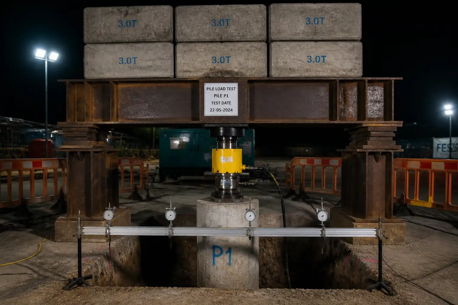
To verify geotechnical capacity and serviceability behavior of test piles and demonstrate compliance with project acceptance criteria.
Who uses this inspection and test plan
Contractor’s testing team, Geotechnical Engineer, QA/QC, HSE, and the Engineer/Employer’s Representative.
When this ITP is prepared and submitted
From pre-test approvals through setup, testing, unloading, and final reporting for each test pile.
Who receives or approves this ITP
The ITP is usually submitted to the client representative, consultant, resident engineer, or project management consultant for review and approval before the related work activity starts.
Inspection scope
Covers approvals, calibrations, pile head readiness, reaction system setup, instrumentation verification, loading/holding/unloading, and reporting.
Typical hold, witness, and review points
Hold: approvals, calibrations, reaction system, MTL hold, final report. Witness: pile head prep, reference frame setup, load increments and rebounds.
Typical inspection records
Calibration certificates, inspection checklists, anchor proof tests, load–settlement logs, DAS exports, photos, and signed final report.
Important approval note
This ITP is an AI-assisted editable starting point, not a pre-approved document. Before use on any project, all inspection activities, hold points, and acceptance criteria must be reviewed and approved by the relevant parties (superintendent, principal contractor, or client representative) in accordance with your contract and project quality plan.
Always verify acceptance criteria against your applicable drawings, specifications, and regulatory requirements. Hold points must be confirmed with the relevant authority before work proceeds past that point.
Inspection and test plan
| Activity | Inspection / Test | Acceptance Criteria | Responsibility | Record |
|---|---|---|---|---|
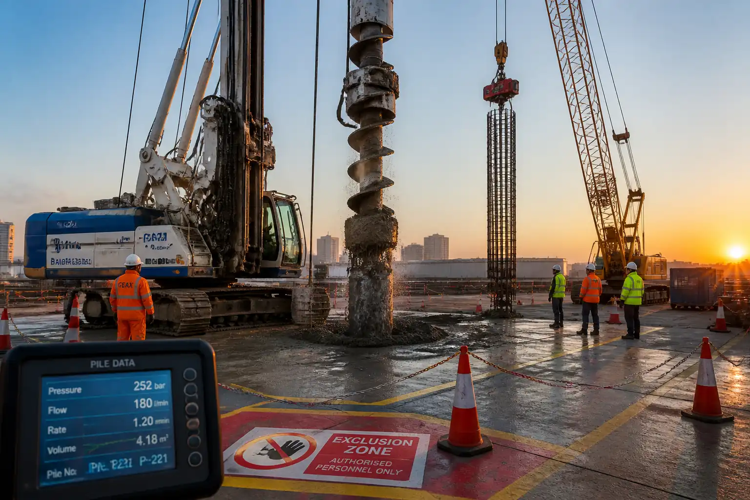
| Approvals and TWD | Review/Approval | Approved Method Statement, ITP, and TWD issued | Project Manager/Engineer | Approval letters; TWD package |
| Equipment calibration | Calibration verification | ISO/IEC 17025 traceable; within validity (≤6 months) [Verify] | QA/QC | Calibration certs |
| Pile head readiness | Flatness/perpendicularity | Evenness ≤ 1 mm/300 mm; perpendicularity ≤ 1/200; f'c achieved [Verify] | Engineer/Testing Supervisor | Checklist; photos |
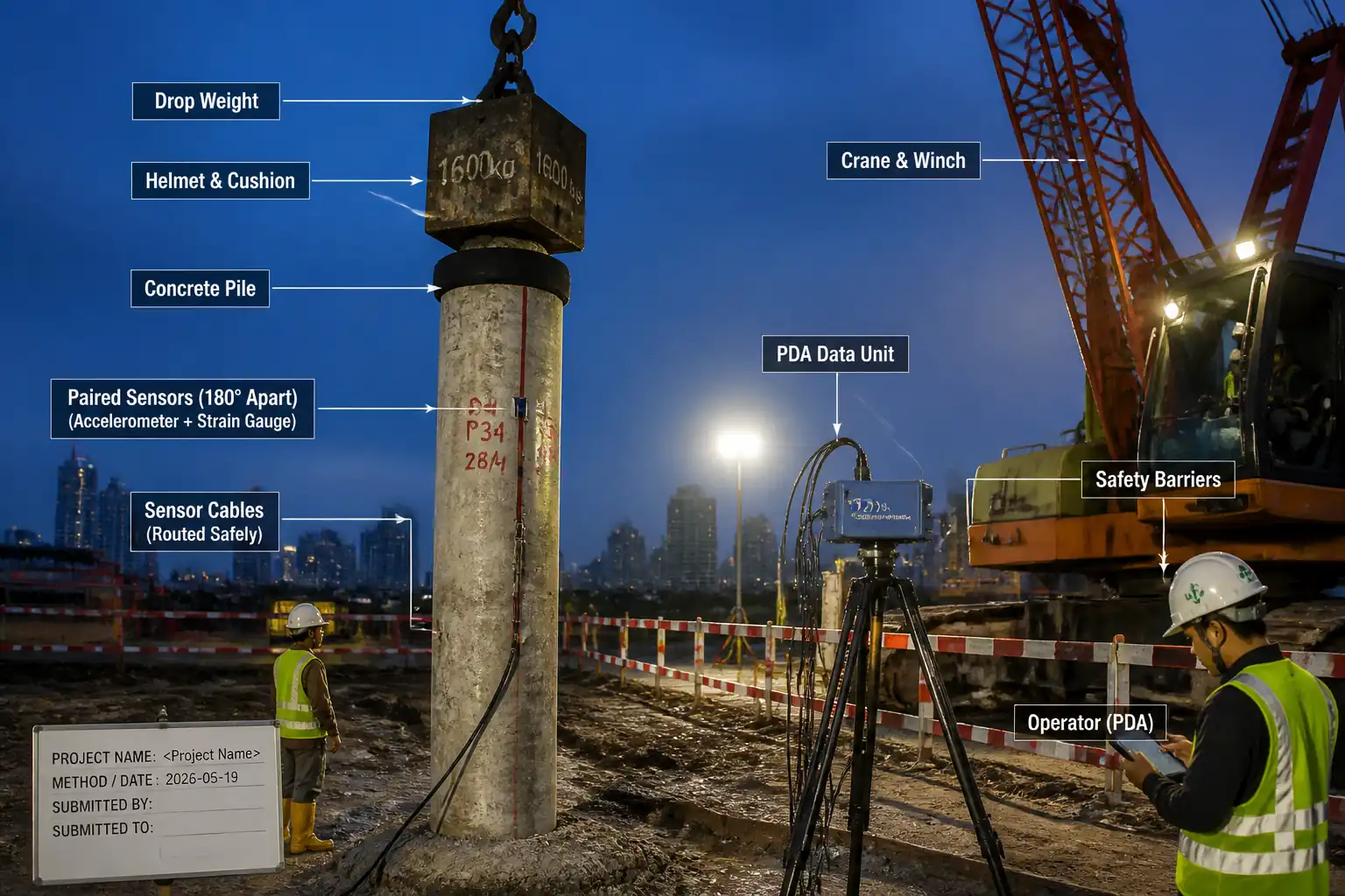
| Reaction system setup (Kentledge or Anchors) | TWD compliance; anchor proof tests (if used) | FoS and capacities per TWD; anchors proofed to ≥1.25×MTL [Verify] | TWD/Engineer | Inspection log; anchor test records |
| Reference frame installation | Influence zone clearance | Supports outside influence zone (≥3×D or ≥1 m beyond reactions) [Verify] | Surveyor/Engineer | Sketch; photos |
| Jack/load cell alignment | Eccentricity check | Eccentricity ≤ 5% D or ≤ 25 mm [Verify] | Testing Supervisor | Alignment log |
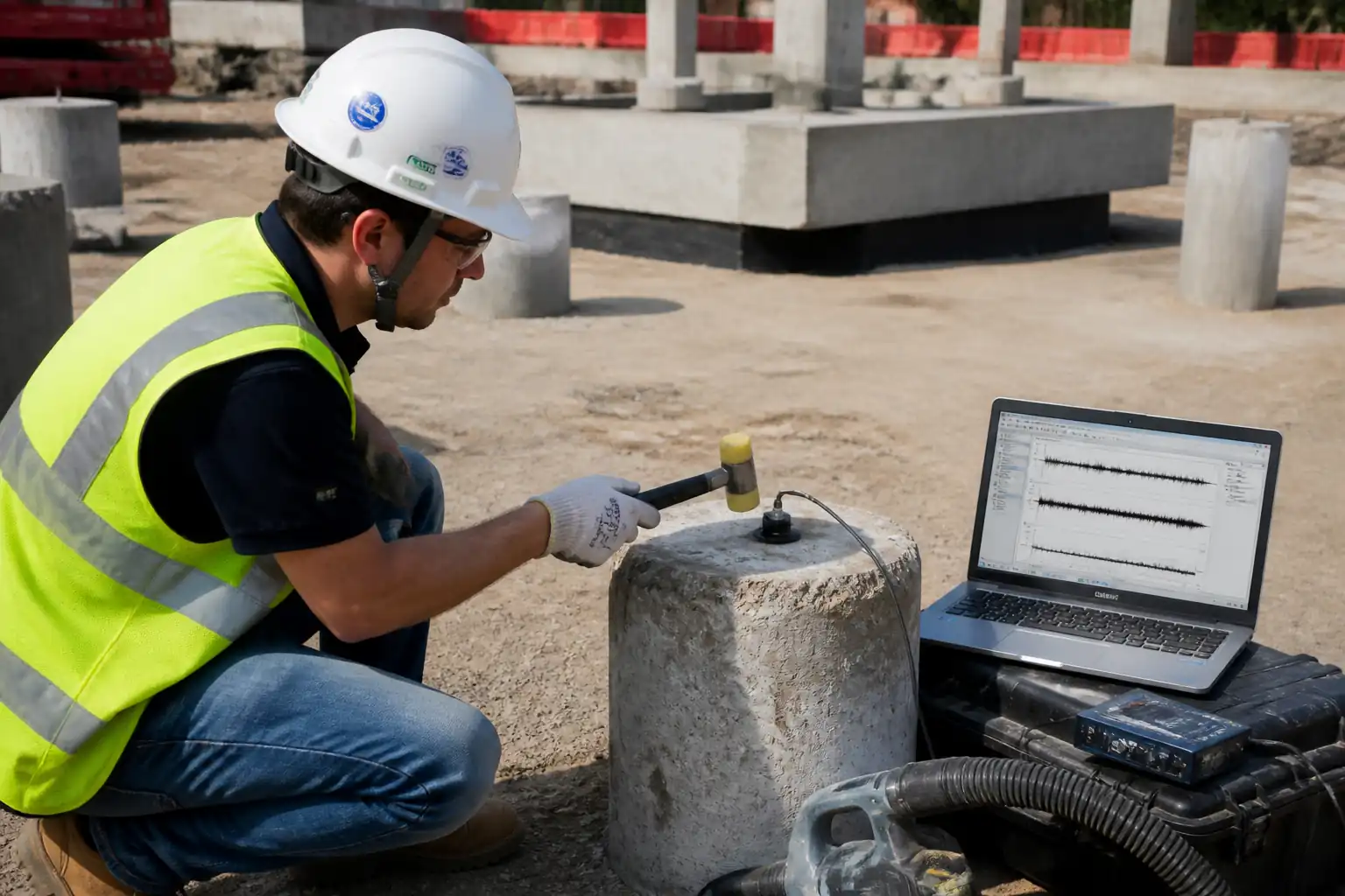
| Instrumentation zero and function | Zero/repeatability | Resolution ≤ 0.01 mm; baseline repeatability ≤ 0.1 mm | Instr. Tech/QA | Instrument check sheet |
| Seating load | Initial readings | Stable seating and baseline confirmed | Testing Supervisor | Field sheet |
| Load increments and holds | Settlement and creep rate | Hold until rate ≤ 0.25 mm/hr or min hold times per plan [Verify] | Testing Supervisor/Engineer | Load–settlement log; DAS files |
| Maximum load hold (MTL) | Creep at MTL | Creep within specified limit during final hour [Verify] | Engineer | Hold record |
| Unloading and rebound | Rebound readings | Rebound schedule completed | Testing Supervisor | Rebound log |
| Data analysis and report | Compliance check | Report meets standard and project acceptance criteria | Geotechnical Lead/QA | Signed report; datasets |
This table is a read-only public reference. Download the PDF or Excel version, or customize this ITP to edit it for your project.
Frequently asked questions
Related method statement
This Inspection and Test Plan is associated with the Method Statement: Static Axial Compression Load Testing of Piles (Kentledge or Reaction System) method statement, which describes the step-by-step construction sequence, resources, materials, equipment, safety controls, and environmental controls for this activity.
View the Method Statement: Static Axial Compression Load Testing of Piles (Kentledge or Reaction System) method statement →Continue with related inspection, method statement, article, and checklist resources.