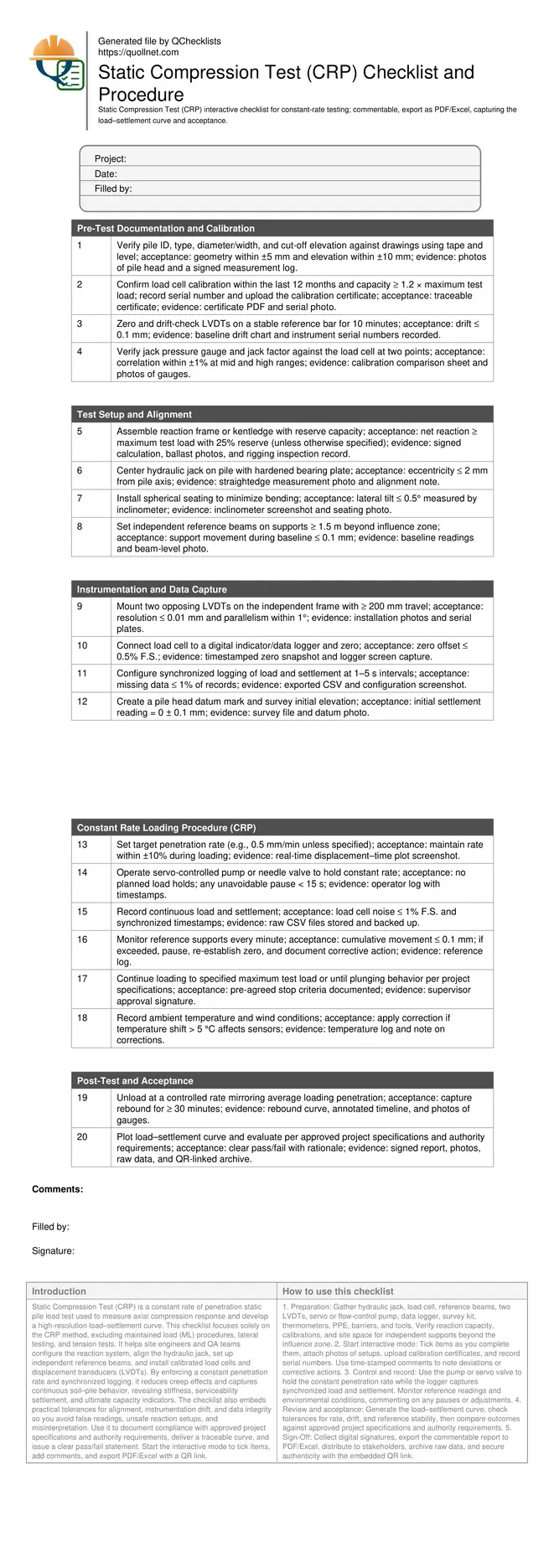
Static Compression Test (CRP) Checklist & Procedure
Definition: Static Compression Test (CRP) guides foundation teams in constant-rate pile loading to capture the load–settlement curve, verify acceptance against project criteria, and exclude maintained load procedures.
- Apply constant penetration rate to assess axial compression performance.
- Generate continuous load–settlement curve for capacity, stiffness, and serviceability.
- Use calibrated jack, load cell, LVDTs, servo control, synchronized logging.
- Interactive, commentable checklist; export results with QR code for traceability.
Static Compression Test (CRP) is a constant rate of penetration static pile load test used to measure axial compression response and develop a high-resolution load–settlement curve. This checklist focuses solely on the CRP method, excluding maintained load (ML) procedures, lateral testing, and tension tests. It helps site engineers and QA teams configure the reaction system, align the hydraulic jack, set up independent reference beams, and install calibrated load cells and displacement transducers (LVDTs). By enforcing a constant penetration rate and synchronized logging, it reduces creep effects and captures continuous soil–pile behavior, revealing stiffness, serviceability settlement, and ultimate capacity indicators. The checklist also embeds practical tolerances for alignment, instrumentation drift, and data integrity so you avoid false readings, unsafe reaction setups, and misinterpretation. Use it to document compliance with approved project specifications and authority requirements, deliver a traceable curve, and issue a clear pass/fail statement. Start the interactive mode to tick items, add comments, and export PDF/Excel with a QR link.
- Ensure reliable CRP execution by verifying calibration, reaction capacity, jack alignment, and independent reference frames. Maintain a constant penetration rate with servo-controlled pumping, collect synchronized load and settlement data, and prevent reference movement for dependable curves and defensible decisions.
- Reduce test risk by using dual LVDTs, zero-drift checks, and frequent reference-frame readings. Continuous time-stamped records and plotted displacement-rate control help avoid pauses, creep bias, and data loss, improving acceptance confidence and report credibility.
- Interactive online checklist with tick, comment, and export features secured by QR code. Attach photos, calibration certificates, CSV logs, and survey files. Generate a load–settlement curve, calculate key metrics, and issue a transparent pass/fail statement aligned with approved project specifications.
- Drive faster approvals with standardised tolerances for rate control, instrumentation drift, and alignment. The workflow separates setup, instrumentation, loading, and post-test review, producing a clear audit trail and reproducible results across multiple piles and rigs.
Pre-Test Documentation and Calibration
Test Setup and Alignment
Instrumentation and Data Capture
Constant Rate Loading Procedure (CRP)
Post-Test and Acceptance
What CRP Measures and When to Use It
CRP is a static pile load test that advances the pile head at a constant penetration rate to obtain a continuous load–settlement curve, capturing end-bearing and shaft friction mobilization without hold-period creep effects. It is well suited for characterizing stiffness and serviceability behavior, identifying plunging trends, and comparing performance across construction methods (bored, CFA, driven). Use CRP when the project requires a detailed, time-continuous response rather than discrete hold steps. This checklist intentionally excludes the maintained load method, lateral, and tension testing to keep the scope precise. By controlling the displacement rate and synchronizing measurements, you minimize variability from operator pauses and temperature drift. Acceptance focuses on alignment, sensor drift, rate control, and reference-frame stability so failures reflect ground–pile behavior, not setup errors. Real-world experience shows that small reference movements or jack eccentricity can distort curves and understate capacity. Applying the controls below ensures robust evidence and confident decisions.
- Use constant penetration rate to reduce creep bias.
- Focus on axial compression piles; exclude maintained load.
- Synchronize load and settlement with time-stamped logging.
- Stability of reference frame is critical for accuracy.
Setting Up Equipment for Reliable CRP Results
Reliable CRP outcomes depend on a rigid reaction system, precise alignment, and stable, independent measurement frames. Verify reaction capacity with a documented reserve to prevent uplift or slippage under peak loads. Center the hydraulic jack and use spherical seating to avoid bending. Install dual LVDTs on an independent reference beam placed beyond the influence zone so ground heave does not contaminate settlement readings. Confirm calibration for the load cell, jack pressure gauge, and LVDTs, then complete zero and drift checks before touching the pile. Survey and mark the datum, capture baseline photos, and configure the data logger for synchronized sampling. Small tolerances matter: a few tenths of a millimetre of drift or reference movement can mask the onset of plunging or distort stiffness. Clear photos, serial numbers, and baseline charts establish traceability and enable quick troubleshooting if anomalies appear mid-test.
- Reaction capacity documented with reserve margin.
- Jack centered; tilt and eccentricity controlled.
- Independent beams outside influence zone.
- Calibrations current; drift within tight limits.
- Synchronized logger preconfigured and verified.
Executing CRP and Interpreting Acceptance
Once the setup passes checks, select a target penetration rate (commonly around 0.5 mm/min, unless specified) and operate the pump or servo valve to hold that rate within a tight tolerance. Capture synchronized load and settlement at short intervals for a smooth, continuous curve. Monitor reference supports and environmental conditions; pause and correct if movement or temperature shifts compromise data. Load until the specified maximum test load or a defined plunging criterion is reached. Unload at a controlled rate and log rebound to characterize elastic recovery and residual settlement. Acceptance is judged against approved project specifications and authority requirements, emphasizing rate control, instrumentation stability, and curve quality. A clear pass/fail statement should reference observed stiffness, serviceability settlement, and any signs of plunging.
- Maintain penetration rate within agreed tolerance.
- No intentional holds; document unavoidable pauses.
- Record rebound to quantify residual settlement.
- Evaluate per approved specifications and requirements.
How to Use This CRP Static Compression Test Checklist
- Preparation: Gather hydraulic jack, load cell, reference beams, two LVDTs, servo or flow-control pump, data logger, survey kit, thermometers, PPE, barriers, and tools. Verify reaction capacity, calibrations, and site space for independent supports beyond the influence zone.
- Start interactive mode: Tick items as you complete them, attach photos of setups, upload calibration certificates, and record serial numbers. Use time-stamped comments to note deviations or corrective actions.
- Control and record: Use the pump or servo valve to hold the constant penetration rate while the logger captures synchronized load and settlement. Monitor reference readings and environmental conditions, commenting on any pauses or adjustments.
- Review and acceptance: Generate the load–settlement curve, check tolerances for rate, drift, and reference stability, then compare outcomes against approved project specifications and authority requirements.
- Sign-Off: Collect digital signatures, export the commentable report to PDF/Excel, distribute to stakeholders, archive raw data, and secure authenticity with the embedded QR link.
Call to Action
- Start Checklist Tick off tasks, leave comments on items or the whole form, and export your completed report to PDF or Excel—with a built-in QR code for authenticity.
- Download Excel - Static Compression Test (CRP)
- Download PDF - Static Compression Test (CRP)
- View Image - Static Compression Test (CRP)
Cite & Embed
“Static Compression Test (CRP) by Quollnet”
with a link to
this source page.
FAQ
Question: What is the difference between CRP and the maintained load method, and when should I choose CRP?
Question: What penetration rate should I use for a CRP test on piles?
Question: How long does a CRP test take, and when do I stop loading?
Question: What if the independent reference frame moves during testing?
Question: How is acceptance determined after running a CRP test?
Related Articles
Broader reading and guidance connected to this checklist topic.


Is It Important To Customize Your Qr Code And How To Do It?


Master Construction Project Cashflow With Cashflowpot
Related Checklists
Keep the workflow moving with nearby templates chosen from similar checklist content.