Method Statement: Static Axial Compression Load Testing of Piles (Kentledge or Reaction System) – Method Statement
AI-assisted method statement with matching ITP, PDF download, and Excel export.
More than a static template
Unlike a downloadable Word or PDF template, this method statement is an AI-assisted editable starting point connected directly to a matching Inspection and Test Plan. Every section is structured, project-adaptable, and ready to export.
- AI-assisted drafting — Customize every section with AI for your specific project scope.
- Linked ITP — A matching inspection and test plan is generated alongside the method statement.
- Multiple export formats — Download as a formatted PDF or editable Excel spreadsheet.
- Editable starting point, not a final document — Review, verify, and adjust all content against your project requirements before use.
Static template vs. Quollnet workflow
| Feature | Static template | Quollnet |
|---|---|---|
| Project-specific content | Manual fill-in required | AI-assisted customization |
| Linked ITP | Separate document, no link | Matching ITP included |
| Export formats | Usually PDF only | PDF and Excel |
| Structured sections | Free-form layout | 13 standardized sections |
| Saved to your account | Local file only | Cloud-saved, reusable |
| Content accuracy | You verify everything | AI-assisted, you still verify |
| Cost | Often free but time-intensive | Free to customize and download |
What you can customize
When you save this method statement to your account, every section becomes editable. The following 13 sections are included:
- Scope — Defines the activity and its boundaries.
- References — Standards, specifications, and drawings.
- Responsibilities — Roles and accountabilities.
- Resources — Labour, plant, and equipment summary.
- Materials — Materials and compliance requirements.
- Equipment — Tools and equipment details.
- Prerequisites — Hold points and pre-conditions.
- Method sequence — Step-by-step construction sequence.
- Safety controls — HSE risk controls and PPE.
- Environmental controls — Environmental mitigation measures.
- QA/QC — Quality inspection and test requirements.
- ITP — Inspection and Test Plan table (has its own page).
- Attachments — Referenced drawings and documentation.
Why this method statement is used
This method statement is used to define and communicate the approved procedure for carrying out method statement: static axial compression load testing of piles (kentledge or reaction system) on site. It ensures the work is planned in advance, the correct resources and controls are in place, and all personnel understand responsibilities, sequence, quality requirements, and safety controls before work begins. It aligns site execution with the documented scope and acceptance expectations.
Who uses this method statement
This method statement is used by contractors, site supervisors, project engineers, QA/QC engineers, HSE officers, consultants, and client representatives. It serves as a shared reference for planning, execution, supervision, inspection, and approval of the activity on site.
When it is prepared and submitted
The method statement is prepared before the work activity starts and submitted as part of the pre-construction documentation package for review and approval.
Who reviews or approves it
The method statement is usually submitted to the client representative, consultant, resident engineer, or project management consultant for review and approval before the work commences.
Important approval note
This method statement is an AI-assisted editable starting point, not a pre-approved document. Before use on any project, all content must be reviewed and approved by the relevant parties (superintendent, principal contractor, or client representative) in accordance with your contract and project quality plan.
For example: if your specification requires a departure from a referenced standard, that departure must be documented and approved separately — this method statement will not capture that automatically. Always verify against your applicable drawings, specifications, and regulatory requirements.
Method statement content
Scope
Overview
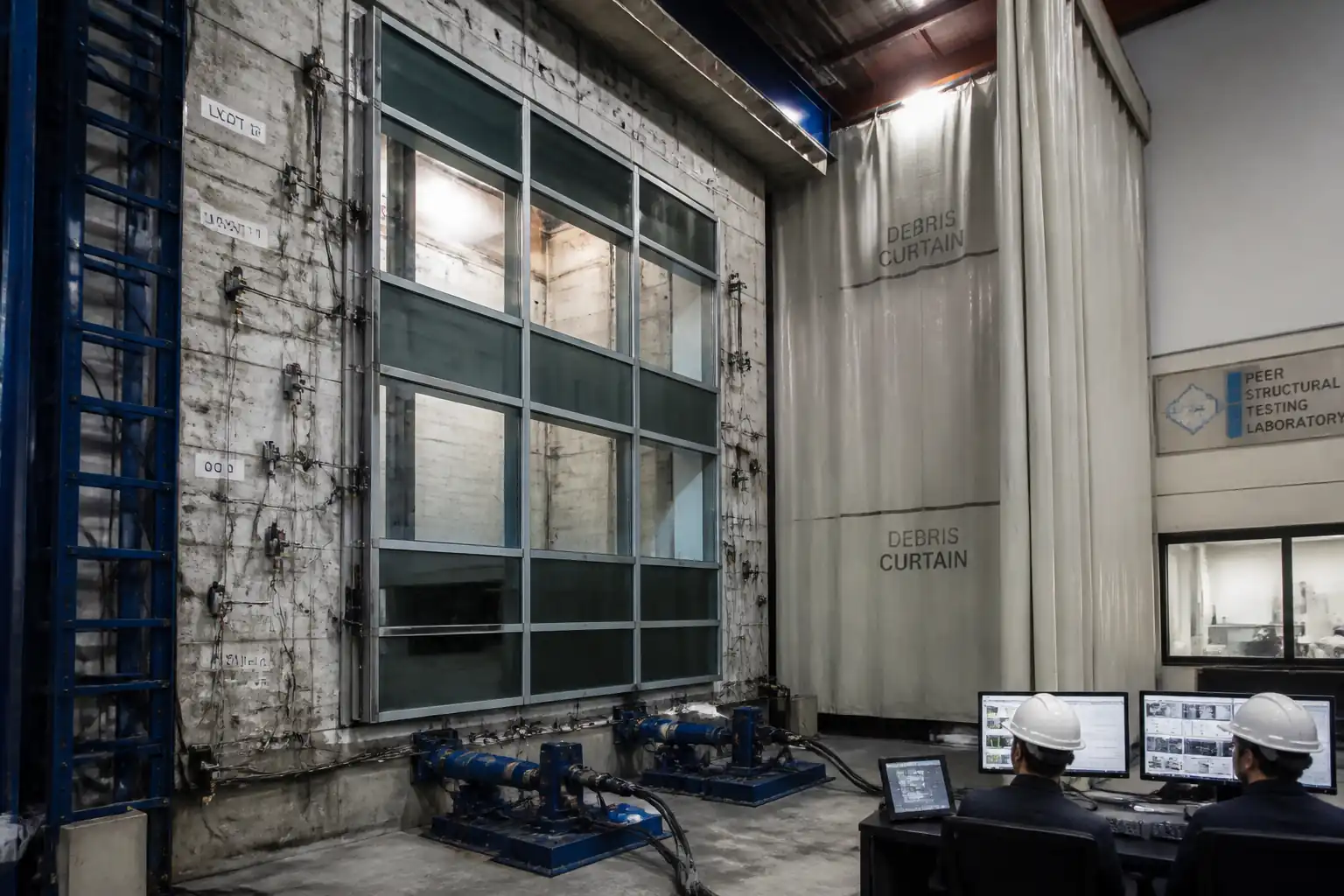
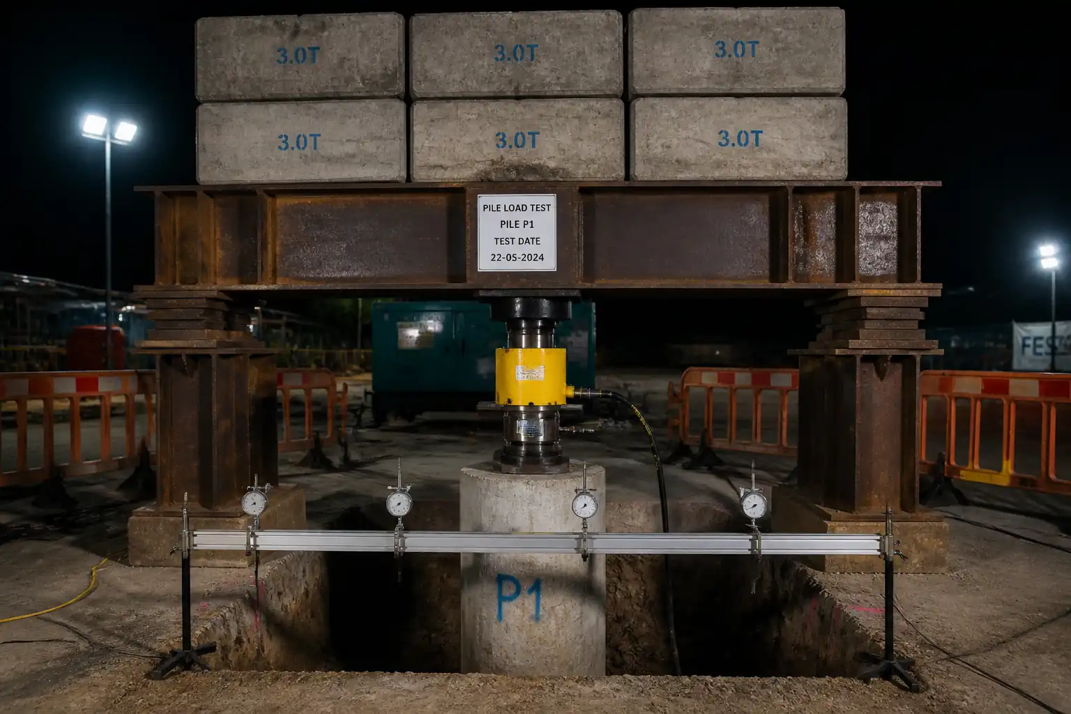
This method statement defines the procedures for static load testing of foundation piles under axial compression using either a kentledge (dead-weight) platform or a reaction system comprising tension anchors/reaction piles and a reaction frame. It covers pre-test verification, reaction system installation, jack and instrumentation setup, load application in increments with hold durations, settlement monitoring, unloading, demobilization, and reporting.
Inclusions
- Maintained-load compression testing to determine load–settlement behavior and confirm geotechnical and structural performance.
- Use of a calibrated hydraulic jack with in-line load cell and displacement instrumentation (dial gauges or LVDTs) on an independent reference frame.
- Two reaction options: (a) kentledge stack and load platform; (b) reaction anchors/piles with reaction beam/frame.
- Test scheduling: load increments, hold criteria, reading frequency, unloading, rebound observations, and acceptance evaluation.
- QA/QC, HSE measures, and inspection/testing plan (ITP).
Exclusions
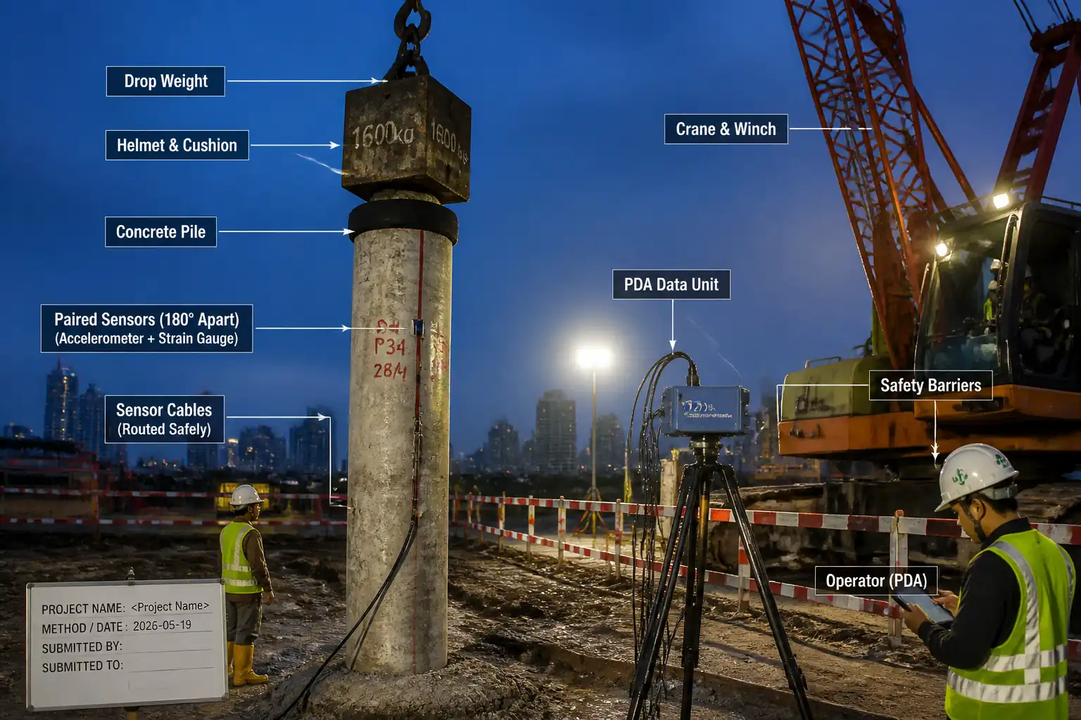
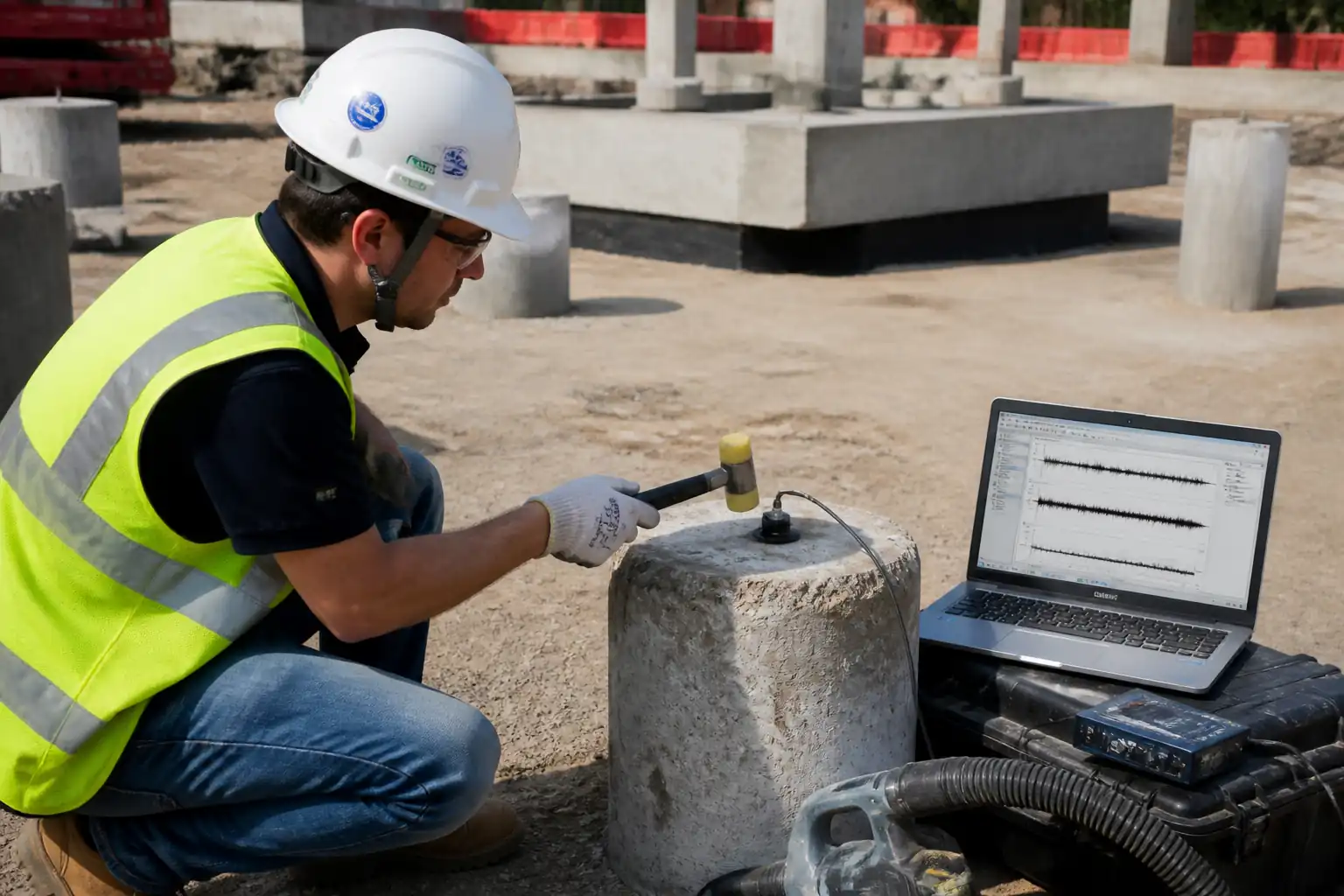
- Constant Rate of Penetration (CRP/CRP) tests, lateral/tension tests, bi-directional (O-cell) testing, dynamic PDA testing, and integrity testing (e.g., PIT/CSL).
- Permanent works design of the pile; this document addresses the test only.
Key Objectives
- Verify ultimate/geotechnical capacity and serviceability behavior per project acceptance criteria.
- Confirm structural adequacy of the test pile head and load path under the maximum test load (MTL).
[All project-specific parameters, acceptance limits, and load schedules to be verified per project specifications.]
References
| Document Type | Reference / Number | Revision | Notes |
|---|---|---|---|
| Standard | ASTM D1143/D1143M | Use Procedure A/B as specified [Verify]. | |
| Standard | EN ISO 22477-1 | Follow national annex as applicable. | |
| Code | EN 1997-1/EN 1997-2 | Use project geotechnical parameters. | |
| Code/Standard | EN 1990/1991; BS 7121; ASME B30 [Verify] | Include grillage/mats design for kentledge and reaction frame checks. | |
| Standard | ISO 376; ISO/IEC 17025; ASTM E4/E74 | Within previous 6 months [Verify]. | |
| Guidance | ICE; CIRIA | ||
| HSE | [Verify per jurisdiction] |
Responsibilities
| Role | Responsibility | Name / Party |
|---|---|---|
| PM | Project Manager | Contractor |
| Engineer | Geotechnical Lead | Contractor |
| Engineer | TWD Engineer | Contractor/Designer |
| Supervisor | Testing Supervisor | Specialist |
| QA/QC | QA/QC Engineer | Contractor |
| HSE | HSE Manager | Contractor |
| Technician | Surveyor/Instr. Tech | Contractor/Specialist |
| Lifting | Appointed Person | Contractor |
Resources
| Resource Type | Description | Quantity | Remarks |
|---|---|---|---|
| Manpower | 3–5 technicians/operators for jack operation and readings | 3–5 | |
| Manpower | 1–2 personnel for setup, verification, and data logging | 1–2 | |
| Manpower/Plant | For kentledge and frame assembly | As required | |
| Manpower | Site HSE oversight and permits | 1 |
Materials
| Material | Specification / Grade | Quantity | Remarks |
|---|---|---|---|
| S355 or equivalent [Verify] | As per setup | ||
| Non-shrink grout | ASTM C1107/EN 1504 [Verify] | As required | |
| Hardwood/Steel | As designed |
Equipment
| Equipment | Capacity / Type | Quantity | Inspection Required |
|---|---|---|---|
| Hydraulic jack | As required | 1 (plus standby if critical) | Yes |
| 1 | Yes | ||
| 1 | Yes | ||
| 2–4 | Yes | ||
| 1 set | Yes | ||
| As designed | Yes | ||
| As designed | Yes | ||
| 1 | Yes | ||
| 1 | Yes | ||
| As required | Yes |
Prerequisites
Approvals and Documentation
- Approved test method statement, ITP, and test schedule from the Engineer.
- Temporary Works Design (TWD) for chosen reaction system (kentledge OR reaction anchors/frame), including drawings, calculations, checks, and materials list; independent category check as required [Verify per project].
- Lifting Plan, Rigging Register, and permits (PTW, Hot/Cold work as needed).
- Calibrations: load cell and pressure gauge within 6 months; displacement devices function check; certifications traceable to ISO/IEC 17025 [Verify per project].
Site and Pile Readiness
- Platform: level, compacted, and with verified bearing capacity and drainage. Bearing pressure under mats/grillage ≤ allowable with FoS ≥ 2 against bearing failure [Verify].
- Pile head prepared to design cut level; laitance removed; bearing surface flat and perpendicular to pile axis. Acceptance: deviation from perpendicular ≤ 1/200; surface evenness within 1 mm under straightedge over 300 mm [Verify].
- Pile age and concrete strength achieved before testing (e.g., ≥ 28 days or f'c ≥ 0.8× design strength) [Verify per project].
- As-built survey of test pile position and top elevation completed.
Utilities and Adjacent Assets
- Utility scans and permits for reaction anchors; clearance from existing structures confirmed. Reaction/influence zones assessed to avoid affecting nearby piles/structures [Verify per design].
Test Parameters (to be verified project-specifically)
- Working Load (WL) and Maximum Test Load (MTL), typically MTL = 1.5–2.0 × WL for maintained-load tests [Verify per spec].
- Load increment size: typically 10–25% WL per step [Verify].
- Hold criterion: at each increment maintain until the pile movement rate ≤ 0.25 mm/hr or until a specified hold duration elapses (e.g., 30–60 min), whichever occurs later at key stages; at MTL hold ≥ 60–120 min [Verify per standard/spec].
- Acceptance at service load: total settlement and creep limits per project (typical: settlement at WL ≤ 10–25 mm; creep at WL ≤ 0.25 mm over final 1 hr) [Verify].
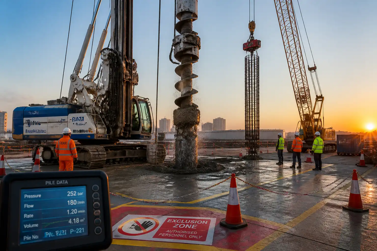
Exclusion Zones and Weather
- Establish barriers and exclusion zones around reaction system footprint and under suspended loads. Provide weather protection (tents/shrouds) against wind/temperature effects on gauges.
Method Sequence
| Step | Activity | Description | Responsibility | Inspection / Hold Point |
|---|---|---|---|---|
| 1 | Pre-test briefing and permits | Conduct toolbox talk covering method, load schedule, hazards, emergency plan; verify PTW/lifting permits in force. | Testing Supervisor/HSE | TBT attendance check |
| 2 | Pile head preparation and survey | Trim, level, and clean pile head; verify perpendicularity and elevation; install bearing plate if required. | Construction/Test team | Engineer check |
| 3A | Reaction system setup – Kentledge (Option) | Assemble load platform and stack kentledge blocks gradually and symmetrically; verify ground bearing and stability; position reaction beam centered on pile. | TWD/Construction | TWD compliance |
| 3B | Reaction system setup – Anchors/Frame (Option) | Install tension anchors/reaction piles per TWD; proof load anchors; assemble and align reaction frame/beam over test pile. | TWD/Construction | Anchor test |
| 4 | Reference frame installation | Install independent reference beam/frame with supports outside influence zone; mount gauge brackets around pile. | Survey/Instr. Tech | Deflection check |
| 5 | Jack, load cell, and alignment | Place spherical-seated jack and in-line load cell concentric with pile axis; install distribution/bearing plates as needed. | Testing Supervisor | Alignment check |
| 6 | Instrumentation setup and zeroing | Install 2–4 displacement gauges or LVDTs at 90°–120° spacing on reference frame; set initial readings; connect data logger if used. | Instr. Tech | Function/linearity |
| 7 | Seating load and baseline readings | Apply seating load ~5–10% WL; hold 5–10 min; record readings every 1–5 min; unload to zero and confirm baseline repeatability. | Testing Supervisor | Readings review |
| 8 | Maintained load test – Loading phases | Increase load in increments (typ. 10–25% WL) up to WL and then to MTL per approved schedule; maintain each increment until movement rate ≤ 0.25 mm/hr or minimum hold time met (e.g., 15–30 min early stages, 60 min at WL) [Verify]. Record load and settlement at specified intervals. | Testing Supervisor | Engineer witness at key holds |
| 9 | Maximum load hold (MTL) | Maintain MTL for 60–120 min or until creep rate ≤ 0.25 mm/hr over last 60 min [Verify]. Continue frequent readings. | Testing Supervisor | Engineer hold point |
| 10 | Unloading sequence and rebound | Reduce load in equal decrements to zero (same steps as loading); at each decrement hold ~5–15 min; at zero load, continue rebound readings at intervals (e.g., 5, 10, 15, 30, 60 min) [Verify]. | Testing Supervisor | Engineer witness (as required) |
| 11 | Demobilization | Remove jack and instrumentation; dismantle reaction system in reverse order; inspect pile head and surrounding area; reinstate site. | Construction/Test team | Handover check |
| 12 | Data analysis and reporting | Process load–settlement data; generate curves; interpret per standard and project criteria (e.g., Davisson, Chin, De Beer as required [Verify]); compile report with raw data, calibrations, photos, as-builts, and conclusions. | Geotechnical Lead | Technical review |
Health, Safety, and Environment (HSE) – Safety Controls
Task-Specific Hazards and Controls
1) High-pressure hydraulics (jack/hoses)
- Consequence: Hose burst, whipping, sudden load loss, injection injury.
- Engineering/Procedural Control: Use hoses and fittings rated ≥ 1.5 × max pressure with whip checks; install pressure relief valve; keep personnel clear of potential whip paths; pressure increase in small, controlled steps; never adjust fittings under pressure.
- PPE: Safety helmet, safety glasses/face shield, gloves rated for hydraulic fluids, long sleeves, safety boots.
- Collective Measure: Physical barriers around jacking area; exclusion zone marked 2 m radius minimum [Verify].
- Inspection/Permit/Supervision: Pre-use hose inspection; pressure test certs; Testing Supervisor authorization before pressurizing; PTW as applicable.
2) Reaction system instability (kentledge or anchor frame)
- Consequence: Overturning/sliding/collapse causing crush injuries or structural damage.
- Engineering/Procedural Control: TWD-approved design; symmetrical stacking of kentledge; no personnel on or under loaded components; anchors proof tested; verify bolt torques and welds per TWD.
- PPE: Helmet, high-vis, steel-toe boots, gloves.
- Collective Measure: Rigid barriers and signage; tag lines and spotters during handling.
- Inspection/Permit/Supervision: TWD inspection and sign-off; Engineer witness before loading; periodic checks for settlement/tilt during test.
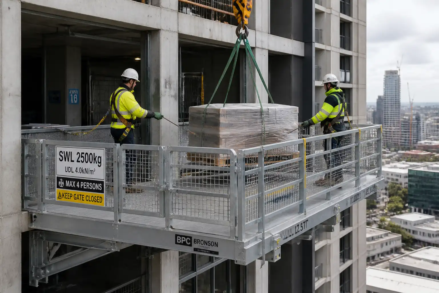
3) Lifting operations for kentledge/frames
- Consequence: Dropped loads, struck-by, crushing.
- Engineering/Procedural Control: Appointed Person’s Lifting Plan; certified crane/rigging; pre-lift meeting; controlled laydown area; weather limits per crane chart.
- PPE: Helmet with chin strap, gloves, boots, high-vis; radio comms.
- Collective Measure: Exclusion zone; banksman control; tag lines.
- Inspection/Permit/Supervision: LOLER/third-party certs [Verify per jurisdiction]; daily rigging inspection; lift supervisor present.
4) Working near open pile heads, trip hazards, and pinch points
- Consequence: Trips/falls, finger crush injuries during placement of plates/shims.
- Engineering/Procedural Control: Keep area clear and level; use pinch bars, not hands, to place shims; maintain good housekeeping; use kneeling mats where needed.
- PPE: Gloves, boots, eye protection.
- Collective Measure: Edge protection or covers when unattended.
- Inspection/Permit/Supervision: Supervisor to brief and monitor; housekeeping checks each shift.
5) Structural failure of pile head or bearing plates
- Consequence: Sudden settlement, ejection of components, injury.
- Engineering/Procedural Control: Verify concrete strength and pile head integrity; use bearing plates sized to keep contact stress ≤ allowable; use spherical seat to accommodate minor misalignment.
- PPE: Helmet, face shield when close to jack, gloves, boots.
- Collective Measure: Stand-off distance for non-essential staff; shielding where practicable.
- Inspection/Permit/Supervision: Engineer acceptance of pile head; pre-load inspection of load path.
6) Reference frame disturbance
- Consequence: Invalid readings, unsafe retesting.
- Engineering/Procedural Control: Independent supports outside influence zone; physical protection against knocks; routine checks for drift.
- PPE: As general site PPE.
- Collective Measure: Barrier tape and signage around reference supports.
- Inspection/Permit/Supervision: Reading cross-checks between gauges; Supervisor sign-off before proceeding to next load increment.
7) Night/low-light operations
- Consequence: Poor visibility, increased error, incidents.
- Engineering/Procedural Control: Task lighting ≥ 200 lux at gauges and work area; backup power; reflective PPE.
- PPE: High-vis, headlamps as needed.
- Collective Measure: Light towers positioned to avoid glare; cable management.
- Inspection/Permit/Supervision: HSE inspection before night shift; electrical PAT testing.
8) Noise and vibration from pumps/cranes
- Consequence: Hearing damage, nuisance.
- Engineering/Procedural Control: Position pumps away from personnel; consider acoustic shielding.
- PPE: Hearing protection where >85 dB(A).
- Collective Measure: Noise monitoring if required.
- Inspection/Permit/Supervision: HSE to verify controls per local regulations [Verify].
9) Adverse weather (wind, rain, temperature)
- Consequence: Instrument drift, slippery surfaces, crane derating.
- Engineering/Procedural Control: Weather thresholds in method; tents/shrouds for gauges; pause lifts per limits.
- PPE: Weather-appropriate PPE.
- Collective Measure: Grit/sand for slips; non-slip mats.
- Inspection/Permit/Supervision: Supervisor weather check before critical operations.
[All controls to be verified per Project HSE Plan and local regulations.]
Environmental Controls
Key Environmental Aspects and Mitigations
- Fuel/hydraulic oil spills: Use drip trays under pumps and jacks; spill kits within 20 m; refuel in designated bunded area; report and clean up spills immediately per plan.
- Ground bearing and settlement: Design mats/grillage to limit contact pressure; monitor mat settlements; adjust stack if differential settlement occurs; avoid soft ground during/after heavy rainfall.
- Noise and hours of work: Schedule noisy operations within permitted hours; deploy acoustic barriers near receptors if required; maintain equipment to reduce noise.
- Waste and housekeeping: Remove debris, timber off-cuts, and packaging; segregate waste streams; dispose via licensed carriers.
- Dust and mud control: Wet sweeping for dust; wheel-wash or mud mats at site egress; cover kentledge blocks in transit to prevent dust.
- Light spill at night: Aim lights downward; avoid glare to roadways/buildings; use shielded fixtures.
- Water protection: Prevent grout or cement washout from reaching drains; use lined mixing/cleaning areas; no discharge without permit.
[Verify additional local environmental requirements and permits per project EMP.]
Quality Assurance and Quality Control
QA/QC Controls
- Calibration and Certification: Verify ISO/IEC 17025-traceable calibration certificates for load cell and pressure gauge (within 6 months [Verify]) and function checks for displacement gauges. Maintain copies on site.
- Instrument Verification: Cross-check readings between load cell and pressure gauge (differences typically ≤ 5% at steady state) [Verify]. Check zero stability before/after test; re-zero as permitted.
- Alignment and Eccentricity: Measure and record jack/load cell concentricity. Maintain eccentricity ≤ 5% of pile diameter or ≤ 25 mm (smaller governs) [Verify].
- Reference Frame Stability: Confirm no measurable movement of reference supports; monitor with tell-tales or auxiliary gauge.
- Reading Protocol: Time-synchronized logging; during load changes and first 10–15 min of each hold, take readings at 1–2 min intervals, then every 5–10 min until hold criterion met [Verify].
- Load Schedule Compliance: Do not advance to next increment until hold/creep criterion satisfied and the system is stable.
- Data Integrity: Use indelible ink on field sheets; sign and date by recorder and supervisor; back up electronic files daily with checksum.
- Acceptance Evaluation: Assess settlement at WL against project limit (typ. 10–25 mm [Verify]); evaluate creep at WL and at MTL per spec (e.g., ≤ 0.25 mm in last hour [Verify]); interpret ultimate capacity using specified method(s) (e.g., Davisson offset, Chin-Kondner, De Beer) as required.
- Nonconformance: If equipment drift, reference frame disturbance, or reaction instability occurs, pause test, document, rectify, and if needed, repeat affected stages. Raise NCR and obtain Engineer direction.
- Records: Field data sheets, calibration certificates, TWD approvals, permits, inspection checklists, photos, and final report archived per project document control.
Attachments
Attached/Referenced Documents
- Approved Temporary Works Design package (drawings, calculations, checks) for reaction system.
- Lifting Plan and rigging certificates.
- Calibration certificates for load cell, pressure gauge/transducer, displacement gauges; equipment data sheets.
- Site layout and barrier/exclusion zone plan.
- Field data sheet templates (time–load–settlement logs) and example curves.
- Risk Assessment/Job Safety Analysis and PTWs.
- Pre- and post-test photographic record.
- As-built survey of reaction system and reference frame locations.
- Final test report and raw data exports.
[All attachments to be controlled per project document control procedures.]
This content is a read-only public reference. Download or customize to get an editable version.
ITP preview
The first inspection activities from the linked ITP for Method Statement: Static Axial Compression Load Testing of Piles (Kentledge or Reaction System):
| Activity | Inspection / Test | Acceptance Criteria | Responsibility | Record |
|---|---|---|---|---|
| Approvals and TWD | Review/Approval | Approved Method Statement, ITP, and TWD issued | Project Manager/Engineer | Approval letters; TWD package |
| Equipment calibration | Calibration verification | ISO/IEC 17025 traceable; within validity (≤6 months) [Verify] | QA/QC | Calibration certs |
| Pile head readiness | Flatness/perpendicularity | Evenness ≤ 1 mm/300 mm; perpendicularity ≤ 1/200; f'c achieved [Verify] | Engineer/Testing Supervisor | Checklist; photos |
Showing 3 of 12 inspection activities. View full ITP →
Related Inspection and Test Plan
An Inspection and Test Plan (ITP) is available for Method Statement: Static Axial Compression Load Testing of Piles (Kentledge or Reaction System). The ITP defines the inspection activities, acceptance criteria, hold and witness points, responsible parties, and records required to verify the work described in this method statement.
View the Method Statement: Static Axial Compression Load Testing of Piles (Kentledge or Reaction System) ITP →Frequently asked questions
Continue with related Quollnet resources connected to this method statement.