Method Statement – High‑Strain Dynamic Pile Testing (PDA) with CAPWAP Signal Matching – Method Statement
AI-assisted method statement with matching ITP, PDF download, and Excel export.
More than a static template
Unlike a downloadable Word or PDF template, this method statement is an AI-assisted editable starting point connected directly to a matching Inspection and Test Plan. Every section is structured, project-adaptable, and ready to export.
- AI-assisted drafting — Customize every section with AI for your specific project scope.
- Linked ITP — A matching inspection and test plan is generated alongside the method statement.
- Multiple export formats — Download as a formatted PDF or editable Excel spreadsheet.
- Editable starting point, not a final document — Review, verify, and adjust all content against your project requirements before use.
Static template vs. Quollnet workflow
| Feature | Static template | Quollnet |
|---|---|---|
| Project-specific content | Manual fill-in required | AI-assisted customization |
| Linked ITP | Separate document, no link | Matching ITP included |
| Export formats | Usually PDF only | PDF and Excel |
| Structured sections | Free-form layout | 13 standardized sections |
| Saved to your account | Local file only | Cloud-saved, reusable |
| Content accuracy | You verify everything | AI-assisted, you still verify |
| Cost | Often free but time-intensive | Free to customize and download |
What you can customize
When you save this method statement to your account, every section becomes editable. The following 13 sections are included:
- Scope — Defines the activity and its boundaries.
- References — Standards, specifications, and drawings.
- Responsibilities — Roles and accountabilities.
- Resources — Labour, plant, and equipment summary.
- Materials — Materials and compliance requirements.
- Equipment — Tools and equipment details.
- Prerequisites — Hold points and pre-conditions.
- Method sequence — Step-by-step construction sequence.
- Safety controls — HSE risk controls and PPE.
- Environmental controls — Environmental mitigation measures.
- QA/QC — Quality inspection and test requirements.
- ITP — Inspection and Test Plan table (has its own page).
- Attachments — Referenced drawings and documentation.
Why this method statement is used
This method statement is used to define and communicate the approved procedure for carrying out method statement – high‑strain dynamic pile testing (pda) with capwap signal matching on site. It ensures the work is planned in advance, the correct resources and controls are in place, and all personnel understand responsibilities, sequence, quality requirements, and safety controls before work begins. It aligns site execution with the documented scope and acceptance expectations.
Who uses this method statement
This method statement is used by contractors, site supervisors, project engineers, QA/QC engineers, HSE officers, consultants, and client representatives. It serves as a shared reference for planning, execution, supervision, inspection, and approval of the activity on site.
When it is prepared and submitted
The method statement is prepared before the work activity starts and submitted as part of the pre-construction documentation package for review and approval.
Who reviews or approves it
The method statement is usually submitted to the client representative, consultant, resident engineer, or project management consultant for review and approval before the work commences.
Important approval note
This method statement is an AI-assisted editable starting point, not a pre-approved document. Before use on any project, all content must be reviewed and approved by the relevant parties (superintendent, principal contractor, or client representative) in accordance with your contract and project quality plan.
For example: if your specification requires a departure from a referenced standard, that departure must be documented and approved separately — this method statement will not capture that automatically. Always verify against your applicable drawings, specifications, and regulatory requirements.
Method statement content
Scope
Overview
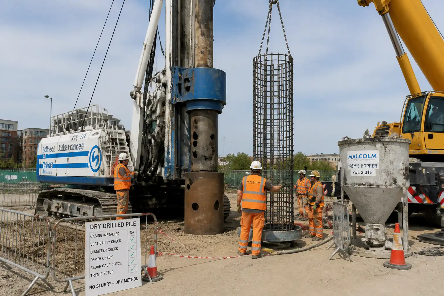
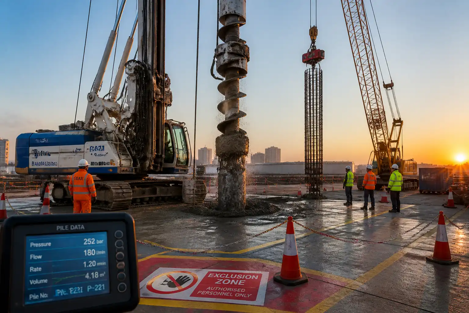
This method statement covers planning, execution, analysis, and reporting of High-Strain Dynamic Pile Testing (PDA) for driven piles and cast-in-place bored piles (where feasible), including:
- Preparation of pile head and instrumentation zones.
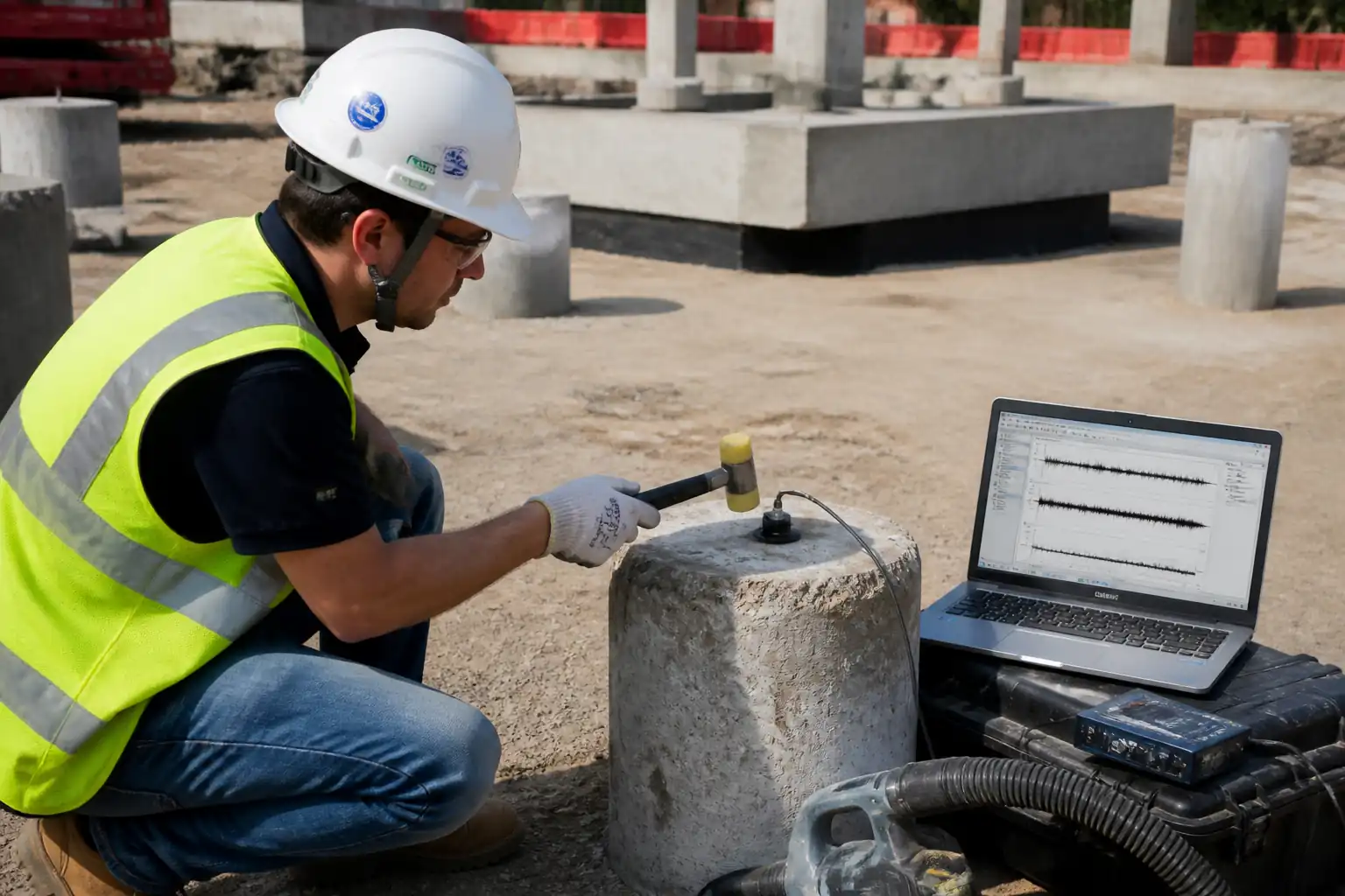
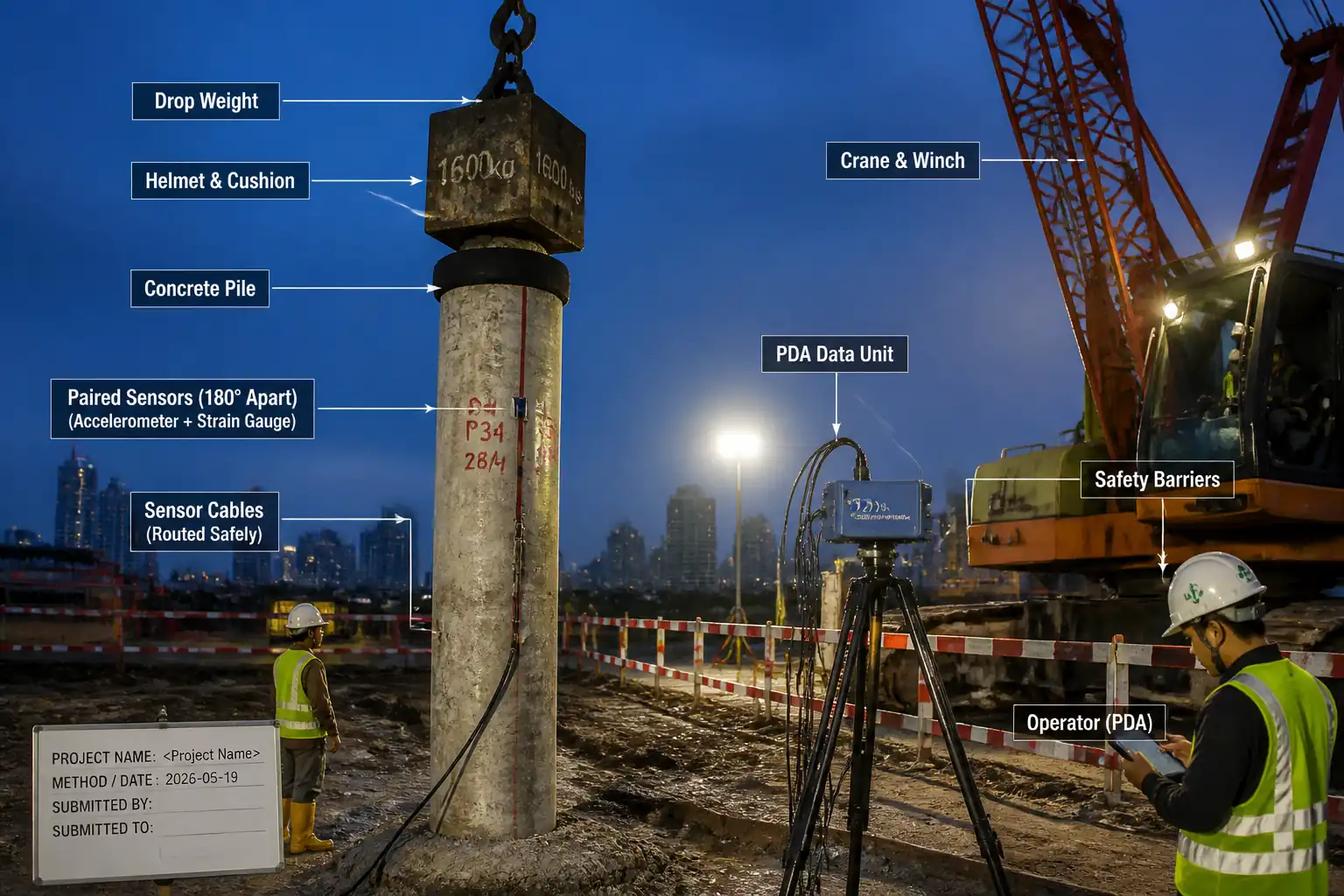
- Installation of strain transducers and accelerometers (paired, 180° apart at the same elevation).
- Impact application using a pile driving hammer or controlled drop weight with energy control and monitoring.
- Real-time data acquisition and on-site integrity screening.
- Signal matching analysis (e.g., CAPWAP) to estimate ultimate capacity, load distribution (shaft/toe), quake and damping parameters.
- Determination and verification of Case damping factor (Jc) used for Case Method capacity estimation.
- Reporting of capacities, stresses, and recommendations.
Inclusions
- Pre-test submittals, equipment calibration verification, HSE controls, QA/QC, and Inspection & Test Plan (ITP).
- Testing during initial drive (ID) and/or re-strike (RTS) after specified set-up time [Verify per project specifications].
Exclusions
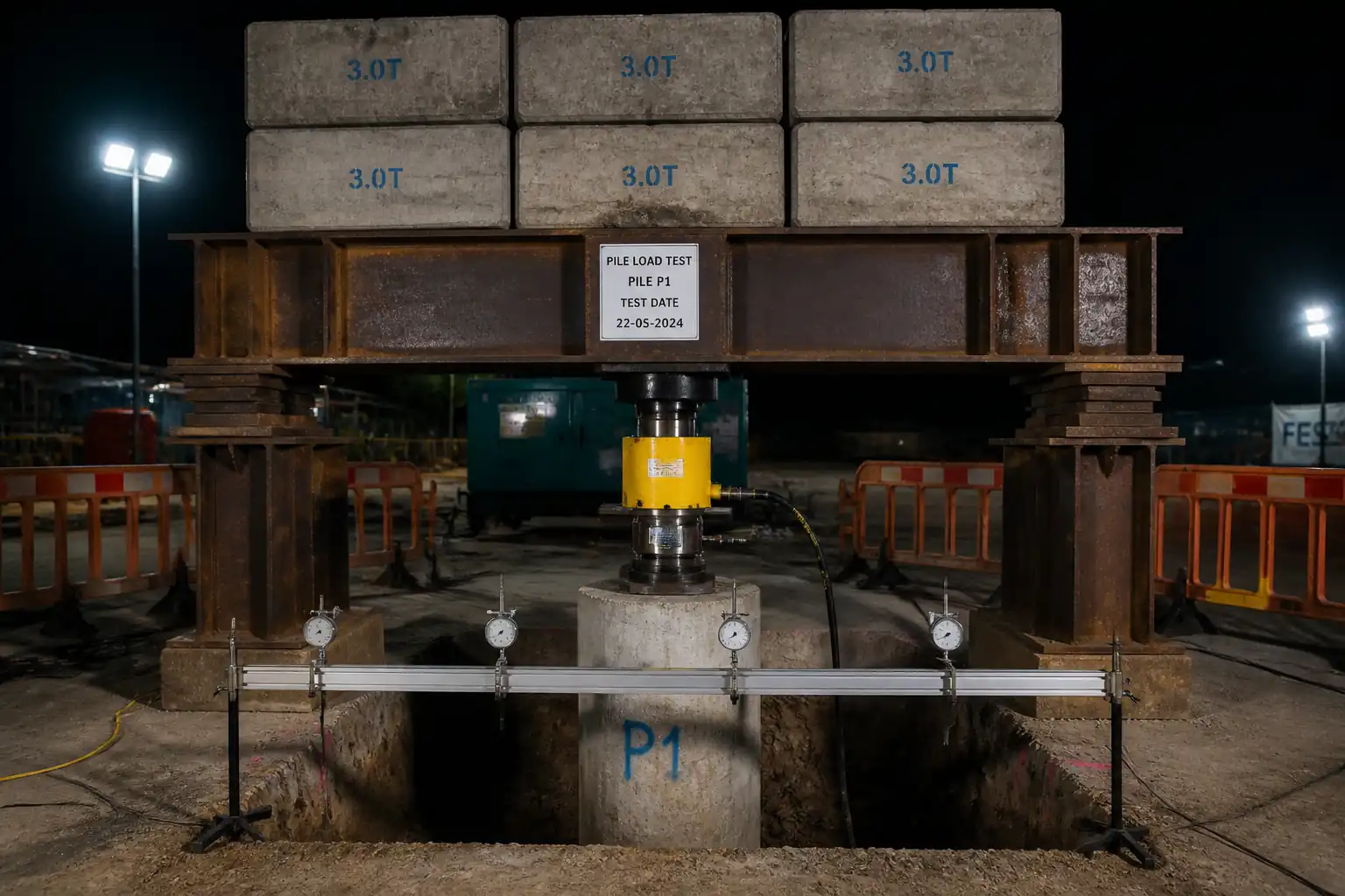
- Static load testing (maintained or rapid load).
- Pile driving operations beyond the test blows, except where testing is integrated with production driving.
- Foundation design modifications (recommendations only).
Typical Deliverables
- Field PDA logs, wave-up/wave-down traces, transferred energy, measured/computed stresses.
- CAPWAP (or equivalent) signal-matching report: ultimate resistance, shaft/toe split, quake/damping.
- Recommended driving criteria or acceptance statement, where applicable [Verify per project specifications].
- As-run test locations and pile identification.
References
| Document Type | Reference / Number | Revision | Notes |
|---|---|---|---|
| ASTM D4945 – Standard Test Method for High-Strain Dynamic Testing of Piles [Latest Edition] | |||
| EN ISO 22477-4 – Geotechnical investigation and testing – Testing of geotechnical structures – Part 4: Dynamic load testing of piles | |||
| BS EN 1997-1 (Eurocode 7) – Geotechnical design – Part 1: General rules | Capacity acceptance relative to design resistance to be verified per project specifications. | ||
| FHWA NHI-16-009 / GEC 8 – Design and Construction of Driven Pile Foundations (Dynamic testing guidance) | |||
| ICE Specification for Piling and Embedded Retaining Walls (Latest Edition) – Testing sections | |||
| ISO/IEC 17025 – General requirements for the competence of testing and calibration laboratories (for sensor and instrument calibration) |
Responsibilities
| Role | Responsibility | Name / Party |
|---|---|---|
| Project Manager | Contractor’s Project Manager | Contractor |
| PDA Specialist | PDA Specialist / Dynamic Testing Engineer | Subcontractor/Testing Agency |
| Geotechnical Engineer | Senior Geotechnical Engineer | Testing Agency |
| HSE Officer | HSE Officer | Contractor |
| QA/QC Engineer | QA/QC Engineer | Contractor |
| Supervisor | Site Supervisor / Lifting Supervisor | Contractor |
| Employer’s Rep | Client’s Representative | Client |
Resources
| Resource Type | Description | Quantity | Remarks |
|---|---|---|---|
| Personnel | Lead tester | 1 | |
| Personnel | Sensor install, cable routing, DAQ support | 1-2 | |
| Personnel | Operate hammer or drop weight safely under instruction | 2-3 | |
| Personnel | Task-specific controls | 1 |
Materials
| Material | Specification / Grade | Quantity | Remarks |
|---|---|---|---|
| Epoxy adhesive | Shear strength ≥12 MPa; pot life per ambient; manufacturer certificate [Verify per project specifications] | Gel time suitable for ambient conditions | |
| Stainless steel studs M6–M8 | Grade A2/A4; embedment as per manufacturer | ||
| Plywood/composite cushion | Thickness typically 50–125 mm; change if stress > limits [Verify per project specifications] | ||
| Spiral wrap/UV tape & junction boxes | IP65+ for boxes; UV-resistant |
Equipment
| Equipment | Capacity / Type | Quantity | Inspection Required |
|---|---|---|---|
| PDA (e.g., PDI PDA-8G or equivalent) | 1 set | ||
| Axial strain sensors | 2 | ||
| ±50 g (typ.) high-sensitivity | 2 | ||
| Diesel/air/ hydraulic hammer or drop weight 10–80 kN [Verify] | 1 | ||
| 3–5 kVA generator; tools per mounting method | As req'd | ||
| Capacity per lift plan [Verify] | As req'd |
Prerequisites
- Approvals: Method Statement and ITP approved; risk assessment and permit-to-work (PTW) in place [Verify per project HSE plan and local regulations].
- Submittals: Instrument calibration certificates (≤12 months old), technician qualifications, software versions, lift plan, hammer data sheets.
- Pile information: Pile ID, type, cross-section, length, as-built cut-off level, concrete strength (test cylinders/cores), steel grade; driving record (if driven), previous test results (if any).
- Access: Stable working platform (bearing capacity verified), exclusion zone layout, lighting for night works.
- Services: Underground/overhead utility survey and permits, proximity to structures monitored if required.
- Environmental: Noise/vibration consent limits, working hours, receptors identified.
- Pile head: Exposed, sound, flat and clean; reinforcement/steel head accessible for mounting; minimum 2–3 pile diameters of uniform section below sensor elevation [Verify per standard].
- Weather: Dry mounting window for adhesive curing; wind limits for lifting per lift plan.
- Communication: Radio protocol established between PDA specialist and hammer crew.
- Emergency: First aid, spill kit, rescue plan.
Method Sequence
| Step | Activity | Description | Responsibility | Inspection / Hold Point |
|---|---|---|---|---|
| 1 | Site induction and pre-start meeting | Conduct toolbox talk on PDA-specific hazards, roles, communication, and exclusion zones. | HSE Officer / PDA Specialist | Briefing attendance check |
| 2 | Verify submittals and calibrations | Check calibration stickers and certificates for PDA, sensors, accelerometers, and hammer energy gauge (if applicable). | QA/QC Engineer | Document check |
| 3 | Pile head preparation | Grind/level head to flatness; remove laitance/loose material; ensure sound concrete/steel. Mark sensor elevation (typically 1.5–2.0 pile diameters below head; for steel H-pile near head flange) [Verify per standard and pile type]. | Site Supervisor | Visual & straightedge |
| 4 | Install sensor mounts | Drill/cut anchors or bond plates; clean holes with oil-free air; apply epoxy per manufacturer (mix ratio, curing time). Install studs/plates to required torque after cure. | PDA Technician | Adhesive batch/time log |
| 5 | Attach sensors (2 strain + 2 accelerometers) | Attach opposite each other (180°), same elevation; align sensor axes with pile axis; secure cables with strain relief and protection; label channels. | PDA Technician | Visual alignment |
| 6 | System functional checks | Zero/balance channels; verify sampling rate (≥20 kHz recommended) and filter settings; confirm time synchronization; dry-run capture. | PDA Specialist | DAQ settings review |
| 7 | Set impact device and energy control | Align hammer/drop weight centrally; for concrete, fit appropriate helmet and cushion; set target drop height/hammer setting. Establish incremental energy plan to keep stresses within limits. | Hammer Operator / PDA Specialist | Energy setting confirmation |
| 8 | Conduct test blows – initial series | Apply 3–5 blows of increasing energy while monitoring transferred energy, velocity, and force; pause to review signal quality and stresses. | PDA Specialist | Live trace review |
| 9 | Stress control and protection | Adjust cushion or energy to maintain stresses below limits (e.g., steel ≤0.9 Fy compression/≤0.7 Fy tension; concrete compression ≤0.85 f'c; tension ≤ modulus of rupture) [Verify per project specifications and standards]. | PDA Specialist / Site Supervisor | Trace-derived stress check |
| 10 | Extended blows / re-strike (if specified) | If setup effects are required, re-test after wait time (typically 24–72 h in cohesive soils) [Verify]. Repeat blow series. | PDA Specialist | Schedule check |
| 11 | On-site preliminary interpretation | Compute Case Method capacity using selected Jc (typical starting values: steel ~0.10 s/ft; closed-end pipe ~0.11 s/ft; precast RC ~0.65 s/ft; bored pile ~0.70 s/ft; timber ~1.10 s/ft) [Verify per PDI guidance and project specs]. | PDA Specialist | Parameter log |
| 12 | Signal matching analysis (CAPWAP) | Import best blows; perform wave equation signal matching to obtain ultimate resistance, toe/shaft distribution, quake and damping. Target matching quality (MQ) ≥ 0.90 [Verify]. Conduct sensitivity to Jc and quake values. | Senior Geotechnical Engineer | Independent check |
| 13 | Reporting and acceptance | Issue report with plots, parameters, capacities vs. design, stress checks, recommendations (e.g., driving criteria). | PDA Specialist / Geotechnical Engineer | Client review |
| 14 | Demobilization | Remove sensors, grind flush mounts if required, make good, clear waste; data backup to project server. | Site Supervisor / PDA Technician | Area check |
Health, Safety, and Environment – Safety Controls
Task-specific Hazards and Controls
- Hazard: Impact from falling hammer/drop weight or components.
- Consequence: Severe injury/fatality.
- Engineering/Procedural Control: Designated exclusion zone sized by potential drop radius + 20%; positive retention on drop weight; secondary safety lanyard; use certified lifting gear and tag lines; lock-out of hammer when personnel at pile head.
- PPE: Helmet with chin strap, safety boots, gloves, eye protection, high-vis.
- Collective Measure: Physical barriers and spotters; only authorized personnel inside zone.
-
Inspection/Permit: Pre-use inspection of lifting gear; Lifting Plan and Permit to Lift signed.
-
Hazard: Rig/crane instability on inadequate platform.
- Consequence: Overturning, crush injuries.
- Control: Geotechnical verification of platform bearing capacity; outrigger mats; slope/level limits enforced; weather/wind thresholds.
- PPE: As above.
- Collective: Machine exclusion zones, banksman.
-
Inspection/Permit: Daily plant inspection; ground bearing certificate [Verify per project HSE plan].
-
Hazard: Struck-by from flying debris or spalling at pile head.
- Consequence: Eye/face injury.
- Control: Use correct helmet/drive cap and cushion; install debris shroud where feasible; stand clear of strike plane.
- PPE: Face shield over safety glasses.
- Collective: Barriers/screens.
-
Inspection/Permit: Pre-blow check of helmet/cushion condition.
-
Hazard: Noise >85 dB(A) during impacts.
- Consequence: Hearing loss.
- Control: Schedule limits; acoustic screens; limit blow count; maintain equipment to reduce noise.
- PPE: Class 5 ear defenders or earplugs.
- Collective: Noise monitoring at receptors when required.
-
Inspection/Permit: Noise monitoring log and compliance with permits.
-
Hazard: Vibration affecting adjacent structures/instrumentation.
- Consequence: Nuisance/damage.
- Control: Pre-condition survey; real-time vibration monitoring; adjust energy/drop height; increase set-back if required.
- PPE: N/A in addition to standard.
- Collective: Stakeholder notification.
-
Inspection/Permit: Vibration limits as per consent [Verify].
-
Hazard: Working at height on pile platforms/scaffolds.
- Consequence: Falls.
- Control: Use guarded platforms; fall arrest only where collective measures not possible; maintain three points of contact.
- PPE: Harness where required.
- Collective: Edge protection.
-
Inspection/Permit: Working at Height permit.
-
Hazard: Electrical hazards from DAQ/generator and damaged cables.
- Consequence: Shock, fire.
- Control: 110V CTE where applicable; RCD-protected circuits; cable routing and protection; PAT-tested equipment.
- PPE: Insulated gloves when required.
- Collective: Cable ramps/guards.
-
Inspection/Permit: Electrical permit/inspection records.
-
Hazard: Epoxy/adhesive exposure.
- Consequence: Dermal/respiratory irritation.
- Control: Use low-VOC products; follow SDS; mix in ventilated area; avoid skin contact.
- PPE: Nitrile gloves, goggles, disposable coveralls.
- Collective: Spill kit available.
-
Inspection/Permit: COSHH assessment [Verify per local regs].
-
Hazard: Manual handling of sensors/weights.
- Consequence: Strains/sprains.
- Control: Team lift; use small hoists; proper handling technique.
- PPE: Gloves, boots.
- Collective: Mechanical aids.
-
Inspection/Permit: Manual handling training record.
-
Hazard: Pinch points when fitting helmets/cushions.
- Consequence: Crush injuries to hands.
- Control: Use certified lifting, alignment tools; hands-off using tag lines.
- PPE: Impact-resistant gloves.
- Collective: Exclusion until secured.
- Inspection/Permit: Supervisor oversight during fit-up.
Environmental Controls
- Noise Management: Comply with consented working hours; use acoustic barriers if near receptors; continuous or attended noise monitoring where required; escalate if LAeq or Lmax exceed limits [Verify per permits].
- Vibration Management: Establish trigger/action limits; monitor during testing where sensitive structures/utilities exist; reduce energy or relocate if triggers exceeded.
- Dust Control: Wet suppression for grinding; vacuum extraction where feasible; tidy work area.
- Waste: Collect spent cushion materials, adhesive containers, grinding debris; segregate and dispose per waste management plan; retain hazardous waste manifests.
- Spills/Drips: Drip trays under generators and hydraulic plants; spill kits at point of use; refuel in designated areas.
- Light Pollution: Orient task lighting away from receptors; use shields for night works.
- Ecology/Water: Maintain minimum set-backs from watercourses; no washout to ground; prevent debris fall into water; implement silt controls if required.
Quality Assurance / Quality Control
- Standards Compliance: All testing in accordance with ASTM D4945 and/or EN ISO 22477‑4, project specifications, and approved ITP.
- Technician Competency: PDA Specialist with documented experience (≥100 tested piles recommended) [Verify per project specifications].
- Calibration: PDA unit, accelerometers, and strain transducers with valid calibration (≤12 months or per manufacturer). Hammer energy measurement devices verified.
- Sensor Installation QA: Opposite pairs at same elevation; bonding/torque per manufacturer; tap test for signal symmetry within ±10% amplitude difference; cable protection verified.
- Data Acquisition QA: Sampling rate ≥20 kHz [Verify]; correct gain/filter; pre- and post-test zero checks; at least 10 seconds of pre-trigger buffer recommended [Verify].
- Test Frequency: Typical 1–2% of production piles plus proof tests and re-strikes for setup characterization [Verify per project specifications].
- Stress Limits: Do not exceed specified dynamic stress limits for pile materials (e.g., steel ≤0.9 Fy; concrete compression ≤0.85 f'c; tensile ≤ modulus of rupture) [Verify].
- CAPWAP/Signal Matching: Use best-quality blow(s); target matching quality (MQ) ≥0.90; perform sensitivity on Jc and quake; report toe/shaft distribution.
- Case Damping Factor (Jc): Select starting Jc by pile type (benchmarks) and refine by correlation with CAPWAP and static load tests where available. Example benchmarks [Verify]:
- Steel H/pipe: ~0.10–0.12 s/ft
- Precast RC: ~0.60–0.70 s/ft
- Bored/Cast-in-place: ~0.65–0.80 s/ft
- Timber: ~1.0–1.2 s/ft
- Acceptance: Measured ultimate capacity (from CAPWAP or agreed method) ≥ required design resistance considering partial factors/resistance factors per design code [Verify].
- Records: Field logs, raw data files, calibration certificates, energy/stress summaries, CAPWAP report, final signed report retained in project QA system.
Attachments
- Sketch of sensor installation: elevations, 180° placement, cable routing.
- Manufacturer data sheets: sensors, PDA unit, hammer/drop weight, helmet/cushion.
- Calibration certificates: PDA, accelerometers, strain transducers (≤12 months).
- Pre-start checklists: platform, lifting gear, DAQ setup, HSE permits.
- Sample field log template and CAPWAP report template.
- Risk assessment and COSHH/SDS for adhesives.
- Noise/vibration monitoring plan and trigger levels.
- As-built pile schedule and identification register.
This content is a read-only public reference. Download or customize to get an editable version.
ITP preview
The first inspection activities from the linked ITP for Method Statement – High‑Strain Dynamic Pile Testing (PDA) with CAPWAP Signal Matching:
| Activity | Inspection / Test | Acceptance Criteria | Responsibility | Record |
|---|---|---|---|---|
| Pre-test submittals review | Check method, ITP, calibrations, personnel credentials | Approvals in place; valid calibrations; staff competency verified | Approved submittals pack | |
| Working platform and access | Level, bearing capacity, exclusion zones | Platform certified; access clear; barriers installed | Platform certificate; inspection log | |
| Pile head preparation | Flatness, integrity, uniform section check | Sound head; uniform section ≥2–3D below sensors | Photos; checklist |
Showing 3 of 10 inspection activities. View full ITP →
Related Inspection and Test Plan
An Inspection and Test Plan (ITP) is available for Method Statement – High‑Strain Dynamic Pile Testing (PDA) with CAPWAP Signal Matching. The ITP defines the inspection activities, acceptance criteria, hold and witness points, responsible parties, and records required to verify the work described in this method statement.
View the Method Statement – High‑Strain Dynamic Pile Testing (PDA) with CAPWAP Signal Matching ITP →Frequently asked questions
Continue with related Quollnet resources connected to this method statement.