Sheet Pile Driving Inspection is a field-ready checklist for inspectors and supervisors to verify layout, plumb, interlock sealing, cutoff levels, and to log blow counts and elevations during driven sheet pile installation.
- Verify layout, plumb, interlock sealing, cutoff levels during installation.
- Capture blow counts and elevations with calibrated tools and survey control.
- Ensure acceptance tolerances per approved project specifications and authority requirements.
- Interactive, commentable checklist with export and QR code verification.
The checklist
Pre-Driving Verification
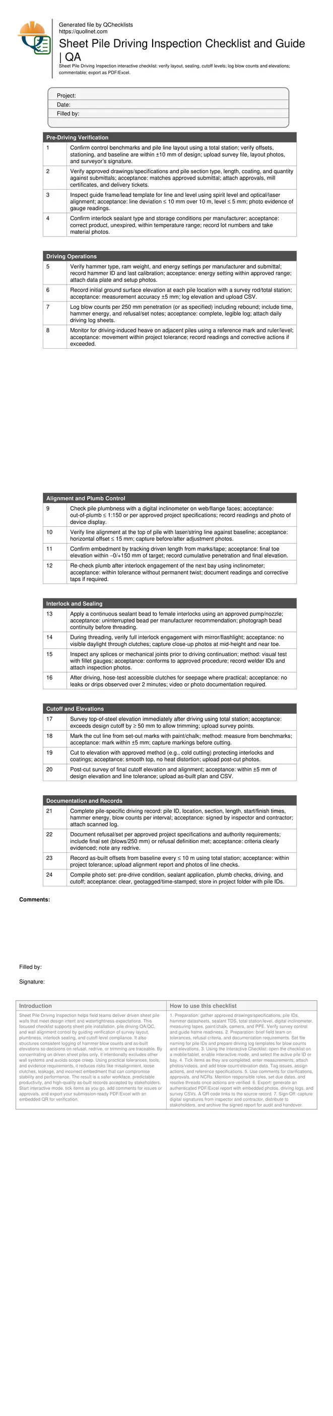
- Confirm control benchmarks and pile line layout using a total station; verify offsets, stationing, and baseline are within ±10 mm of design; upload survey file, layout photos, and surveyor’s signature.
- Verify approved drawings/specifications and pile section type, length, coating, and quantity against submittals; acceptance: matches approved submittal; attach approvals, mill certificates, and delivery tickets.
- Inspect guide frame/lead template for line and level using spirit level and optical/laser alignment; acceptance: line deviation ≤ 10 mm over 10 m, level ≤ 5 mm; photo evidence of gauge readings.
- Confirm interlock sealant type and storage conditions per manufacturer; acceptance: correct product, unexpired, within temperature range; record lot numbers and take material photos.
Driving Operations
- Verify hammer type, ram weight, and energy settings per manufacturer and submittal; record hammer ID and last calibration; acceptance: energy setting within approved range; attach data plate and setup photos.
- Record initial ground surface elevation at each pile location with a survey rod/total station; acceptance: measurement accuracy ±5 mm; log elevation and upload CSV.
- Log blow counts per 250 mm penetration (or as specified) including rebound; include time, hammer energy, and refusal/set notes; acceptance: complete, legible log; attach daily driving log sheets.
- Monitor for driving-induced heave on adjacent piles using a reference mark and ruler/level; acceptance: movement within project tolerance; record readings and corrective actions if exceeded.
Alignment and Plumb Control
- Check pile plumbness with a digital inclinometer on web/flange faces; acceptance: out-of-plumb ≤ 1:150 or per approved project specifications; record readings and photo of device display.
- Verify line alignment at the top of pile with laser/string line against baseline; acceptance: horizontal offset ≤ 15 mm; capture before/after adjustment photos.
- Confirm embedment by tracking driven length from marks/tape; acceptance: final toe elevation within −0/+150 mm of target; record cumulative penetration and final elevation.
- Re-check plumb after interlock engagement of the next bay using inclinometer; acceptance: within tolerance without permanent twist; document readings and corrective taps if required.
Interlock and Sealing
- Apply a continuous sealant bead to female interlocks using an approved pump/nozzle; acceptance: uninterrupted bead per manufacturer recommendation; photograph bead continuity before threading.
- During threading, verify full interlock engagement with mirror/flashlight; acceptance: no visible daylight through clutches; capture close-up photos at mid-height and near toe.
- Inspect any splices or mechanical joints prior to driving continuation; method: visual test with fillet gauges; acceptance: conforms to approved procedure; record welder IDs and attach inspection photos.
- After driving, hose-test accessible clutches for seepage where practical; acceptance: no leaks or drips observed over 2 minutes; video or photo documentation required.
Cutoff and Elevations
- Survey top-of-steel elevation immediately after driving using total station; acceptance: exceeds design cutoff by ≥ 50 mm to allow trimming; upload survey points.
- Mark the cut line from set-out marks with paint/chalk; method: measure from benchmarks; acceptance: mark within ±5 mm; capture markings before cutting.
- Cut to elevation with approved method (e.g., cold cutting) protecting interlocks and coatings; acceptance: smooth top, no heat distortion; upload post-cut photos.
- Post-cut survey of final cutoff elevation and alignment; acceptance: within ±5 mm of design elevation and line tolerance; upload as-built plan and CSV.
Documentation and Records
- Complete pile-specific driving record: pile ID, location, section, length, start/finish times, hammer energy, blow counts per interval; acceptance: signed by inspector and contractor; attach scanned log.
- Document refusal/set per approved project specifications and authority requirements; include final set (blows/250 mm) or refusal definition met; acceptance: criteria clearly evidenced; note any redrive.
- Record as-built offsets from baseline every ≤ 10 m using total station; acceptance: within project tolerance; upload alignment report and photos of line checks.
- Compile photo set: pre-drive condition, sealant application, plumb checks, driving, and cutoff; acceptance: clear, geotagged/time-stamped; store in project folder with pile IDs.
Preview the printable checklist
Preview page one below. Open the image or download the PDF for all pages.
At a glance
- Deliver consistent, defensible inspections for driven sheet pile walls by verifying layout control, plumbness, interlock sealing, and cutoff levels. Structured methods, tolerances, and evidence prompts reduce rework, ensure watertightness, and improve downstream activities like waling installation and backfilling, while keeping scope aligned with approved project specifications and authority requirements.
- Capture driving performance with standardized blow count logging and precise as-built elevations. Recording hammer details, energy, set, penetration, and final levels enables data-driven calls on refusal, redrive, and splice needs. Accurate records support change management, payment quantities, and long-term maintenance, preventing disputes and schedule impacts caused by undocumented variability.
- Interactive online checklist with tick, comment, and export features secured by QR code. This digital workflow attaches photos, survey files, and signatures to each item, enabling real-time collaboration between contractor, inspector, and designer, faster closeout, and authenticated archives that withstand audits and align with project handover requirements.
How to Use This Sheet Pile Driving Inspection Checklist
- Preparation: gather approved drawings/specifications, pile IDs, hammer datasheets, sealant TDS, total station/level, digital inclinometer, measuring tapes, paint/chalk, camera, and PPE. Verify survey control and guide frame readiness.
- Preparation: brief field team on tolerances, refusal criteria, and documentation requirements. Set file naming for pile IDs and prepare driving log templates for blow counts and elevations.
- Using the Interactive Checklist: open the checklist on a mobile/tablet, enable interactive mode, and select the active pile ID or bay.
- Tick items as they are completed, enter measurements, attach photos/videos, and add blow count/elevation data. Tag issues, assign actions, and reference specifications.
- Use comments for clarifications, approvals, and NCRs. Mention responsible roles, set due dates, and resolve threads once actions are verified.
- Export: generate an authenticated PDF/Excel report with embedded photos, driving logs, and survey CSVs. A QR code links to the source record.
- Sign-Off: capture digital signatures from inspector and contractor, distribute to stakeholders, and archive the signed report for audit and handover.
Layout Control and Templating for Straight, Plumb Walls
Accurate layout is the backbone of sheet pile performance. Establish robust survey control, then set the pile line with minimal offsets so the guide frame naturally enforces straightness. A rigid template/lead with true line and level prevents cumulative drift, which otherwise opens clutches and compromises watertightness. Verify the first piles meticulously; the remainder tend to follow. Measure line deviation at multiple stations and lock the guide frame before driving. Keep a dedicated survey loop for pre-drive, during-drive spot checks, and post-drive as-builts. Typical acceptance cues include horizontal offset within project tolerance (e.g., ±15 mm), level within a few millimetres, and plumbness within 1:150 or stricter if specified. Record actuals with photos of instruments and readings. If alignment slips, pause, re-square the template, and correct before continuing; driving further magnifies error, increases redrive risk, and wastes sealant.
- Fix the first bay precisely; the line will follow.
- Template must be rigid, level, and locked before driving.
- Survey at setup, spot checks, and final as-built.
- Document offsets with photos of instrument readings.
Driving Methods, Blow Count Logging, and Refusal Decisions
Driving data turns judgement calls into defendable decisions. Log blows per 250 mm (or as specified) together with hammer identification, energy setting, rebound, and time. Track the set as penetration slows; increasing blows at constant energy indicates denser layers or nearing design embedment. Combine blow counts with precise penetration depth to judge refusal or the need for redrive. Record any interruptions, splices, or equipment changes, because variations alter energy transfer and data comparability. Check for heave or movement of adjacent piles with reference marks after each bay. Inspect for damage (mushrooming, bent flanges) and correct early. Maintain clean, legible logs and upload daily. Final decisions on refusal and acceptance should align with approved project specifications and authority requirements, supported by complete logs, photos, and surveyed elevations.
- Record blows, energy, and penetration at consistent intervals.
- Survey elevations to pair with blow count trends.
- Note interruptions, splices, and equipment changes.
- Use data to justify refusal or redrive actions.
Interlock Sealing and Cutoff Level Quality Outcomes
Watertightness depends on properly sealed, fully engaged clutches. Apply a continuous sealant bead to the female interlock just before threading and confirm no gaps using a mirror and light. After driving, hose test accessible joints to spot obvious seepage. For cutoff quality, survey the top immediately after driving and trim only after confirming allowance above design elevation. Use controlled cutting methods to avoid heat distortion, burnback, or damage to coatings; grind sharp edges and keep burrs away from future wales. Post-cut, survey again to confirm final elevation and line. Document all stages with photos and embed reports in the checklist to present a complete audit trail that aligns with project specifications and handover requirements.
- Sealant bead must be continuous and compatible.
- Clutches fully engaged with no visible daylight.
- Cut above design, then trim to final elevation.
- Survey and photo-document before and after cutting.