
Method Statement – Temporary Sheet Pile Cofferdam for Bridge Pier Foundation in Water – Method Statement
AI-assisted method statement with matching ITP, PDF download, and Excel export.
More than a static template
Unlike a downloadable Word or PDF template, this method statement is an AI-assisted editable starting point connected directly to a matching Inspection and Test Plan. Every section is structured, project-adaptable, and ready to export.
- AI-assisted drafting — Customize every section with AI for your specific project scope.
- Linked ITP — A matching inspection and test plan is generated alongside the method statement.
- Multiple export formats — Download as a formatted PDF or editable Excel spreadsheet.
- Editable starting point, not a final document — Review, verify, and adjust all content against your project requirements before use.
Static template vs. Quollnet workflow
| Feature | Static template | Quollnet |
|---|---|---|
| Project-specific content | Manual fill-in required | AI-assisted customization |
| Linked ITP | Separate document, no link | Matching ITP included |
| Export formats | Usually PDF only | PDF and Excel |
| Structured sections | Free-form layout | 13 standardized sections |
| Saved to your account | Local file only | Cloud-saved, reusable |
| Content accuracy | You verify everything | AI-assisted, you still verify |
| Cost | Often free but time-intensive | Free to customize and download |
What you can customize
When you save this method statement to your account, every section becomes editable. The following 13 sections are included:
- Scope — Defines the activity and its boundaries.
- References — Standards, specifications, and drawings.
- Responsibilities — Roles and accountabilities.
- Resources — Labour, plant, and equipment summary.
- Materials — Materials and compliance requirements.
- Equipment — Tools and equipment details.
- Prerequisites — Hold points and pre-conditions.
- Method sequence — Step-by-step construction sequence.
- Safety controls — HSE risk controls and PPE.
- Environmental controls — Environmental mitigation measures.
- QA/QC — Quality inspection and test requirements.
- ITP — Inspection and Test Plan table (has its own page).
- Attachments — Referenced drawings and documentation.
Why this method statement is used
This method statement is used to define and communicate the approved procedure for carrying out method statement – temporary sheet pile cofferdam for bridge pier foundation in water on site. It ensures the work is planned in advance, the correct resources and controls are in place, and all personnel understand responsibilities, sequence, quality requirements, and safety controls before work begins. It aligns site execution with the documented scope and acceptance expectations.
Who uses this method statement
This method statement is used by contractors, site supervisors, project engineers, QA/QC engineers, HSE officers, consultants, and client representatives. It serves as a shared reference for planning, execution, supervision, inspection, and approval of the activity on site.
When it is prepared and submitted
The method statement is prepared before the work activity starts and submitted as part of the pre-construction documentation package for review and approval.
Who reviews or approves it
The method statement is usually submitted to the client representative, consultant, resident engineer, or project management consultant for review and approval before the work commences.
Important approval note
This method statement is an AI-assisted editable starting point, not a pre-approved document. Before use on any project, all content must be reviewed and approved by the relevant parties (superintendent, principal contractor, or client representative) in accordance with your contract and project quality plan.
For example: if your specification requires a departure from a referenced standard, that departure must be documented and approved separately — this method statement will not capture that automatically. Always verify against your applicable drawings, specifications, and regulatory requirements.
Method statement content
Scope
Work Summary
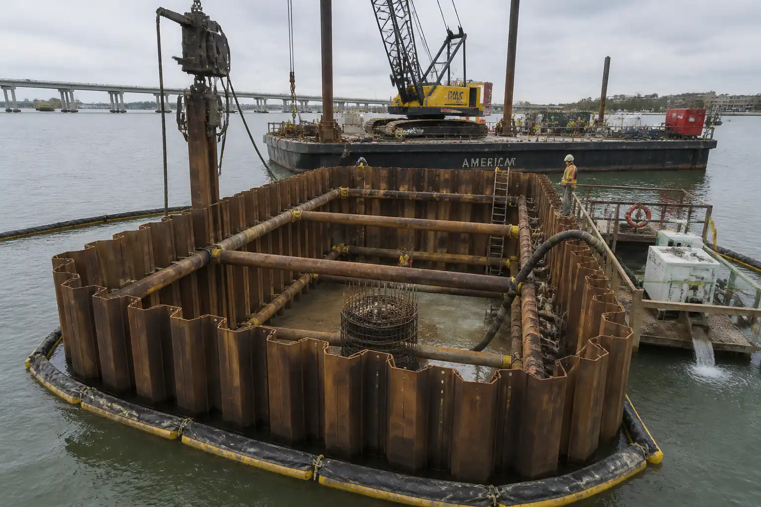
- Construct a temporary steel sheet pile cofferdam around a bridge pier foundation location in water (river/tidal), including: setting out, access/marine plant positioning, sheet pile driving (vibratory/impact), pile closure, internal walers and struts, staged excavation, underwater seal (tremie) concrete, controlled dewatering, leak sealing, monitoring (strut loads and groundwater), and handing over a dry, stable excavation to the foundation team.
Inclusions
- Marine access and mooring/spud positioning.
- Cofferdam layout using guide frames/templates.
- Interlock sealant application where specified.
- Installation of walers and hydraulic/mechanical struts; pre-load and monitoring.
- Staged excavation (dredging/GRAB) to level for seal concrete; underwater clean-up.
- Underwater seal concrete placement by tremie, curing to target strength prior to dewatering.
- Dewatering, watertightness verification, leak treatment (grouting/foam/stops).
- Instrumentation: load cells/strain gauges on struts; piezometers/observation wells; turbidity, noise, and vibration monitoring.
- QA/QC testing and ITP hold/witness points for watertightness, strut loads, and excavation stability/safe slopes.
Exclusions
- Permanent foundation construction (piles, pier shaft) beyond handover of formation.
- Utility diversions, navigation channel closures, or permanent scour protection (unless noted).
- Long-term groundwater control outside cofferdam footprint (beyond construction period).
Constraints/Assumptions
- Temporary Works Design (TWD) approved by the Engineer prior to works.
- Cofferdam geometry, strut levels, and seal thickness per TWD. Values indicated herein are typical benchmarks [Verify per project specifications].
- Environmental discharge limits, work windows, and navigation requirements apply [Verify per permits].
- Tidal/water level variations and flood events considered in method and contingency plans.
References
| Document Type | Reference / Number | Revision | Notes |
|---|---|---|---|
| Standard | BS EN 12063: Execution of special geotechnical works – Sheet pile walls [Verify edition] | ||
| Standard | EN 1997-1 (Eurocode 7) – Geotechnical design – Part 1: General rules [Verify edition] | ||
| Standard | EN 1993-5: Eurocode 3 – Design of steel structures – Piling [Verify edition] | ||
| Standard | BS EN 206 / BS 8500 (or ACI 301 & ASTM C94 for US projects) [Verify per project] | Underwater mix with anti-washout admixture per supplier TDS | |
| Guide | ACI 304R – Guide for Measuring, Mixing, Transporting, and Placing Concrete (Underwater tremie) | ||
| Guide | CIRIA guidance on cofferdams and embedded retaining walls [Verify latest applicable publication] | ||
| Standard/Guide | BS 7385-2 (Guide to damage levels from ground-borne vibration) [Verify applicability] | ||
| Regulation | Project HSE Plan; local maritime authority permits; work over water, lifting, hot works, confined space regulations [Verify per local law] |
Responsibilities
| Role | Responsibility | Name / Party |
|---|---|---|
| Project Manager | Approve method and resources; ensure permits and insurances in place | Contractor |
| Construction Manager | Implement method; ensure sequence and hold points followed | Contractor |
| Engineer/Designer | Issue IFC TWD drawings and design brief; respond to RFIs | Contractor/Designer |
| Site Engineer | Set out to tolerances; maintain as-built records | Contractor |
| Supervisor | Mooring plans, weather windows, navigational safety | Contractor |
| HSE | Task risk assessments, permits to work, emergency response | Contractor |
| QA/QC | Manage inspections, tests, materials approvals | Contractor |
| Engineer | Base heave checks, drawdown limits, review piezometer data | Contractor/Designer |
| Supervisor | Dive plans, permits, communications, emergency | Subcontractor |
| Environmental | Turbidity/noise/vibration/spill control; reporting | Contractor |
Resources (Manpower)
| Resource Type | Description | Quantity | Remarks |
|---|---|---|---|
| Personnel | Barge master, deckhands, boat operators | 8–12 [Verify per project] | |
| Personnel | Hammer operator, riggers, signalman/banksman | 6–8 | |
| Personnel | Welders, fabricators for waling/closure details | 3–5 | |
| Personnel | Tremie foreman, pump operator, QC technician | 6–8 | |
| Personnel | Pump operators, monitoring technician | 3–4 | |
| Personnel | HSE officer, environmental monitor | 2–3 |
Materials
| Material | Specification / Grade | Quantity | Remarks |
|---|---|---|---|
| Steel sheet piles | EN 10248-1/2; EN 1993-5 | As per drawings | |
| Sealant | Per TWD/Manufacturer | As required | |
| Steel | EN 10025 (S355 or as designed) | As per drawings | |
| Concrete | BS EN 206/BS 8500 or ACI 301/304R | As per TWD (thickness 0.6–1.5 m) [Verify] | |
| Sealants/grouts | Per Manufacturer | As required | |
| Silt curtain/filter media | Per supplier & Env Plan | As required |
Equipment
| Equipment | Capacity / Type | Quantity | Inspection Required |
|---|---|---|---|
| Crane barge | SWL per plan | 1–2 | |
| Vibro hammer | e.g., 1200–2400 kNm [Verify] | 1 | |
| Diesel/hydraulic impact hammer | Energy 30–120 kJ [Verify] | 1 | |
| Template | As needed | ||
| Hydraulic system | Up to design pre-load | Sets as required | |
| Diesel/electric pumps | e.g., 50–150 L/s total [Verify] | 3–6 units | |
| Instrumentation | As required | ||
| Tremie pipe & hopper | 1–2 lines | ||
| Boats | 1 safety boat + 1 workboat |
Prerequisites
- Approved IFC drawings and Temporary Works Design (cofferdam geometry, sheet pile type/length, walers/struts, pre-load values, seal concrete thickness, stability checks).
- Permits: Marine/navigation permit, environmental discharge, work over water, lifting plan approvals, hot works, confined space entry (post-dewatering), excavation permit. [Verify per project HSE plan and local regulations]
- Site investigations verified; bathymetric/hydrographic survey and current/tide data up to date (<3 months) [Verify].
- Utility/obstruction clearance completed (hydrographic/UXO if applicable) and acceptance by Engineer.
- Silt curtains/turbidity controls designed and available for installation prior to pile driving.
- Approved mix design for underwater seal concrete with anti-washout admixture; trial mix results meeting performance.
- Calibrations for load cells, pressure gauges, piezometers, flow meters, turbidity, noise, vibration meters.
- Emergency response and rescue plans for man overboard, flooding, pump failure, and pollution incidents; drill conducted.
- Weather/tide work window confirmed; mooring plan and spud leg capacity verified.
- ITP and inspection checklists issued; hold/witness points communicated to all parties; toolbox talks completed.
Method Sequence
| Step | Activity | Description | Responsibility | Inspection / Hold Point |
|---|---|---|---|---|
| 1 | Mobilization, exclusion zones, and environmental controls | Mobilize marine plant; establish navigational markers & exclusion zones; install silt curtains around work area with skirt depth ≥ 1.0–1.5 m below lowest tide [Verify]. Spill kits placed. | Construction Manager / Environmental Officer | Pre-start check and permit verification |
| 2 | Survey control & set-out | Install control points on stable reference; set out cofferdam centerline/corners using RTK/total station; verify water levels/tidal datum. | Site Engineer/Surveyor | Independent check by QA/QC |
| 3 | Guide frame/template installation | Fabricate and position pile gate/template; level and fix to barge/spuds/temporary piles. | Marine Supervisor | Level/position check |
| 4 | Material receipt & interlock preparation | Inspect sheet piles (straightness, interlocks, ID). Apply interlock sealant if specified per manufacturer TDS; protect from contamination. | QA/QC Engineer | Visual and dimensional check |
| 5 | Initial pile pitching and driving (primary panels) | Pitch first corner panels; drive using vibro to design toe minus allowance; monitor alignment with template; transition to impact hammer if refusal or set criteria reached. | Pile Driving Foreman | Driving logs; verticality checks |
| 6 | Vibration/noise monitoring during driving | Install vibration and noise monitors at agreed receptors. | Environmental Officer | Live monitoring |
| 7 | Sequential driving to full perimeter | Continue installing all piles; correct misalignment by crowding or temporary clamps; weld interlock/capping at corners/closure as designed. | Pile Driving Foreman | Line/level checks every 5–10 piles |
| 8 | Install internal walers and first strut level | Fit walers to inside face; install struts per TWD; torque/preload using hydraulic jacks. | Structural Foreman | Bolt torque/weld inspections; jack gauge checks |
| 9 | Initial internal excavation (wet) to seal level | Dredge/GRAB inside cofferdam to formation for seal concrete; tolerance for level ±50 mm; avoid undercutting piles; maintain berms as needed. | Excavation Supervisor | Bathymetric/ROV/diver check |
| 10 | Underwater cleaning and tremie set-up | Place tremie pipes to base with shoes plugged; verify reach coverage; ensure continuous concrete supply and standby agitator. | Concrete Foreman | Dry run check |
| 11 | Place underwater seal concrete (tremie) | Start pour from lowest point; maintain positive head; continuous placement to required thickness. | Concrete Foreman / QA | Slump flow/temperature testing; volume vs. theoretical |
| 12 | Curing period before dewatering | Allow seal to gain strength; minimum time/strength per design. | QA/QC Engineer | Cube/cylinder breaks at 24–72 h |
| 13 | Staged dewatering and watertightness check | Start pumps; maintain N+1 standby; monitor water level drop rate and leak points; grout/seal as needed. | Dewatering Supervisor | Piezometer readings; leak inspection |
| 14 | Lower waler/strut levels (if multi-stage) | Install additional struts per excavation stages; pre-load and lock-off. | Structural Foreman | Gauge and bolt checks |
| 15 | Excavation in the dry to formation | Excavate to final level; maintain safe slope or vertical with struts per TWD; control equipment surcharge; prepare base for inspection. | Excavation Supervisor / Geotechnical Engineer | Slope/support inspection |
| 16 | Instrumentation monitoring | Record strut loads, wall deflection (if monitored), piezometer levels; adjust pumping/struts as required. | Monitoring Technician / Engineer | Daily review |
| 17 | Handover to foundation team | Provide clean, dry, and accepted formation; issue as-built survey and records. | Construction Manager | Engineer inspection |
| 18 | Cofferdam maintenance (during foundation works) | Maintain pumps, inspect leaks/settlement, verify strut pressures daily; maintain access/egress. | Construction Manager | Daily checklist |
| 19 | Demobilization (post-permanent works) – if included | Reverse sequence: backfill/controlled flooding; remove struts/walers; extract sheet piles (if recoverable); environmental reinstatement. | Construction Manager | Post-works survey |
Health, Safety, and Environment – Safety Controls
Principal Hazards and Controls (Task-Specific)
1) Working over water / drowning
- Consequence: Drowning, hypothermia.
- Engineering/Procedural Control: Fixed guardrails on barges where practicable; lifelines; boat standby; MOB recovery kits; manned safety boat during piling/concreting; induction on MOB response.
- PPE: 150N auto-inflating PFD, anti-slip boots, gloves, helmet with chin strap.
- Collective Measure: Exclusion zones, non-slip deck surfacing, lighting for night work.
- Inspection/Permit: Daily boat and PFD checks; Marine PTW; verify per project HSE plan and local regulations.
2) Lifting and pile handling/crush points
- Consequence: Crush injuries, dropped loads.
- Control: Engineered lifting points, certified lifting gear, tag lines, dedicated banksman; weather/tide limits in lift plan.
- PPE: Hard hat with chin strap, cut-resistant gloves, safety footwear, eye protection.
- Collective: Exclusion zone under suspended loads; positive radio comms.
- Inspection/Permit: Appointed Person-approved lift plan; pre-lift checklist.
3) Pile driving vibration/noise
- Consequence: Hearing damage, nuisance, structural damage to nearby assets.
- Control: Vibro settings optimized; impact hammer only as needed; real-time PPV/noise monitoring with action limits; pre-condition survey of receptors.
- PPE: Hearing protection, gloves, eye protection.
- Collective: Acoustic shielding where feasible; inform stakeholders.
- Inspection/Permit: Environmental monitoring logs; adjust operations if limits approached.
4) Hydraulic strut pre-loading (stored energy)
- Consequence: Hose/connector failure, sudden release of energy.
- Control: Rated hoses; whip checks; barriers during jacking; step-back distance; controlled pressurization; trained operators only.
- PPE: Face shield, gloves, safety boots, long sleeves.
- Collective: Physical barriers/signage during jacking.
- Inspection/Permit: Calibration and pressure test certificates; jacking permit.
5) Confined space/engulfment post-dewatering
- Consequence: Asphyxiation, entrapment, flooding.
- Control: Confined space assessment; gas testing; emergency egress ladders; flood alarm; rescue plan; staged dewatering with standby pump.
- PPE: Gas monitor, harness if required, PFD where flood risk remains.
- Collective: Entry permit and attendant; high-level alarms on sumps.
- Inspection/Permit: Confined Space PTW; dewatering permit; daily inspections.
6) Underwater concreting (tremie) and cement exposure
- Consequence: Chemical burns, environmental release.
- Control: AWA per TDS; silt curtains; continuous tremie to avoid plume; washout in lined pits.
- PPE: Alkali-resistant gloves, goggles, coveralls.
- Collective: Dedicated washout area with containment.
- Inspection/Permit: Concrete QA checks; environmental permit conditions.
7) Hot works (welding cap plates/walers)
- Consequence: Fire, burns, fume inhalation.
- Control: Hot work permits; fire blankets; fume extraction or open-air ventilation; fire watch.
- PPE: Welding helmet, FR clothing, gloves.
- Collective: Fire extinguishers; gas cylinder segregation.
- Inspection/Permit: Hot work PTW; welder qualifications (WPS/PQR).
8) Diving operations (if used)
- Consequence: Drowning, DCI, entanglement.
- Control: IMCA/ADC compliant dive plan; comms; umbilical management; standby diver.
- PPE: Full dive PPE per dive plan.
- Collective: Exclusion of moving plant during dives; alpha flag raised.
- Inspection/Permit: Diving PTW; dive medicals/logs; verify per local regulations.
9) Excavation stability and base heave
- Consequence: Collapse, sudden inflow.
- Control: Adhere to TWD staging; monitor piezometric levels; hold point before further excavation; emergency re-flood plan.
- PPE: PFD where flood risk remains, helmets, boots.
- Collective: Barriers and exclusion; inspection after heavy rain/tide surges.
- Inspection/Permit: Excavation permit; Engineer sign-off at hold points.
10) Electrical and fuel hazards on water
- Consequence: Electrocution, fire, pollution.
- Control: IP-rated equipment; RCDs; fuel transfer procedure; drip trays; spill kits.
- PPE: Gloves, eye protection.
- Collective: Bunded fuel storage on barge.
- Inspection/Permit: Electrical inspection tags; fuel transfer permit.
11) Night works/visibility
- Consequence: Struck-by, slips/trips.
- Control: Task lighting to ≥50 lux general / ≥200 lux task [Verify]; reflective PPE; clear walkways.
- PPE: High-vis, headlamp.
- Collective: Lighting towers positioned to avoid glare.
- Inspection/Permit: Night work authorization; lighting checks.
[All measures to be verified per project HSE plan and local regulations].
Environmental Controls
- Turbidity Management: Install silt curtains before pile driving and during underwater concrete; monitor NTU upstream/downstream. Acceptance target: discharge turbidity ≤ 50 NTU above background or per permit [Verify]. Adjust works or add secondary curtain if limits approached.
- Dewatering Discharge: Route to settlement tank/bag + geotextile filter; oil-water separator if sheen observed. Maintain pH 6.5–8.5 and TSS per permit [Verify]. Sample frequency: daily during initial drawdown then weekly.
- Spill Prevention: Bunded fuel storage on barge; drip trays; designated refueling point with spill kit; trained responders. Report and clean per incident plan.
- Noise and Vibration: Real-time monitoring at receptors; adhere to work hours and limits per permit. Use vibro hammer preference; impact hammer with shrouds/cushions as feasible.
- Wildlife/Timing Windows: Adhere to in-water work windows; soft-start piling; marine fauna observers if required [Verify].
- Waste Management: Segregate scrap steel, used sealant cartridges, concrete washout; dispose via licensed carrier. No discharge of grout/sealant to water.
- Sediment/Scour: Avoid over-dredging; if scour mats/stone are temporary, retrieve post-works.
- Air Quality: Low-sulfur diesel; maintain plant to minimize smoke.
- Visual/Sheen Checks: Continuous watch during operations; stop and respond if sheen visible.
- Incident Response: Pollution control plan onboard; contact list for authorities; drills conducted monthly.
QA/QC Controls
- Submittals and Approvals: TWD calculations/drawings, mix designs, WPS/PQR, instrumentation plan, monitoring plan, lift plans, and ITP approved before start.
- Material Control: Sheet pile MTCs checked; interlock sealant TDS/batch certs; strut components with traceability; concrete supplier prequalification.
- Tolerances: Sheet pile plumbness ≤ 1:100; plan position ±50 mm; waler elevation ±10 mm; seal concrete level ±50 mm; formation level ±20 mm [Verify per TWD/spec].
- Records: Driving logs (hammer energy, blow count, refusal depth), survey reports, pre-load charts, concrete tickets, test results, dewatering logs, turbidity/noise/vibration logs.
- Testing Frequency: Concrete slump flow every truck; temperature every truck; strength: ≥ 6 specimens per pour (early-age + 28-day) [Verify]; water quality per permit; instrumentation daily or as specified.
- Hold/Witness Points: 1) Strut pre-load; 2) Seal concrete strength and authorization to dewater; 3) Watertightness acceptance; 4) Excavation formation/slope acceptance.
- Nonconformance & Corrective Action: NCR raised for misalignment, leaks, test failures; corrective measures (grouting, re-drive/auxiliary pile, additional bracing) subject to Engineer approval.
- As-Built: Final survey of cofferdam, strut levels, seal thickness (volume reconciliation), formation levels; monitoring plots included in handover dossier.
Attachments
- Temporary Works Design (cofferdam, walers/struts, seal concrete) – calculations and drawings
- Lift plans and crane barge stability/marine mooring plan
- Underwater concrete mix design, trial mix results, and supplier approvals
- WPS/PQR and welder qualifications; NDT plan (if applicable)
- Instrumentation and Monitoring Plan (load cells, piezometers, vibration/noise/turbidity)
- Environmental Management Plan; silt curtain installation drawings; discharge treatment schematics
- Permits to Work (marine, hot work, lifting, confined space, dewatering)
- Risk assessments and method-specific toolbox talks
- Calibration certificates for pumps, gauges, load cells, meters
- Emergency Response Plan (MOB, flood, pollution)
- As-built survey templates and inspection checklists
This content is a read-only public reference. Download or customize to get an editable version.
ITP preview
The first inspection activities from the linked ITP for Method Statement – Temporary Sheet Pile Cofferdam for Bridge Pier Foundation in Water:
| Activity | Inspection / Test | Acceptance Criteria | Responsibility | Record |
|---|---|---|---|---|
| Pre-construction permits and plans | Check approvals | All permits and TWD/ITP approved; exclusion/marine plans in place | PM / HSE / Marine Supervisor | Permit register, approvals |
| Sheet pile delivery inspection | Visual/dimensional | Mill certs confirmed; damage within tolerance; correct section/length | QA/QC Engineer | Receiving inspection |
| Template installation survey | Survey check | Position ±20 mm; level ±5 mm | Surveyor / QA | Survey report |
Showing 3 of 15 inspection activities. View full ITP →
Related Inspection and Test Plan
An Inspection and Test Plan (ITP) is available for Method Statement – Temporary Sheet Pile Cofferdam for Bridge Pier Foundation in Water. The ITP defines the inspection activities, acceptance criteria, hold and witness points, responsible parties, and records required to verify the work described in this method statement.
View the Method Statement – Temporary Sheet Pile Cofferdam for Bridge Pier Foundation in Water ITP →