Verify sheet pile toe level and driving criteria is a practical checklist for inspectors and engineers to confirm penetration, refusal/blows per 250 mm, obstruction handling, and complete as-built documentation.
- Confirm penetration, set, and refusal using standardized 250 mm intervals.
- Record hammer energy, verticality, and toe elevation with survey evidence.
- Handle obstructions safely with pre-boring, redrive, and approvals.
- Interactive, commentable, export-ready checklist with QR code verification.
The checklist
Pre-Drive Controls
- Review approved drawings, method statement, and criteria for penetration, refusal (blows per 250 mm), and target toe elevation per approved project specifications and authority requirements. Evidence: signed ITP checklist, marked datum benchmarks, and photo of issued-for-construction plans.
- Verify hammer type and calibrate energy using manufacturer tools or energy meter; record stroke/pressure. Acceptance: energy within manufacturer range for sheet type. Evidence: calibration certificate and daily energy readings attached to pile IDs.
- Measure each pile length and confirm splicing plan to achieve design embedment considering final cut-off. Acceptance: available length ≥ design penetration + cut-off allowance. Evidence: measurement log, heat numbers, and photos of splice preparation.
- Establish survey control for top and toe levels with total station; close traverse. Acceptance: control closure ≤ ±5 mm and benchmark protected. Evidence: survey report, control point photos, and coordinates posted in the field.
Driving Operations
- Record blow counts per 250 mm continuously with time, set per blow, and stroke/pressure. Acceptance: consistent penetration without unexplained spikes. Evidence: signed driving log with photos of chalk marks every 250 mm.
- Monitor verticality/alignment using spirit level or laser plumb at intervals. Acceptance: deviation within project tolerance (e.g., ≤ 1:100) per approved project specifications and authority requirements. Evidence: readings and photos at 1 m intervals.
- Inspect helmet seating, hammer cushion, and pile cap before each drive. Acceptance: flat, undamaged surfaces; cushion thickness within manufacturer limits. Evidence: close-up photos and supervisor sign-off per shift.
- Check interlock engagement and apply lubricant to avoid overheating. Acceptance: interlocks free, no discoloration or galling. Evidence: IR thermometer readings and maintenance log entries.
Penetration and Refusal Criteria
- Confirm minimum penetration is achieved. Acceptance: toe elevation at or below design toe level within ±0.05 m. Evidence: survey shot tied to benchmark and logged against pile ID.
- Apply refusal criteria based on blows per 250 mm at recorded energy. Acceptance: refusal when threshold per approved project specifications and authority requirements is met; note stroke/pressure. Evidence: log entries highlighting refusal interval with supervisor signature.
- If set reduces abruptly without reaching criteria, pause and assess for false set or cushion degradation. Acceptance: resume only after cause is corrected. Evidence: inspection photos and corrective action note on log.
- Adjust hammer energy incrementally to maintain safe penetration; avoid exceeding equipment or sheet limits. Acceptance: energy within manufacturer bounds and method statement. Evidence: energy trend on log and operator confirmation.
Obstructions Handling
- On sudden blow-count spikes or rebound, stop driving and mark depth. Acceptance: investigation initiated per method statement. Evidence: depth mark photo, GPS location, and notification to engineer.
- Attempt controlled extraction and redrive up to 2 m to clear debris. Acceptance: restored penetration comparable to adjacent sheets. Evidence: extraction/redrive cycles recorded with blow counts per 250 mm.
- Pre-bore with auger diameter smaller than sheet width to obstruction depth +0.5 m if required. Acceptance: spoils logged; interlocks undamaged. Evidence: bore log, photos, and approval per method statement.
- Submit obstruction treatment report detailing location, depth, and mitigation. Acceptance: engineer approval prior to resuming full driving. Evidence: signed inspection request and attached sketches/photos.
Toe Level Verification
- Survey toe depth immediately after achieving criteria using dip tape inside pan, weighted line, or sonic device. Acceptance: measurement accuracy ±10 mm. Evidence: survey sheet with instrument and benchmark references.
- Cross-check toe elevation by length accounting: delivered length − exposed length − cut-off allowance. Acceptance: discrepancy ≤ 20 mm; otherwise remeasure. Evidence: calculation sheet attached to pile record.
- Verify cut-off elevation for top-of-pile to avoid undercutting embedment. Acceptance: cut-off within ±10 mm of specified level. Evidence: marked pile photos and foreman sign-off.
- Record groundwater level at survey time to contextualize penetration performance. Acceptance: reading from piezometer or observation well. Evidence: instrument reading photo and timestamp in log.
Records and As-Builts
- Complete a driving record per sheet: location, lengths, energy, blows per 250 mm, refusal notes, toe elevation, and variances. Acceptance: record signed daily. Evidence: compiled PDF with photos and signatures.
- Attach instrument evidence: energy meter screenshots, IR temperature readings, and GPS coordinates. Acceptance: files labeled by pile ID. Evidence: uploaded images/files linked in log.
- Update as-built plan with sheet IDs, toe elevations, obstruction treatments, and refusal zones; georeference to site grid. Acceptance: CAD/DWG with revision control. Evidence: exported PDF/DWG with title block and date.
- Obtain final approvals from inspector, contractor PM, and engineer; archive in DMS with QR-linked export. Acceptance: all signatures captured. Evidence: approval workflow record and QR-authenticated file.
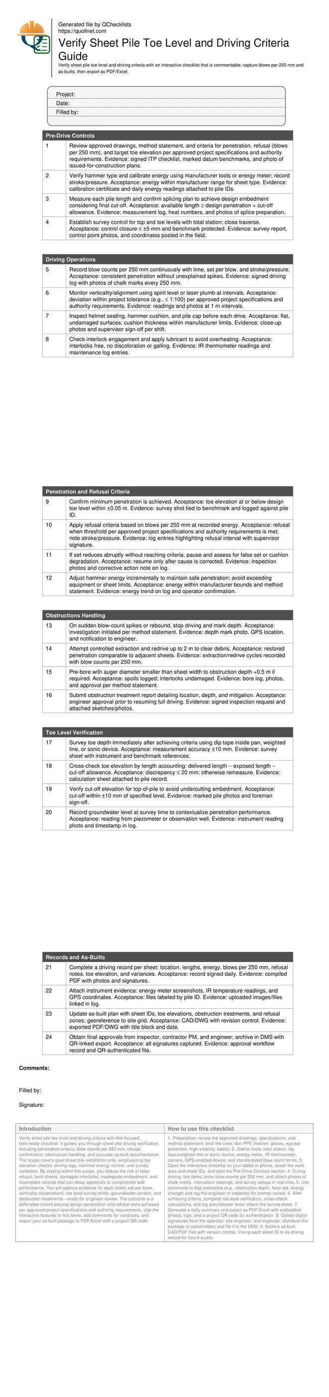
Preview the printable checklist
Preview page one below. Open the image or download the PDF for all pages.
At a glance
- Prove design embedment by linking blow counts per 250 mm with set, energy, and final toe elevation. The checklist standardizes observations, prevents false refusal, and preserves interlock integrity by guiding corrective actions when penetration stalls or obstructions are encountered.
- Streamline verification by capturing survey shots, depth checks, and computed toe elevation cross-checks against pile length and cut-off. Built-in prompts ensure tolerances are met, discrepancies are investigated immediately, and evidence is stored with each sheet’s unique ID.
- Interactive online checklist with tick, comment, and export features secured by QR code. Use it to centralize driving logs, survey shots, approvals, and photos, reducing paperwork, avoiding rework, and providing verifiable audit trails for penetration, refusal, obstructions, and toe level compliance.
- Strengthen closeout with complete as-built plans showing sheet IDs, toe elevations, refusal locations, and obstruction treatments. Digital signatures, revision control, and QR-authenticated exports deliver confidence to project managers, authorities, and future maintainers reviewing wall performance.
How to Use This Interactive Sheet Pile Driving Verification Checklist
- Preparation: review the approved drawings, specifications, and method statement; brief the crew; don PPE (helmet, gloves, eye/ear protection, high-visibility, boots).
- Gather tools: total station, dip tape/weighted line or sonic device, energy meter, IR thermometer, camera, GPS-enabled device, and standardized blow-count forms.
- Open the interactive checklist on your tablet or phone, select the work area and sheet IDs, and start the Pre-Drive Controls section.
- During driving, tick items, enter blow counts per 250 mm, and attach photos of chalk marks, instrument readings, and survey setups in real time.
- Use comments to flag anomalies (e.g., obstruction depth, false set, energy change) and tag the engineer or inspector for prompt review.
- After achieving criteria, complete toe level verification, cross-check calculations, and log groundwater level; attach the survey sheet.
- Generate a daily summary and export as PDF/Excel with embedded photos, logs, and a project QR code for authentication.
- Collect digital signatures from the operator, site engineer, and inspector; distribute the package to stakeholders and file it in the DMS.
- Archive as-built CAD/PDF files with version control, linking each sheet ID to its driving record for future audits.
Interpreting Penetration, Set, and Refusal
Driving criteria hinge on correlating blow counts per 250 mm with actual set at a documented hammer energy. Reliable logs require consistent counting, stable equipment, and awareness of false set—temporary increases in resistance from cushion degradation, loose fill, or interlock friction. Refusal must be declared only when the specified blow threshold is reached at a confirmed energy, avoiding premature calls that leave toe levels high. When penetration stalls, pause to diagnose: check helmet seating, cushion condition, stroke/pressure, and pile alignment. Adjust energy incrementally within manufacturer limits to maintain productive penetration without damaging sheets. Record any change in energy or method so acceptance decisions remain traceable. These practices create a defensible link between field effort and ground resistance, preventing under-embedment and ensuring walls perform as designed.
- Log blows per 250 mm with energy and set.
- Confirm energy before declaring refusal.
- Investigate false set before escalation.
- Adjust energy within manufacturer limits.
- Document all changes to remain traceable.
Surveying and Verifying Toe Level
Toe level verification depends on accurate measurements tied to robust control. Use a total station to set and verify benchmarks, then determine toe depth by dip tape inside the sheet pan, a weighted line, or an approved sonic device. Immediately cross-check by length accounting: delivered length minus exposed length minus cut-off allowance. Differences larger than tolerance signal measurement error, splicing variance, or driving record gaps. Capture groundwater levels to explain variable resistance. Photograph all measurement setups and record instrument references for repeatability. Maintain a clear acceptance rule: toe elevation at or below design, within the stated tolerance. These steps transform raw driving data into verifiable as-built information, ready for engineer review and later maintenance reference.
- Tie all measurements to a benchmark.
- Use two methods to cross-check toe level.
- Apply a clear tolerance for acceptance.
- Record groundwater at survey time.
- Photo-document instruments and setups.
Handling Obstructions Without Compromising Interlocks
Obstructions reveal themselves as sudden blow-count spikes, rebound, or drifting alignment. The priority is to avoid damaging interlocks or bending sheets. Stop driving, mark the depth, and notify the engineer per the method statement. Start with low-risk options: controlled extraction and redrive to clear debris. If needed, pre-bore with an auger smaller than the sheet width to the obstruction depth plus allowance, keeping the bore centered to protect interlocks. Record spoils and treatments. Resume driving at documented energy and confirm that penetration patterns match adjacent sheets. Close out with a short obstruction report including location, depth, treatment, and approvals. This measured approach preserves wall integrity and keeps records defensible.
- Pause and mark depth when spikes occur.
- Try extract–redrive before pre-boring.
- Pre-bore smaller than sheet width.
- Log spoils, depths, and approvals.
- Resume at documented energy settings.