Method Statement: Spray-Applied Cementitious Fireproofing (SFRM) to Structural Steel – Method Statement
AI-assisted method statement with matching ITP, PDF download, and Excel export.
More than a static template
Unlike a downloadable Word or PDF template, this method statement is an AI-assisted editable starting point connected directly to a matching Inspection and Test Plan. Every section is structured, project-adaptable, and ready to export.
- AI-assisted drafting — Customize every section with AI for your specific project scope.
- Linked ITP — A matching inspection and test plan is generated alongside the method statement.
- Multiple export formats — Download as a formatted PDF or editable Excel spreadsheet.
- Editable starting point, not a final document — Review, verify, and adjust all content against your project requirements before use.
Static template vs. Quollnet workflow
| Feature | Static template | Quollnet |
|---|---|---|
| Project-specific content | Manual fill-in required | AI-assisted customization |
| Linked ITP | Separate document, no link | Matching ITP included |
| Export formats | Usually PDF only | PDF and Excel |
| Structured sections | Free-form layout | 13 standardized sections |
| Saved to your account | Local file only | Cloud-saved, reusable |
| Content accuracy | You verify everything | AI-assisted, you still verify |
| Cost | Often free but time-intensive | Free to customize and download |
What you can customize
When you save this method statement to your account, every section becomes editable. The following 13 sections are included:
- Scope — Defines the activity and its boundaries.
- References — Standards, specifications, and drawings.
- Responsibilities — Roles and accountabilities.
- Resources — Labour, plant, and equipment summary.
- Materials — Materials and compliance requirements.
- Equipment — Tools and equipment details.
- Prerequisites — Hold points and pre-conditions.
- Method sequence — Step-by-step construction sequence.
- Safety controls — HSE risk controls and PPE.
- Environmental controls — Environmental mitigation measures.
- QA/QC — Quality inspection and test requirements.
- ITP — Inspection and Test Plan table (has its own page).
- Attachments — Referenced drawings and documentation.
Why this method statement is used
This method statement is used to define and communicate the approved procedure for carrying out method statement: spray-applied cementitious fireproofing (sfrm) to structural steel on site. It ensures the work is planned in advance, the correct resources and controls are in place, and all personnel understand responsibilities, sequence, quality requirements, and safety controls before work begins. It aligns site execution with the documented scope and acceptance expectations.
Who uses this method statement
This method statement is used by contractors, site supervisors, project engineers, QA/QC engineers, HSE officers, consultants, and client representatives. It serves as a shared reference for planning, execution, supervision, inspection, and approval of the activity on site.
When it is prepared and submitted
The method statement is prepared before the work activity starts and submitted as part of the pre-construction documentation package for review and approval.
Who reviews or approves it
The method statement is usually submitted to the client representative, consultant, resident engineer, or project management consultant for review and approval before the work commences.
Important approval note
This method statement is an AI-assisted editable starting point, not a pre-approved document. Before use on any project, all content must be reviewed and approved by the relevant parties (superintendent, principal contractor, or client representative) in accordance with your contract and project quality plan.
For example: if your specification requires a departure from a referenced standard, that departure must be documented and approved separately — this method statement will not capture that automatically. Always verify against your applicable drawings, specifications, and regulatory requirements.
Method statement content
Scope
Overview
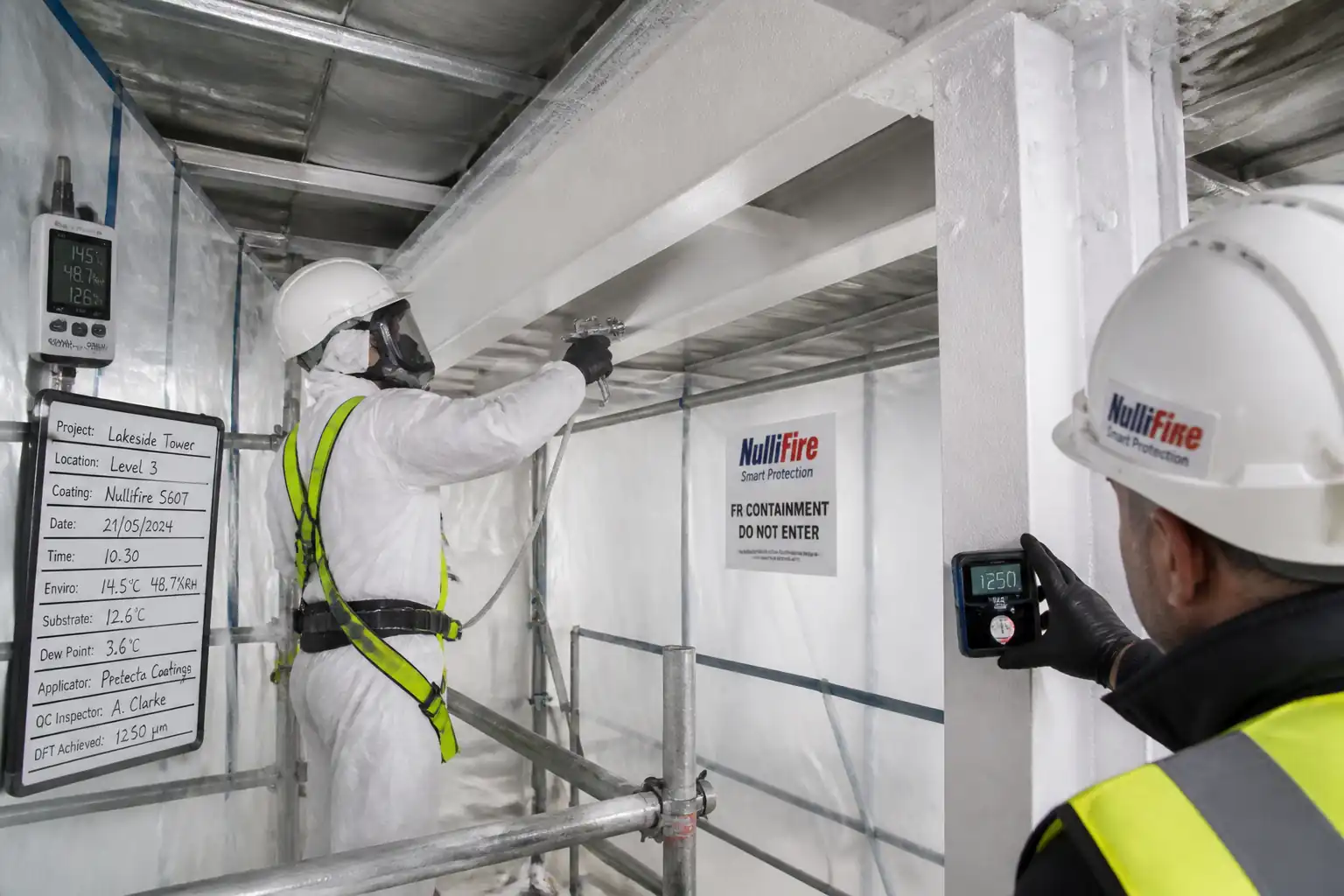
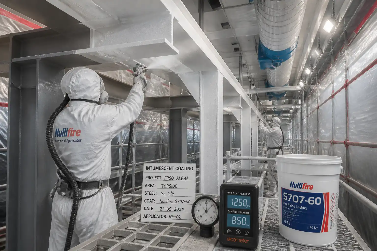
This method statement covers supply, preparation, masking, mixing, spray application, curing, repair, and quality control of spray-applied cementitious fire-resistive material (SFRM) to structural steel columns, beams, and connections. It includes work on bare or primed steel, thickness control as per the required fire-resistance rating and section factor, adhesion/cohesion testing, density checks, curing and protection, waste management, QA/QC, and final acceptance.
Extent of Work
- Structural elements: columns, beams, braces, and connections as shown on drawings.
- Fire ratings: 1–4 hours [Verify per project specifications].
- Substrates: bare steel or steel with approved compatible primer.
- Interfaces: firestopping, MEP supports, anchors, and adjacent finishes to be protected.
Exclusions
- Intumescent coatings (separate method if required).
- Acoustic/thermal insulation unrelated to fireproofing.
- Structural steel remedial works beyond minor cleaning/rust removal.
Objectives
- Achieve required fire-resistance rating using the specified SFRM and applicable UL/EN design.
- Meet quantitative tolerances for thickness, adhesion/cohesion, and density.
- Deliver compliant records and approvals for handover.
References
| Document Type | Reference / Number | Revision | Notes |
|---|---|---|---|
| Standard | ASTM E605/E605M | ||
| Standard | ASTM E736/E736M | ||
| Standard | UL 263 / ASTM E119 | Use applicable UL Design Number(s) for members [Verify per design] | |
| Reference | UL Online Certifications Directory | Use project-approved design listings | |
| Standard | BS EN 13381-4/-8 [Verify applicability] | Use where Eurocode/EN route is adopted | |
| Standard | SSPC-SP 2 / SP 3; SSPC-PA 1 | Primer compatibility to be confirmed in writing by SFRM manufacturer | |
| Standard | AISC 360 | For structural acceptance prior to SFRM | |
| Manual | Approved SFRM Manufacturer | Pre-application conference with manufacturer’s representative |
Responsibilities
| Role | Responsibility | Name / Party |
|---|---|---|
| PM | Ensure method and ITP approved; coordinate with trades | Main Contractor |
| Supervisor | Daily checks on substrate, masking, mix logs, environmental limits | Specialist Subcontractor |
| QA/QC | Verify hold/witness points; coordinate independent tests | Main Contractor |
| HSE | Ensure controls for silica dust, MEWP, hot works isolation, alarms masking | Main Contractor |
| Tech Rep | Issue compatibility letter; sign-off on mock-up | Manufacturer |
| Lab | Witness/perform tests, issue certified reports | Approved Laboratory |
| Engineer | Approve ITP, mock-up, and final works | Engineer/Client |
Resources
| Resource Type | Description | Quantity | Remarks |
|---|---|---|---|
| Manpower | Skilled nozzlemen for SFRM | As scheduled | |
| Manpower | Controls water ratio, mixing time, pump speed | 1 per pump | |
| Manpower | Masking, material handling, housekeeping | 2–6 [Verify] | |
| Manpower | Access provision and safe operation | As required |
Materials
| Material | Specification / Grade | Quantity | Remarks |
|---|---|---|---|
| SFRM | Per BOQ + 5% waste [Verify] | ||
| Bonding agent | As needed | ||
| Primer | |||
| Water | Per mix ratio | ||
| Masking | As required |
Equipment
| Equipment | Capacity / Type | Quantity | Inspection Required |
|---|---|---|---|
| Mixer/Pump | Output 20–60 L/min [Verify] | 1–2 units [Verify] | Yes |
| Compressor | 5–10 m³/min at 0.5–0.7 MPa [Verify] | 1 | Yes |
| Spray set | As required | Yes | |
| Gauges | 2+ | Yes | |
| Pull tester | 1 | Yes | |
| Core kit + oven | As needed | Yes | |
| Scaffold/MEWP | As needed | Yes | |
| HEPA vacs | As needed | Yes |
Prerequisites
Approvals and Submittals
- Product data sheets, SDS, UL/EN design listings, primer compatibility letter, method statement, and ITP approved.
- Mix design and water ratio per manufacturer; equipment calibration certificates available.
Site Readiness
- Structural steel inspected and released by Engineer; all welding/bolting complete; surfaces accessible.
- Ambient/substrate conditions within manufacturer limits: typically 4–43°C, RH < 85%, no condensation (substrate ≥ 3°C above dew point) [Verify per TDS].
- Power, water, compressed air available and safe; lighting ≥ 200 lux at workface [Verify].
Mock-Up
- Construct representative mock-up (min 1.0 m x 1.0 m including primed member) to demonstrate finish, thickness control, and testing. Obtain written approval prior to production.
Interfaces/Protection
- Mask adjacent finishes, equipment, and fire detectors; isolate/suppress alarms as approved by Client/Facility [Verify per HSE plan].
- Access (scaffold/MEWP) inspected and tagged valid for use.
Training & Permits
- Applicators trained/experienced on specified SFRM; toolbox talk completed.
- Permits in place: Hot work isolation (if any), MEWP operation, working at height, and dust/ventilation controls [Verify per local regulations].
Method Sequence
| Step | Activity | Description | Responsibility | Inspection / Hold Point |
|---|---|---|---|---|
| 1 | Pre-Start Coordination and Layout | Review drawings/UL-EN designs; identify members, W/D (Hp/A) ratios, required thickness; mark member IDs and thickness targets. | Fireproofing Supervisor / QA/QC | Hold Point HP-0: Pre-start meeting sign-off |
| 2 | Substrate Inspection & Prep | Check steel is clean, dry, free of oil, laitance, loose rust/scale; remove contaminants (SSPC-SP 2/3). Treat local rust. Ensure primer is fully cured and sound; verify DFT if required. | QA/QC Engineer / Supervisor | Hold Point HP-1: Substrate and primer readiness |
| 3 | Primer Compatibility Confirmation | Obtain written confirmation from SFRM manufacturer for existing/shop primer. If required, apply approved bonding agent per TDS and allow to cure. | Manufacturer Rep / Supervisor | Hold Point HP-2: Compatibility letter/bonding agent approval |
| 4 | Masking and Protection | Install plastic sheeting, tapes, boards to protect adjacent finishes, floors, equipment, and MEP. Bag/cover detectors or isolate alarms as approved. | Supervisor / HSE | Witness Point W-1: Protection in place |
| 5 | Mixing and Pump Setup | Set calibrated water meter; mix SFRM per bag manufacturer ratio and time (e.g., 2.5–4.5 L/kg; mix 2–4 min) [Verify per product]. Avoid over-watering. Maintain continuous feed to pump; perform slump/consistency check if required by TDS. | Pump Operator | Witness Point W-2: First batch verification |
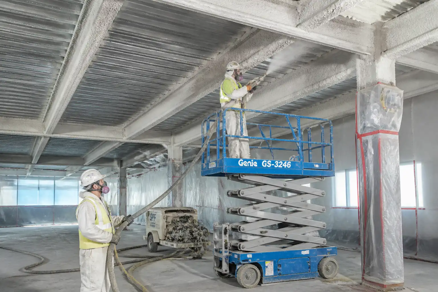
| 6 | Spray Application - First Pass | Hold nozzle 0.6–1.0 m from substrate; apply at 90° to surface; build to 10–15 mm per pass [Verify]. Encapsulate flanges and webs evenly, starting with flanges’ edges then webs to reduce rebound. | Applicator | In-process check by Supervisor |
| 7 | Interpass Set and Additional Coats | Allow initial set per TDS (typically 30–90 min) before subsequent passes. Lightly score surface if required to enhance key between coats. Continue until near-target build is achieved. | Applicator/Supervisor | In-process |
| 8 | Detailing at Connections and Penetrations | Hand-apply at bolts, stiffeners, hangers; ensure full encapsulation without bridging. Maintain specified clearances for future MEP works. | Applicator | In-process |
| 9 | Initial Thickness Checks | After sufficient set, measure thickness using pin gauge at grid spacing (typ. min 1 reading per m² or per member face; ≥ 10 readings per member set) [Verify]. Adjust with additional spray where deficient. | QA/QC / Supervisor | Witness Point W-3: First area thickness sampling |
| 10 | Curing and Protection | Protect from impact, vibration, rain, water spray, and freezing for minimum 24–72 h [Verify]. Provide ventilation to aid drying; prevent rapid desiccation. Maintain temperature and RH within TDS limits. | Supervisor | Routine HSE/QA checks |
| 11 | Adhesion/Cohesion Testing | Conduct ASTM E736 tests on set material using 50 mm dollies. Frequency: min 1 test per 930 m² (10,000 ft²) per floor/area per substrate/primer condition per day [Verify]. Additional tests at changes in primer/product/environment. | QA/QC / Independent Lab | Hold Point HP-3: Adhesion test witnessing |
| 12 | Density Sampling | Extract field cores for density per ASTM E605. Frequency: min 1 sample per 465 m² (5,000 ft²) per product per day or as specified [Verify]. Oven-dry to constant mass at 110 ± 5°C. | Independent Lab / QA/QC | Witness Point W-4: Core extraction |
| 13 | Repairs and Deficiency Closure | Address thin areas, damage, or test failures by re-prep, re-application, and re-testing as required. Feather and blend repairs. | Supervisor / QA/QC | Follow-up inspections |
| 14 | Final Inspection and Acceptance | Complete 100% visual check; verify thickness dataset coverage, adhesion/density tests, curing complete, protection removed, area cleaned. Submit as-built thickness maps and test certificates. | QA/QC / Engineer | Hold Point HP-4: Final acceptance inspection |
Health, Safety and Environment (HSE) - Safety Controls
Task-Specific Hazards and Controls
- Hazard: Working at height (scaffolds/MEWPs)
- Likely consequence: Falls causing serious injury/fatality
- Engineering/procedural control: Certified scaffold with guardrails; MEWP with pre-use checks and exclusion zone; maintain 3-point contact and platform load limits; tie-off where required; rescue plan
- Required PPE: Full body harness with lanyard (in MEWP if manufacturer requires), hard hat, safety boots
- Collective preventive measure: Edge protection, toe boards, properly decked platforms
-
Inspection/permit/supervision: Daily scaffold tag checks by competent person; MEWP operator license; PTW for MEWP; supervisor oversight
-
Hazard: Respirable dust (cementitious product, possible crystalline silica)
- Likely consequence: Respiratory irritation, silicosis (chronic), eye injury
- Engineering/procedural control: Use pre-bagged materials; mix in enclosed/ventilated area; local exhaust ventilation; wet methods to suppress dust; HEPA vacuums; minimize drop heights; sealed waste bags
- Required PPE: Tight-fitting RPE (P100/FFP3), goggles/face shield, gloves
- Collective preventive measure: Dust screens around mixing; directional ventilation
-
Inspection/permit/supervision: Air monitoring if required; RPE fit-test records; [Verify per project HSE plan and local regulations]
-
Hazard: Caustic exposure (wet cement)
- Likely consequence: Skin/eye burns, dermatitis
- Engineering/procedural control: Avoid skin contact; use mixing guards; provide eyewash and clean water; immediate decontamination procedure
- Required PPE: Alkali-resistant gloves, long sleeves, goggles/face shield, impervious apron at mixing
- Collective preventive measure: Spill kits and wash stations in mixing zone
-
Inspection/permit/supervision: HSE checks; SDS available
-
Hazard: Compressed air and pressurized hoses
- Likely consequence: Hose whip, injection injury, impact
- Engineering/procedural control: Secure hose couplings with safety clips/whips; pressure within OEM limits; depressurize before maintenance
- Required PPE: Gloves, eye/face protection, safety boots
- Collective preventive measure: Barriers around pump/hoses; clear routing to avoid trip hazards
-
Inspection/permit/supervision: Pre-start equipment checklist; competent operator
-
Hazard: Manual handling of 20–30 kg bags
- Likely consequence: Strains, musculoskeletal injury
- Engineering/procedural control: Use mechanical aids, team lifts, staging at waist height; rotate tasks
- Required PPE: Back support as needed, gloves, boots
- Collective preventive measure: Palletized deliveries close to point-of-use
-
Inspection/permit/supervision: Manual handling training verification
-
Hazard: Overspray onto live equipment/fire detectors
- Likely consequence: Damage, false alarms, service disruption
- Engineering/procedural control: Masking and isolation per permit; protective enclosures; signage
- Required PPE: Standard site PPE plus goggles during spraying
- Collective preventive measure: Area segregation and covers
-
Inspection/permit/supervision: Permit/authorization from facility; pre- and post-works checks
-
Hazard: Noise from compressor/pumps
- Likely consequence: Hearing damage
- Engineering/procedural control: Use quieter equipment; position away from personnel; limit exposure time
- Required PPE: Hearing protection (earplugs/muffs)
- Collective preventive measure: Noise barriers where feasible
-
Inspection/permit/supervision: Noise surveys where required
-
Hazard: Fire alarm isolation or hot works nearby
- Likely consequence: Uncontrolled fire risk or missed detection
- Engineering/procedural control: Approved isolation plan and fire watch; no ignition sources near dust clouds
- Required PPE: Standard PPE
- Collective preventive measure: Temporary detection heads/covers; fire extinguishers at workface
-
Inspection/permit/supervision: Permit to work; coordination with facility; [Verify per local regulations]
-
Hazard: Falling objects (tools/materials from height)
- Likely consequence: Head injury to people below
- Engineering/procedural control: Tool lanyards, debris nets, exclusion zones below work area
- Required PPE: Hard hats, safety footwear
- Collective preventive measure: Barricading and spotters
- Inspection/permit/supervision: Supervisor to enforce exclusion zone
Emergency Preparedness
- First aid kit, eyewash station at mixing zone; spill kits for slurry.
- Emergency contacts posted; rescue plan for MEWP/scaffold incidents.
- Fire extinguishers (ABC) within 15 m of workface [Verify per HSE plan].
Environmental Controls
Controls
- Dust and Overspray
- Install temporary enclosures and dust screens around mixing and spray zones.
- Use LEV/HEPA extraction; avoid spraying in high winds; schedule during low-traffic periods.
-
Cover drains and sensitive equipment; remove masking carefully to prevent debris release.
-
Washout/Slurry and Water Management
- Establish lined, bunded mixing/washout area; collect water and allow solids to settle.
-
Adjust pH before discharge; dispose via licensed waste contractor [Verify per local regulations].
-
Waste Segregation
- Segregate clean empty bags for recycling where permitted; double-bag contaminated waste.
-
Maintain waste transfer notes and manifests.
-
Noise and Vibration
-
Position compressors away from receptors; use acoustic shields where needed; restrict hours per permit.
-
Materials and Storage
-
Store SFRM bags off ground, dry, covered; rotate stock (FIFO); protect from moisture ingress.
-
Spill Prevention
-
Keep spill kits at mixing station; immediate containment and cleanup of leaks.
-
Energy and Air
-
Shut down idle equipment; maintain engines to reduce emissions; no unnecessary idling.
-
Monitoring
- Environmental log: temperature, RH, wind (if external), dust observations, noise complaints; corrective actions recorded.
Quality Assurance and Quality Control (QA/QC)
QA/QC Plan
- Submittals: Product approvals, UL/EN design numbers, primer compatibility letter, method statement, ITP, calibration certificates.
- Mock-Up: Demonstrate finish, build strategy, and pass adhesion/density benchmarks prior to production.
- Identification/Traceability: Record bag batch/lot numbers per work area and date.
Measurements and Frequencies
- Thickness (ASTM E605 field): Grid-based checks; typical minimum 1 reading per m² or per member face with ≥10 readings per member group; increase frequency at complex connections [Verify per spec].
- Adhesion/Cohesion (ASTM E736): Min 1 test per 930 m² (10,000 ft²) per floor/area per substrate condition per day; additional after failures/changes [Verify].
- Density (ASTM E605): Min 1 sample per 465 m² (5,000 ft²) per product per day [Verify].
- Environmental: Record ambient and substrate temperature, RH, and dew point each shift and when conditions change.
Acceptance Criteria
- Thickness: Average thickness per area/member ≥ specified by UL/EN design for the W/D (Hp/A); no single reading < 85–90% of specified [Verify per project].
- Adhesion/Cohesion: ≥ value specified by manufacturer/project. Typical benchmark ≥ 150 psf (≈7.2 kPa). Failure mode preferably cohesive within SFRM [Verify].
- Density: Within product-specified range (e.g., 240–640 kg/m³) and within tolerance (commonly ±15%) [Verify].
- Visual: Uniform appearance; no delamination, cracking, spalls, voids, or uncoated areas.
Documentation
- Daily reports, mixing logs (water ratio/time), batch numbers, calibration records, IRs, test reports, as-built thickness maps, NCR/CAR and closures.
- Handover dossier: Approved ITP, test certificates, compatibility letters, UL/EN design schedules, O&M instructions.
Attachments
- Approved product technical data sheets (TDS) and Safety Data Sheets (SDS)
- UL/EN design listings with required thickness vs W/D (Hp/A)
- Primer compatibility letter from SFRM manufacturer
- Mix logs, calibration certificates (pump, water meter, gauges, pull tester, oven)
- Environmental monitoring logs and dew point calculations
- Mock-up approvals and test reports (ASTM E605/E736)
- Daily inspection reports, thickness maps, and photo records
- NCR/CAR (if any) and closeout evidence
- Training, licenses, and permits (MEWP, scaffold tags, PTWs)
- Handover package index and sign-offs
This content is a read-only public reference. Download or customize to get an editable version.
ITP preview
The first inspection activities from the linked ITP for Method Statement: Spray-Applied Cementitious Fireproofing (SFRM) to Structural Steel:
| Activity | Inspection / Test | Acceptance Criteria | Responsibility | Record |
|---|---|---|---|---|
| Pre-start Review and Design Thickness Schedule | Document review of UL/EN design mapping to members and required thickness | Schedule approved; W/D (Hp/A) basis recorded [Verify] | Contractor QA/QC / Engineer | Approved schedule, minutes |
| Substrate and Primer Readiness (HP-1) | Visual cleanliness; dryness; primer condition; dew point check | Clean, dry, sound; Tsubstrate ≥ Tdew+3°C [Verify] | QA/QC / Engineer | IR with photos |
| Primer Compatibility/Bonding Agent (HP-2) | Review compatibility letter; verify bonding agent application (if required) | Written confirmation; bonding agent per TDS | Manufacturer Rep / QA/QC / Engineer | Letter, TDS, application log |
Showing 3 of 10 inspection activities. View full ITP →
Related Inspection and Test Plan
An Inspection and Test Plan (ITP) is available for Method Statement: Spray-Applied Cementitious Fireproofing (SFRM) to Structural Steel. The ITP defines the inspection activities, acceptance criteria, hold and witness points, responsible parties, and records required to verify the work described in this method statement.
View the Method Statement: Spray-Applied Cementitious Fireproofing (SFRM) to Structural Steel ITP →Frequently asked questions
Continue with related Quollnet resources connected to this method statement.