Method Statement
Method Statement – Intumescent Paint Application to Structural Steelwork
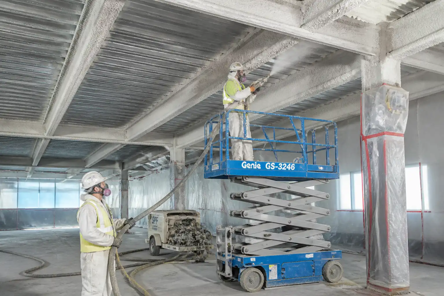
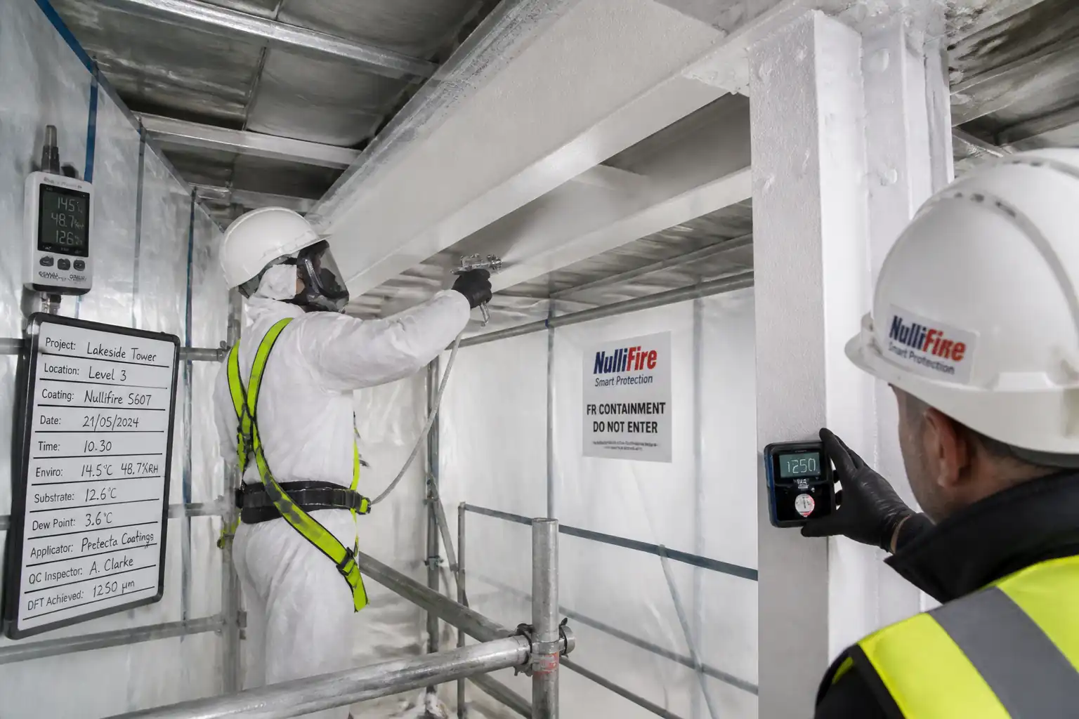
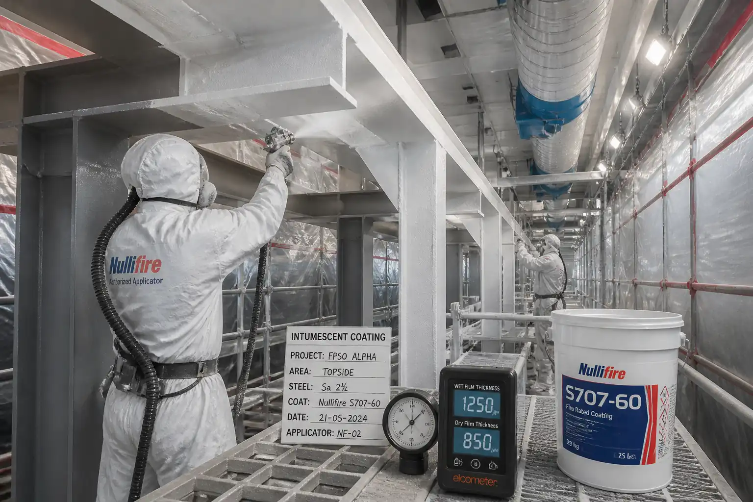
Contract method for surface preparation to Sa 2½, compatible priming, application of intumescent coatings with WFT/DFT control, stripe coats, environmental constraints, topcoat compatibility, curing, adhesion testing, and QA/QC documentation for structural steel fire protection works. [Verify per project specifications]","method_date":"2026-06-11","project_name":"","submitted_by":"","submitted_to":""},"method_json":{"version":"1.0","sections":[{"key":"scope","title":"Scope of Works","type":"textarea","content":"### Overview\nThis method covers the complete process for application of intumescent paint systems to structural steelwork, including: surface preparation to Sa 2½; verification of surface profile and contamination; compatible primer application; intumescent basecoat application with wet film and dry film thickness (WFT/DFT) control; stripe coats to edges, welds, and bolt arrays; environmental monitoring; curing; adhesion testing; topcoat/sealer application; repair of defects; and QA/QC records.\n\n### Included Elements\n- Primary and secondary structural steel members (beams, columns, braces, trusses, plate girders, connections).\n- Shop or site application (as specified).\n- Protection to achieve the fire resistance rating per the Fire Engineering design and manufacturer’s calculations.\n\n### Exclusions\n- Passive fire protection by boards, spray plasters, or cementitious systems.\n- Structural repairs or alterations to steelwork.\n\n### Key Objectives\n- Achieve the specified fire rating with verified intumescent DFT per member based on section factor (Hp/A) and exposure type.\n- Deliver a coating system free from runs, sags, pinholes, cracks, and contamination, with documented traceability and inspection records.","rows":[]},{"key":"references","title":"References and Standards","type":"table","content":"","rows":[{"reference":"ISO 8501-1: Preparation of steel substrates – Visual assessment of surface cleanliness (Sa 2½).","document_type":"Standard"},{"reference":"ISO 8502 (series): Tests for surface cleanliness – including ISO 8502-3 (dust), ISO 8502-4 (dew point), ISO 8502-6/9 (Bresle method for soluble salts).","document_type":"Standard"},{"reference":"ISO 8503 (series): Surface roughness characteristics of blast-cleaned steel substrates.","document_type":"Standard"},{"reference":"ISO 19840 / SSPC-PA 2 / ASTM D7091: Measurement of DFT on ferrous substrates (sampling and acceptance).","document_type":"Standard"},{"reference":"ASTM D4414: Measurement of wet film thickness by notch gauges.","document_type":"Standard"},{"reference":"ASTM D4541 / ISO 4624: Pull-off strength (adhesion) of coatings.","document_type":"Standard"},{"reference":"ISO 12944 (relevant parts): Corrosion protection of steel structures by protective paint systems (edge preparation, durability concepts).","document_type":"Standard"},{"reference":"SSPC-SP 1: Solvent Cleaning.","document_type":"Standard"},{"reference":"Manufacturer’s Product Data Sheets (PDS) and Safety Data Sheets (SDS) for primer, intumescent basecoat, and topcoat.","document_type":"PDS/SDS"},{"reference":"Project Specifications, Fire Strategy Report, and Intumescent Thickness Calculation Sheets per member (Hp/A, critical DFT).","document_type":"Project Document"}]},{"key":"responsibilities","title":"Responsibilities","type":"table","content":"","rows":[{"role":"Project Manager","responsibility":"Overall delivery, resources, approvals, programme integration, coordination with Fire Engineer and Architect."},{"role":"Construction/Site Engineer","responsibility":"Setting out, access/containment planning, environmental monitoring, daily interface with inspectors and applicators."},{"role":"QA/QC Manager","responsibility":"Inspection/Test coordination, ITP implementation, NCR/CAR management, records compilation, final dossier."},{"role":"Coating Inspector (AMPP/NACE Level 2 or equivalent)","responsibility":"Hold/witness inspections, surface cleanliness/profile checks, WFT/DFT verification, adhesion testing oversight, acceptance sign-off."},{"role":"Painting Supervisor","responsibility":"Execution planning, crew briefings, method adherence, mixing/application control, recoat/cure management, repairs."},{"role":"HSE Manager/Officer","responsibility":"Task-specific risk assessments, permits, ventilation, monitoring of VOC/isocyanate exposure [Verify per project HSE plan], emergency preparedness."},{"role":"Procurement/Materials Controller","responsibility":"Batch traceability, storage per PDS, shelf-life control, delivery of calibrated gauges and test kits."},{"role":"Third-Party Inspector (if specified)","responsibility":"Independent verification at hold points per ITP and contract."}]},{"key":"resources","title":"Resources (Manpower)","type":"table","content":"","rows":[{"party":"Abrasive Blasting Operators","quantity":"2–4 [Verify per scope]","remarks":"Certified, experienced with Sa 2½ requirements."},{"party":"Industrial Painters (Airless)","quantity":"3–6 [Verify]","remarks":"Qualified for intumescent systems."},{"party":"Brush/Roller Applicators (Stripe Coats)","quantity":"2–3","remarks":"Edge/weld detailers."},{"party":"Coating Inspector (AMPP/NACE L2)","quantity":"1","remarks":"Dedicated during critical holds."},{"party":"HSE Officer","quantity":"1","remarks":"Shared resource acceptable if risk profile allows."},{"party":"General Labourers/Material Handlers","quantity":"2–4","remarks":"Masking, protection, mixing support."},{"party":"Scaffolders/MEWP Operators","quantity":"As required","remarks":"Certified for work at height."}]},{"key":"materials","title":"Materials","type":"table","content":"","rows":[{"material":"Degreaser/Solvent (SSPC-SP1 compliant)","specification":"Non-residue, compatible with subsequent coating."},{"material":"Abrasive Media (e.g., Garnet 30/60)","specification":"Clean, dry, free from contaminants; profile target 40–75 µm Rz [Verify per PDS]."},{"material":"Compatible Primer (e.g., epoxy zinc phosphate or zinc-rich/epoxy as approved)","specification":"Manufacturer-approved for intumescent; typical DFT 50–75 µm [Verify]."},{"material":"Intumescent Basecoat (water-borne/solvent-borne/epoxy intumescent)","specification":"Selected to meet required fire rating; supplied with manufacturer’s thickness schedule per Hp/A [Verify]."},{"material":"Stripe Coat Material","specification":"Same intumescent basecoat or compatible primer as per manufacturer’s guidance."},{"material":"Sealer/Topcoat (if specified)","specification":"UV/weathering protection; manufacturer-approved and compatible; typical DFT 40–60 µm [Verify]."},{"material":"Thinners/Cleaners","specification":"As per PDS; controlled use only."},{"material":"Masking/Protection","specification":"Poly sheeting, tape, tarps for overspray containment."}]},{"key":"equipment","title":"Equipment","type":"table","content":"","rows":[{"equipment":"Abrasive Blasting Pot & Nozzles","capacity":"Nozzle size 6–8 mm; moisture separator and air dryer required."},{"equipment":"Air Compressor","capacity":">= 250 cfm with aftercooler/dryer [Verify]."},{"equipment":"Dust Extraction/Containment","capacity":"Vacuum recovery or enclosure with filters to control emissions."},{"equipment":"Airless Spray Pump","capacity":"45:1–68:1 ratio, min 4–6 L/min; tip 0.027–0.035 in for intumescent [Verify per PDS]."},{"equipment":"Mixers (Paddle/High-torque)","capacity":"For uniform dispersion; timer for mixing duration per PDS."},{"equipment":"Hygrometer/Dew Point Meter","capacity":"Measures air temp, RH, dew point; with calibration certificate."},{"equipment":"Infrared Thermometer/Contact Thermometer","capacity":"Substrate temperature readings."},{"equipment":"WFT Gauges (ASTM D4414)","capacity":"Notched comb type; suitable for high-build coatings."},{"equipment":"DFT Gauge (ISO 19840/ASTM D7091)","capacity":"Magnetic induction/eddy current; current calibration certificate."},{"equipment":"Bresle Kits & Conductivity Meter","capacity":"ISO 8502-6/9 soluble salt testing."},{"equipment":"Dust Tape Test Kit","capacity":"ISO 8502-3 assessment cards."},{"equipment":"Surface Profile Replica Tape/Profilometer","capacity":"ISO 8503 measurement."},{"equipment":"Access Equipment","capacity":"Certified scaffolding, MEWPs with fall protection."},{"equipment":"Ventilation/Extraction Fans","capacity":"Maintain safe solvent vapor levels and drying conditions."},{"equipment":"Lighting","capacity":"500–1000 lux in containment areas for inspection."},{"equipment":"PPE & Safety Gear","capacity":"Air-fed respirators (as needed), gloves, coveralls, eye and hearing protection."}]},{"key":"prerequisites","title":"Prerequisites","type":"textarea","content":"### Approvals and Submittals\n- Approved Method Statement, ITP, Risk Assessment/Method Statement (RAMS).\n- Manufacturer approvals: primer, intumescent, topcoat compatibility letters.\n- Fire design calculations: Hp/A, target DFT per member and fire rating, coating schedule.\n- Calibration certificates for all gauges and meters (within validity).\n\n### Site Readiness\n- Access and containment installed; ventilation plan verified.\n- Ambient condition control feasible (heating/dehumidification if required).\n- Substrate free from fabrication oils; welds inspected and accepted.\n- Edges prepared to a minimum 2 mm radius where practicable to improve coating retention [Verify per project specs/ISO 12944 guidance].\n- Protection to adjacent finishes and equipment installed.\n\n### Training & Trials\n- Toolbox talk for spraying hazards, injection injury, confined spaces, isocyanates (if applicable).\n- Mock-up/panel trial to confirm finish and achievable WFT/DFT (if specified).\n\n### Hold/Witness Points\n- Pre-blast inspection; post-blast before priming; pre-intumescent; post-DFT each coat; adhesion test; final acceptance.","rows":[]},{"key":"method_sequence","title":"Method Sequence","type":"table","content":"","rows":[{"step":"1","activity":"Receipt, Storage, and Batch Control","description":"Receive materials with COAs/SDS. Store between manufacturer’s min/max temperatures (e.g., 5–30°C) and off the floor; rotate stock FIFO. Record batch/expiry on Material Control Log.","responsibility":"Materials Controller / QA/QC","inspection":"Visual; temperature log","inspection_required":"Yes"},{"step":"2","activity":"Surface Degreasing","description":"Remove oil/grease per SSPC-SP1 using approved degreaser; rinse/wipe dry. Verify no residues.","responsibility":"Painting Supervisor","inspection":"Random wipe test/visual","inspection_required":"Yes"},{"step":"3","activity":"Abrasive Blasting to Sa 2½","description":"Blast clean to ISO 8501-1 Sa 2½ with angular profile 40–75 µm Rz [Verify per PDS]. Maintain clean, dry compressed air. Contain and collect abrasive.","responsibility":"Blasting Supervisor","inspection":"Visual comparator vs ISO 8501-1; profile measurement ISO 8503","inspection_required":"Hold Point"},{"step":"4","activity":"Surface Cleanliness Testing","description":"Check dust (ISO 8502-3, max Class 2 quantity/size [Verify]); soluble salts via Bresle (ISO 8502-6/9, ≤20 mg/m² chloride as NaCl [Verify]).","responsibility":"Coating Inspector","inspection":"Dust tape test; conductivity conversion to mg/m²","inspection_required":"Yes"},{"step":"5","activity":"Environmental Check (Pre-Prime)","description":"Record air temp, RH, dew point, steel temp. Ensure steel temp ≥ 3°C above dew point; RH ≤ 85% [Verify].","responsibility":"Coating Inspector","inspection":"Hygrometer/dew point meter","inspection_required":"Yes"},{"step":"6","activity":"Primer Application","description":"Apply compatible primer to target DFT 50–75 µm [Verify] within allowable window post-blast (typically ≤4 hours or before visible rusting).","responsibility":"Painting Supervisor","inspection":"WFT checks ASTM D4414; DFT checks per ISO 19840/ASTM D7091","inspection_required":"Witness"},{"step":"7","activity":"Primer Cure & Recoat Window","description":"Allow to cure per PDS (time/temp/RH). If exceeded recoat window, abrade/clean as per PDS before intumescent.","responsibility":"Painting Supervisor","inspection":"Time/ambient log; surface cleanliness","inspection_required":"Yes"},{"step":"8","activity":"Stripe Coats to Details","description":"Brush-apply stripe coats to edges, welds, bolt heads, stiffeners using same intumescent basecoat or as specified by manufacturer.","responsibility":"Painting Supervisor","inspection":"Visual coverage; WFT spot checks","inspection_required":"Yes"},{"step":"9","activity":"Intumescent Basecoat – First Pass","description":"Confirm target total DFT per member from approved schedule (often 1.0–3.5 mm for 60–120 min ratings) [Verify]. Apply by airless spray in multiple passes; do not exceed per-coat WFT per PDS (typ. 800–1500 µm). Avoid runs/sags.","responsibility":"Painting Supervisor","inspection":"WFT checks; visual for defects; ambient log","inspection_required":"Witness"},{"step":"10","activity":"Curing Between Coats","description":"Allow each coat to reach minimum recoat condition per PDS (time/temp/RH/ventilation). Confirm surface is firm, non-tacky, and supports subsequent coats without damage.","responsibility":"Painting Supervisor","inspection":"Touch/visual; time/ambient records","inspection_required":"Yes"},{"step":"11","activity":"Subsequent Intumescent Coats","description":"Repeat application/inspection cycles until scheduled total DFT achieved for each member. Maintain identification and mapping of readings per member/face.","responsibility":"Painting Supervisor / Coating Inspector","inspection":"DFT per ISO 19840 sampling; map and record","inspection_required":"Hold Point"},{"step":"12","activity":"Adhesion Testing (Representative Areas)","description":"Perform pull-off adhesion tests (ASTM D4541 or ISO 4624) at agreed frequency (e.g., 1 test per 500 m² or per 50 members, min 3 tests) [Verify]. Repair dollies locations after test.","responsibility":"Coating Inspector","inspection":"Pull-off tester; record MPa and failure mode","inspection_required":"Witness"},{"step":"13","activity":"Repairs and Touch-ups","description":"Address low DFT by additional coats. For runs/sags/mud cracking: sand back or remove to sound layer and reapply per PDS. Feather edges; re-measure DFT.","responsibility":"Painting Supervisor","inspection":"DFT re-check; visual finish","inspection_required":"Yes"},{"step":"14","activity":"Topcoat/Sealer (If Specified)","description":"Apply compatible sealer/topcoat within recoat window after basecoat fully cured. Typical DFT 40–60 µm [Verify]. Confirm gloss/colour if architectural.","responsibility":"Painting Supervisor","inspection":"WFT/DFT; compatibility confirmation","inspection_required":"Witness"},{"step":"15","activity":"Final Inspection and Handover","description":"Comprehensive DFT mapping, adhesion results, environmental logs, batch traceability, NCR close-outs, manufacturer’s compliance letter (if required). Protect finished works.","responsibility":"QA/QC Manager / Coating Inspector","inspection":"Document review; visual walkthrough","inspection_required":"Hold Point"}]},{"key":"safety_controls","title":"Health & Safety Controls","type":"textarea","content":"### Task-Specific Hazards and Controls\n- **Hazard:** Abrasive blasting dust and rebound.\n - **Consequence:** Respiratory injury, eye injury, silicosis (if improper media), skin lacerations.\n - **Engineering/Procedural Control:** Use low-dust garnet; enclosed/curtained blasting with dust extraction; deadman controls; trained operators; exclusion zones.\n - **PPE:** Blast hood with Grade D breathing air; gloves; cut-resistant coveralls; hearing protection; safety boots.\n - **Collective Measure:** Negative-pressure containment with filtration; debris netting.\n - **Inspection/Permit/Supervision:** Containment integrity checks; compressor moisture traps inspected daily; HSE supervision.\n\n- **Hazard:** Solvent/flammable vapors from coatings and thinners.\n - **Consequence:** Fire/explosion, toxic exposure.\n - **Engineering/Procedural Control:** Use intrinsically safe lighting/ventilation; eliminate ignition sources; decant in ventilated areas; bonding/earthing of containers; hot-work exclusion.\n - **PPE:** Chemical-resistant gloves; goggles/face shield; organic vapor respirators or air-fed respirators as required by SDS.\n - **Collective Measure:** Mechanical ventilation achieving target air changes; LEL monitoring where warranted.\n - **Inspection/Permit/Supervision:** Flammable liquids storage per approved cabinets; daily LEL/ventilation checks; permit-to-work for confined/controlled areas [Verify per project HSE plan and local regulations].\n\n- **Hazard:** Isocyanate exposure (certain polyurethane topcoats).\n - **Consequence:** Sensitization, asthma.\n - **Engineering/Procedural Control:** Substitute non-isocyanate where possible; otherwise, closed spray systems, ventilation, restricted access.\n - **PPE:** Air-fed respirator; chemical coveralls; nitrile gloves.\n - **Collective Measure:** Health surveillance/fit testing.\n - **Inspection/Permit/Supervision:** SDS review; exposure monitoring as required by law [Verify].\n\n- **Hazard:** High-pressure airless spray injection injury.\n - **Consequence:** Tissue necrosis/amputation.\n - **Engineering/Procedural Control:** Tip guards, trigger locks, safe distance, do not wipe tips under pressure; emergency response plan with immediate hospital referral.\n - **PPE:** Gloves, goggles/face shield, coveralls.\n - **Collective Measure:** Exclusion zones; equipment lockout/tagout for maintenance.\n - **Inspection/Permit/Supervision:** Daily equipment inspection; operator training records; supervisor sign-off.\n\n- **Hazard:** Working at height on steel frames.\n - **Consequence:** Falls leading to serious injury/fatality.\n - **Engineering/Procedural Control:** Certified scaffolds/MEWPs; double lanyard fall arrest; edge protection; tethered tools.\n - **PPE:** Full-body harness with shock-absorbing lanyard; helmet with chinstrap.\n - **Collective Measure:** Guardrails and toe boards; rescue plan.\n - **Inspection/Permit/Supervision:** Pre-use checks; statutory scaffold inspections; MEWP operator certification.\n\n- **Hazard:** Noise and vibration from blasting/compressors.\n - **Consequence:** Hearing loss, HAVS.\n - **Engineering/Procedural Control:** Selection of quieter plant; isolation; exposure time management.\n - **PPE:** Hearing protection (SNR per noise map).\n - **Collective Measure:** Acoustic screens where feasible.\n - **Inspection/Permit/Supervision:** Noise surveys; health surveillance per regulations.\n\n- **Hazard:** Confined/poorly ventilated spaces (enclosures).\n - **Consequence:** Asphyxiation, solvent overexposure.\n - **Engineering/Procedural Control:** Confined space assessment; forced ventilation; gas monitoring; standby attendant.\n - **PPE:** Respiratory protection per monitoring results.\n - **Collective Measure:** Permit-to-work with rescue plan.\n - **Inspection/Permit/Supervision:** Confined Space Permit; continuous monitoring.\n\n- **Hazard:** Manual handling of drums and equipment.\n - **Consequence:** Musculoskeletal injuries.\n - **Engineering/Procedural Control:** Use drum trolleys/hoists; team lifts; decant to smaller containers.\n - **PPE:** Gloves, safety footwear.\n - **Collective Measure:** Mechanical aids.\n - **Inspection/Permit/Supervision:** Supervisor to enforce lift plans.\n\n- **Hazard:** Electrical equipment in damp/paint environments.\n - **Consequence:** Electric shock.\n - **Engineering/Procedural Control:** 110V center-tapped transformers or RCDs; IP-rated equipment; cable management.\n - **PPE:** Dielectric gloves as needed; dry gloves.\n - **Collective Measure:** PAT testing.\n - **Inspection/Permit/Supervision:** Daily visual checks; formal inspections per schedule.","rows":[]},{"key":"environmental_controls","title":"Environmental Controls","type":"textarea","content":"### Controls for Environmental Impact\n- **Dust and Abrasive Containment:** Fully enclose blasting zones with sheeting; use vacuum recovery. Daily cleanup; prevent migration to drains.\n- **Waste Management:** Segregate spent abrasive and paint debris as potentially hazardous waste; test and dispose per licensed facility requirements. Maintain waste transfer notes.\n- **VOC and Odor Management:** Choose low-VOC options where feasible; mechanical ventilation to maintain concentrations below occupational limits; schedule high-VOC works off-peak.\n- **Overspray and Drift:** Use shrouds, windscreens, and correct tip/pressure; halt spraying above safe wind thresholds [Verify per site limit].\n- **Noise:** Fit silencers; schedule noisy tasks during permitted hours; provide acoustic barriers as needed.\n- **Water Protection:** Block stormwater inlets near work; deploy spill kits; prohibit washing tools into drains.\n- **Energy Efficiency:** Use properly sized compressors with dryers; shut down idling equipment.\n- **Material Efficiency:** Mix only required quantities; track pot life to reduce waste.","rows":[]},{"key":"qa_qc","title":"QA/QC Requirements","type":"textarea","content":"### Inspection and Testing\n- Implement ITP with defined hold/witness points.\n- Calibration: DFT/WFT gauges, hygrometers, conductivity meters, and pull-off testers with valid certificates.\n- Sampling Frequency (typical) [Verify per ITP/spec]:\n - DFT: per ISO 19840/SSPC-PA 2 – e.g., min 5 measurement areas per 10 m² or per member flange/web; each area = ≥3 gauge readings.\n - Salts: at least 1 Bresle test per 50 m² per shift per substrate condition change.\n - Dust: at least 1 test per 50 m².\n - Adhesion: 1 set per 500 m² or per 50 members, min 3 pulls.\n\n### Acceptance Criteria (typical – verify project/manufacturer)\n- Cleanliness: ISO 8501-1 Sa 2½, free from visible dust/oil/grease.\n- Salts: ≤20 mg/m² chloride as NaCl (Bresle) [Verify].\n- Dust: ISO 8502-3 max Class 2 (quantity/size) [Verify].\n- Profile: 40–75 µm Rz [Verify].\n- Primer DFT: 50–75 µm, uniform; within manufacturer’s limits for overcoating.\n- Environmental: Steel temp ≥3°C above dew point; RH ≤85%; substrate/application temperatures within PDS.\n- Intumescent DFT: Per approved schedule; acceptance per ISO 19840/SSPC-PA 2 – mean ≥ NDFT; no individual reading <80% NDFT unless otherwise permitted by standard/manufacturer [Verify].\n- Adhesion: ≥1.5 MPa average; no individual <1.0 MPa; predominantly cohesive failure in coating or adhesive acceptable [Verify/manufacturer].\n\n### Documentation and Traceability\n- Coating Inspection Reports (CIRs), DFT maps per member, WFT logs, environmental logs, salt/dust/profile records, adhesion test reports.\n- Batch records (primer/intumescent/topcoat), COAs/SDS, equipment calibration.\n- NCR/CARs and corrective actions; final MDR/hand-over dossier with manufacturer’s compliance letter (if required).","rows":[]},{"key":"itp","title":"Inspection and Test Plan (ITP)","type":"table","content":"","rows":[{"activity":"Material receipt and storage","inspection_test":"Verify PDS/SDS, batch numbers, shelf-life, storage temperatures","acceptance_criteria":"Conforms to approved submittals; storage within PDS limits; no damaged containers","responsibility":"QA/QC + Materials Controller","record":"Material Receipt & Storage Log"},{"activity":"Surface degreasing (pre-blast)","inspection_test":"Visual and wipe test per SSPC-SP1","acceptance_criteria":"No oil/grease residues; clean, dry surface","responsibility":"Coating Inspector","record":"Pre-blast Inspection Report"},{"activity":"Abrasive blasting","inspection_test":"Visual vs ISO 8501-1; profile ISO 8503","acceptance_criteria":"Sa 2½; profile 40–75 µm Rz [Verify]","responsibility":"Coating Inspector","record":"Post-blast Report; Profile Measurements"},{"activity":"Dust testing","inspection_test":"ISO 8502-3 dust tape test","acceptance_criteria":"Max Class 2 (quantity/size) [Verify]","responsibility":"Coating Inspector","record":"Dust Test Record"},{"activity":"Soluble salt testing","inspection_test":"ISO 8502-6/9 (Bresle), conductivity to mg/m²","acceptance_criteria":"≤20 mg/m² chloride (as NaCl) [Verify]","responsibility":"Coating Inspector","record":"Bresle Test Record"},{"activity":"Environmental conditions (pre-coating and during cure)","inspection_test":"Air/steel temp, RH, dew point","acceptance_criteria":"Steel temp ≥3°C above dew point; RH ≤85%; within PDS limits","responsibility":"Coating Inspector","record":"Environmental Log"},{"activity":"Primer application","inspection_test":"WFT (ASTM D4414) and DFT (ISO 19840/ASTM D7091)","acceptance_criteria":"Uniform primer DFT 50–75 µm [Verify]; visual free from defects","responsibility":"Coating Inspector","record":"Primer WFT/DFT Log; CIR"},{"activity":"Recoat window verification","inspection_test":"Time/ambient review; surface condition","acceptance_criteria":"Within PDS recoat interval or surface properly prepared","responsibility":"Painting Supervisor + QA/QC","record":"Recoat Verification Record"},{"activity":"Stripe coats to details","inspection_test":"Visual coverage; WFT spot checks","acceptance_criteria":"Continuous coverage on edges/welds/bolts; no misses","responsibility":"Coating Inspector","record":"Stripe Coat Inspection Record"},{"activity":"Intumescent basecoat application (each coat)","inspection_test":"WFT during spray; defects check","acceptance_criteria":"Per-coat WFT within PDS limit; no runs/sags/cracks","responsibility":"Painting Supervisor + Coating Inspector","record":"WFT Log; CIR"},{"activity":"Curing between coats","inspection_test":"Time/ambient verification; surface condition","acceptance_criteria":"Meets minimum recoat criteria per PDS; surface firm/non-tacky","responsibility":"Coating Inspector","record":"Cure Verification Log"},{"activity":"Total DFT mapping (final)","inspection_test":"DFT per ISO 19840/SSPC-PA 2 sampling plan","acceptance_criteria":"Mean ≥ NDFT; no individual <80% NDFT unless permitted [Verify]","responsibility":"Coating Inspector","record":"DFT Map & Acceptance Report"},{"activity":"Adhesion testing (representative)","inspection_test":"ASTM D4541/ISO 4624 pull-off","acceptance_criteria":"Average ≥1.5 MPa; no individual <1.0 MPa; acceptable failure mode [Verify]","responsibility":"Coating Inspector / Third-Party (if specified)","record":"Adhesion Test Report"},{"activity":"Topcoat/sealer application (if specified)","inspection_test":"WFT/DFT; compatibility check","acceptance_criteria":"Within PDS DFT; applied within recoat window; uniform finish","responsibility":"Coating Inspector","record":"Topcoat Inspection Record"},{"activity":"Final acceptance and documentation","inspection_test":"Review of MDR, close-out of NCRs, housekeeping","acceptance_criteria":"All records complete; coating free of defects; protection in place","responsibility":"QA/QC Manager + Client Rep","record":"Final Acceptance Certificate; MDR"}]},{"key":"attachments","title":"Attachments","type":"textarea","content":"- Approved product data sheets and SDS for primer/intumescent/topcoat.\n- Coating schedule by member (Hp/A, required DFT and fire rating).\n- DFT maps and WFT logs.\n- Environmental monitoring logs.\n- Bresle salt test and dust test records.\n- Surface profile measurement records.\n- Adhesion test reports with locations and photos.\n- Equipment calibration certificates.\n- Material batch and storage logs.\n- NCR/CAR register and close-out evidence.\n- Manufacturer’s compatibility/approval letters and any site visit reports.","rows":[]}],"custom_fields":[]},"method_meta":{"seo_title":"Method Statement: Intumescent Paint to Structural Steel – Sa 2½, WFT/DFT, Adhesion, Topcoat, QA/QC","meta_description":"Contract-ready method for intumescent coating of steel: Sa 2½ prep, primer, WFT/DFT control, stripe coats, curing, adhesion tests, and ITP.","keywords":["intumescent paint method","Sa 2½ surface preparation","DFT measurement ISO 19840","structural steel fire protection","adhesion testing ASTM D4541","stripe coat edges","primer compatibility","topcoat sealer","QA/QC ITP coatings","dew point control"],"ai_snippet":"This method statement details how to prepare and coat structural steel with intumescent paint, from Sa 2½ blasting to final topcoat. It defines WFT/DFT controls, curing, adhesion testing, and complete QA/QC documentation.","og_title":"Intumescent Paint Method Statement for Structural Steel","og_description":"Comprehensive, contract-ready method: Sa 2½ prep, compatible primers, WFT/DFT control, adhesion testing, curing, topcoat, and ITP for steel fire protection.","faq":[{"question":"How is the required intumescent DFT determined?","answer":"By manufacturer’s design based on each member’s section factor (Hp/A), fire rating duration, and exposure. Use the approved coating schedule and verify per project specifications."},{"question":"What environmental limits apply during application?","answer":"Typically steel temperature ≥3°C above dew point, RH ≤85%, and substrate/application temperatures within the product’s PDS. Always verify project/manufacturer limits."},{"question":"Which standards govern thickness measurements?","answer":"Use ISO 19840 or SSPC-PA 2/ASTM D7091 for DFT, and ASTM D4414 for WFT. Calibration certificates must be current."},{"question":"When should stripe coats be applied?","answer":"Before full coats on edges, welds, bolt heads, and other sharp details to ensure adequate film build and durability."},{"question":"Is adhesion testing always required?","answer":"Adhesion testing frequency is defined in the ITP or project spec. Typical practice is representative pull-off tests; verify acceptance values with the manufacturer/specifications."}]},"itp_meta":{"title":"ITP – Intumescent Coating to Structural Steel","meta_description":"Inspection and Test Plan for intumescent paint on steel: surface prep, environmental checks, WFT/DFT, adhesion, and final acceptance.","keywords":"ITP, intumescent coating, ISO 19840, SSPC-PA 2, adhesion ASTM D4541, Sa 2½, QA/QC","ai_snippet":"Defines inspections for each stage of intumescent coating works, including Sa 2½ preparation, environmental controls, WFT/DFT checks, adhesion testing, and documentation.","why_used":"To establish hold/witness points and objective acceptance criteria ensuring the coating achieves the required fire performance and durability.","who_uses_it":"QA/QC inspectors, coating supervisors, third-party inspectors, and the Client/Engineer’s Representative.","when_used":"Throughout the coating process from material receipt through final acceptance and handover.","submitted_to":"Client/Engineer for approval prior to works.","inspection_scope":"Material verification, substrate preparation, cleanliness/contamination tests, environmental monitoring, primer and intumescent application, thickness control, adhesion testing, topcoat application, and final documentation.","typical_hold_witness_points":"Post-blast inspection (Hold), pre-intumescent application (Hold), total DFT mapping (Hold), adhesion testing (Witness), final acceptance (Hold).","typical_records":"CIRs, WFT/DFT logs, environmental logs, Bresle/dust/profile results, adhesion test reports, batch logs, calibration certificates, NCR/CARs, MDR.","faq":[{"question":"What sampling plan is used for DFT checks?","answer":"Follow ISO 19840 or SSPC-PA 2: define measurement areas per member or per 10 m², with multiple gauge readings per area and mapping of results."},{"question":"How are adhesion test locations selected?","answer":"Select representative, non-critical areas agreed with the Engineer to avoid structural or aesthetic impact; repair test spots after testing."}]} ,"hero_image_prompt":"Photorealistic image of industrial painters applying white intumescent coating by airless spray to structural steel beams inside a well-lit containment with scaffolding, ventilation ducts, and inspection gauges visible; clean Sa 2½ steel and WFT/DFT tools in foreground; professional, high-resolution, neutral color grading."}
422 views
47 downloads