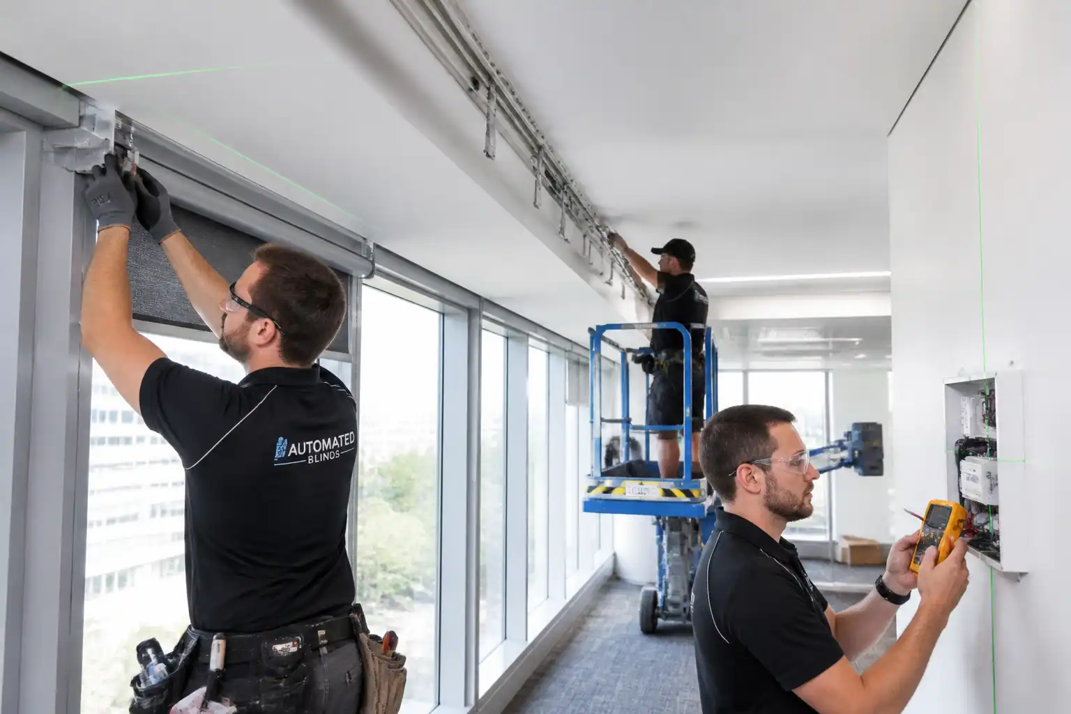

Method Statement: Installation of Internal Window Roller Blinds and Automated Motorized Curtain Tracking Systems – Method Statement
AI-assisted method statement with matching ITP, PDF download, and Excel export.
More than a static template
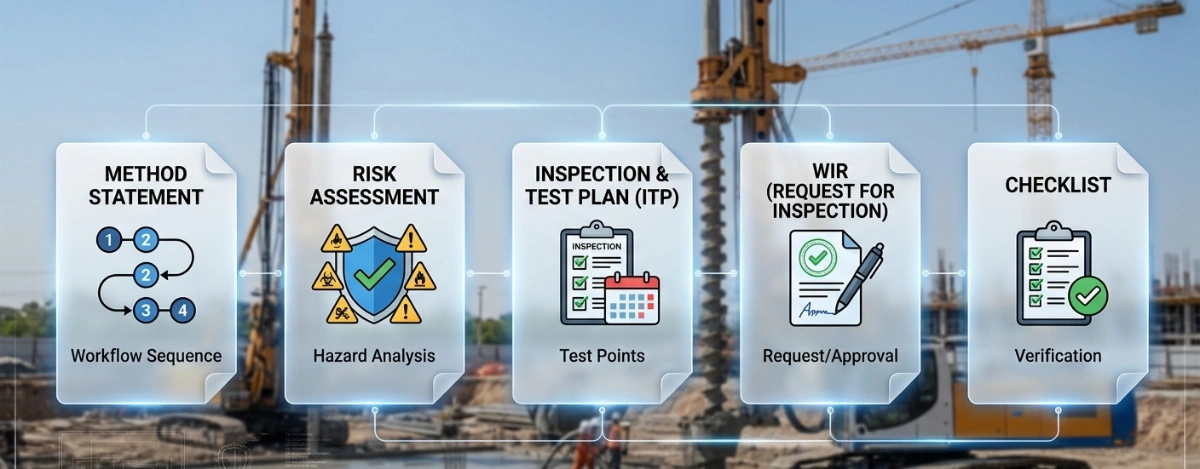
Unlike a downloadable Word or PDF template, this method statement is an AI-assisted editable starting point connected directly to a matching Inspection and Test Plan. Every section is structured, project-adaptable, and ready to export.
- AI-assisted drafting — Customize every section with AI for your specific project scope.
- Linked ITP — A matching inspection and test plan is generated alongside the method statement.
- Multiple export formats — Download as a formatted PDF or editable Excel spreadsheet.
- Editable starting point, not a final document — Review, verify, and adjust all content against your project requirements before use.
Static template vs. Quollnet workflow
| Feature | Static template | Quollnet |
|---|---|---|
| Project-specific content | Manual fill-in required | AI-assisted customization |
| Linked ITP | Separate document, no link | Matching ITP included |
| Export formats | Usually PDF only | PDF and Excel |
| Structured sections | Free-form layout | 13 standardized sections |
| Saved to your account | Local file only | Cloud-saved, reusable |
| Content accuracy | You verify everything | AI-assisted, you still verify |
| Cost | Often free but time-intensive | Free to customize and download |
What you can customize
When you save this method statement to your account, every section becomes editable. The following 13 sections are included:
- Scope — Defines the activity and its boundaries.
- References — Standards, specifications, and drawings.
- Responsibilities — Roles and accountabilities.
- Resources — Labour, plant, and equipment summary.
- Materials — Materials and compliance requirements.
- Equipment — Tools and equipment details.
- Prerequisites — Hold points and pre-conditions.
- Method sequence — Step-by-step construction sequence.
- Safety controls — HSE risk controls and PPE.
- Environmental controls — Environmental mitigation measures.
- QA/QC — Quality inspection and test requirements.
- ITP — Inspection and Test Plan table (has its own page).
- Attachments — Referenced drawings and documentation.
Why this method statement is used
This method statement is used to define and communicate the approved procedure for carrying out method statement: installation of internal window roller blinds and automated motorized curtain tracking systems on site. It ensures the work is planned in advance, the correct resources and controls are in place, and all personnel understand responsibilities, sequence, quality requirements, and safety controls before work begins. It aligns site execution with the documented scope and acceptance expectations.
Who uses this method statement
This method statement is used by contractors, site supervisors, project engineers, QA/QC engineers, HSE officers, consultants, and client representatives. It serves as a shared reference for planning, execution, supervision, inspection, and approval of the activity on site.
When it is prepared and submitted
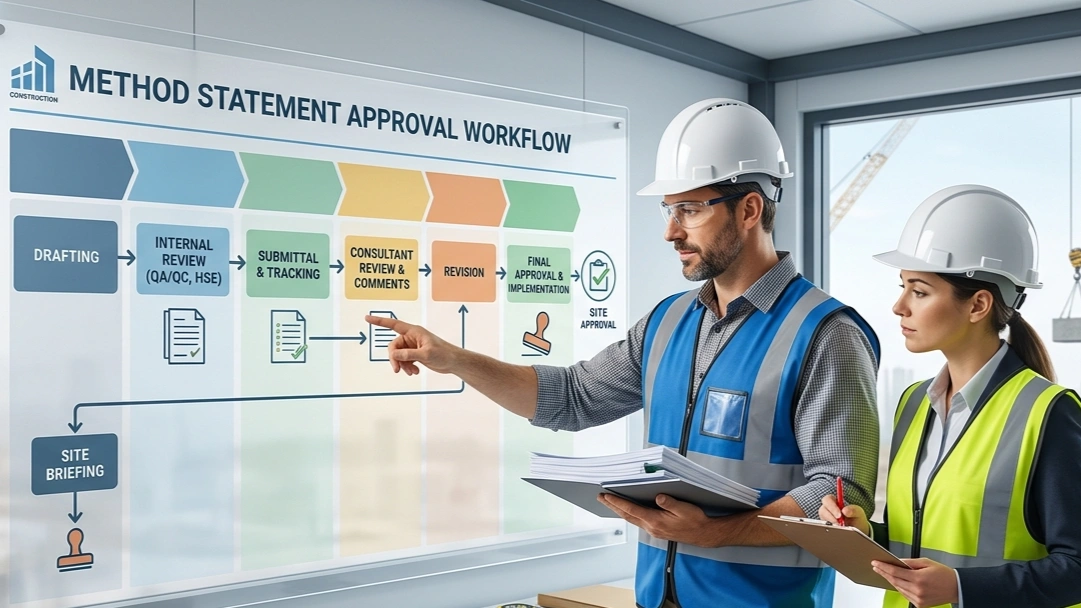
The method statement is prepared before the work activity starts and submitted as part of the pre-construction documentation package for review and approval.
Who reviews or approves it
The method statement is usually submitted to the client representative, consultant, resident engineer, or project management consultant for review and approval before the work commences.
Important approval note
This method statement is an AI-assisted editable starting point, not a pre-approved document. Before use on any project, all content must be reviewed and approved by the relevant parties (superintendent, principal contractor, or client representative) in accordance with your contract and project quality plan.
For example: if your specification requires a departure from a referenced standard, that departure must be documented and approved separately — this method statement will not capture that automatically. Always verify against your applicable drawings, specifications, and regulatory requirements.
Method statement content
Scope
Overview
This method statement covers the complete installation and commissioning of internal window roller blinds and automated motorized curtain tracking systems within building interiors, including:
- Pre-install window opening dimension checking and substrate verification
- Structural head fixing (blind box/headrail) and motorized barrel/track mounting
- Low-voltage (SELV/PELV) and/or mains voltage (e.g., 230 V AC) electrical connection coordination
- Functional setup: limit switch programming, calibration, group/scene configuration
- Remote control and BMS integration testing
- Cloth tracking/alignment and curtain carrier spacing adjustments
- Final cleaning, O&M documentation, training, and operational handover logs
Location
- Internal spaces of as indicated on approved architectural and interior design drawings [Verify per project drawings].
Exclusions
- Structural alterations to primary building elements beyond local fixings
- Provision of permanent power circuits upstream of isolators
- Penetration firestopping (unless otherwise specified)
- Access scaffolds/MEWPs beyond task-specific mobile equipment
Interfaces
- Architectural finishes (reveals, soffits, pelmets)
- MEP services (cable routes, isolators, containment)
- BMS/controls integration
- Glazing and façade elements
- Interior fit-out sequencing and access logistics
Key Performance Targets
- Headbox/track level tolerance: ≤2 mm across full width [Verify per manufacturer]
- Side light-gap (roller blinds, inside-recess): typically 10–18 mm per side; fabric cut deduction typically 30–35 mm from recess width [Verify per manufacturer]
- Track straightness/line: ≤2 mm deviation over any 2 m; cumulative ≤3 mm over full length [Verify]
- Bracket/support spacing: roller blind brackets at each end with additional center support for widths >2.5 m; motorized curtain track supports at 600 mm centers (straight) and 300–400 mm (curved/heavy) [Verify per manufacturer]
- Electrical tests per IEC/BS 7671; IR test ≥1 MΩ at 500 V DC (for 230 V circuits only). For SELV 24 V DC, continuity/polarity only [Verify]
- Limit set repeatability: ±2 mm; final stop accuracy: ±5 mm from datum [Verify]
- Group/scene synchronization: within 1 s across devices [Verify]
References
| Document Type | Reference / Number | Revision | Notes |
|---|---|---|---|
| Standard | BS EN 13120 | Includes child safety requirements; verify applicable national adoption. | |
| Standard | IEC/EN 60335-2-97 | Motorized drives compliance and testing. | |
| Standard | BS 7671 / IEC 60364 | LV/SELV circuit segregation, testing, and documentation [Verify local code]. | |
| Standard | BS 8539 | Anchor specification, edge distances, proof testing. | |
| Standard | BS 5867-2 | Type B/C classification typical; or NFPA 701 (USA) [Verify project]. | |
| Standard | ETSI EN 300 220 / EN 300 328; RED 2014/53/EU | For RF remotes/hubs [Verify region]. | |
| Standard | BS EN ISO 3506 | Use A2/A4 where moisture risk present. | |
| Standard | ISO 9001 | Contractor QA/QC framework. |
Responsibilities
| Role | Responsibility | Name / Party |
|---|---|---|
| PM | Ensure method compliance, coordinate interfaces, approve ITP | Contractor |
| Supervisor | Toolbox talks, permits, access, quality first-off | Contractor |
| Electrician | Compliance with BS 7671/IEC 60364, lockout/tagout | Contractor |
| Installer | Fixings selection, accurate set-out, bracket torque | Specialist Subcontractor |
| Commissioning Engineer | Limit setting, remote/BMS setup, functional testing | Specialist Subcontractor |
| QA/QC | Review ITP compliance, NCRs/SNAGs closure | Contractor |
| Engineer/Consultant | Witness key stages, approve handover | Employer/Consultant |
| OEM Rep | Confirm fixings, programming, and compatibility | Supplier |
Resources
| Resource Type | Description | Quantity | Remarks |
|---|---|---|---|
| Labor | 2–4 skilled installers per zone | Per program | |
| Labor | Terminations and testing | 1 per workface | |
| Labor | Programming and integration | Shared resource | |
| Labor | Certified MEWP user if required | As needed |
Materials
| Material | Specification / Grade | Quantity | Remarks |
|---|---|---|---|
| Roller blind assembly | OEM system; BS EN 13120 compliant [Verify] | ||
| Motorized track | Load rating ≥ curtain weight × 1.5 [Verify] | ||
| Drives | IEC/EN 60335-2-97 compliant; IP rating per location [Verify] | ||
| Controls | RED/ETSI compliant; interoperability with BMS [Verify] | ||
| Textiles | BS 5867-2 Type B/C or NFPA 701 [Verify]; VOC-free [Verify] | ||
| Anchors/Fasteners | To BS 8539; capacity ≥ 3 × factored load [Verify] | ||
| Electrical | BS 7671/IEC 60364 compliant; 0.75–1.5 mm² as designed [Verify] |
Equipment
| Equipment | Capacity / Type | Quantity | Inspection Required |
|---|---|---|---|
| Corded/cordless | Ø up to 12 mm | ||
| ±1 mm @ 10 m | |||
| 0.5–25 Nm | |||
| 500 V IR; continuity | |||
| As required | |||
| Multi-scanner | |||
| 0.5–2.5 mm² | |||
| Heat-shrink/adhesive |
Prerequisites
Documentation and Approvals
- Approved shop drawings, schedules, and coordination drawings showing fixings, headbox/tracks, and device IDs.
- Approved material submittals: motors, controls, fabrics (including fire certificates), fixings, and power supplies.
- ITP approved with defined Hold/Witness points.
- Risk Assessment and Method Statement (RAMS) approved; permits to work in place [Verify per project HSE plan and local regulations].
Site Readiness
- Final window opening dimensions available or accessible; plastering/painting complete at reveals/soffits unless otherwise agreed.
- Substrates accessible and load-bearing (concrete, steel, timber, or suitable drywall framing). Any weak/delaminated finishes rectified prior to installation.
- First-fix containment in place and tested; permanent power available at isolators or SELV PSU locations.
- Access made safe: MEWPs, towers, or ladders provided with inspection tags; fall protection where required.
Services and Coordination
- Services scan completed at head fix line for hidden MEP services.
- Power/control strategy confirmed: voltage, control topology (RF, dry contact, RS485, IP gateway), addressing plan, and grouping.
- Mock-up or first-off location identified for Client/Consultant witness.
Tools and Calibration
- Measuring tools, laser levels, torque tools, and test instruments calibrated with in-date certificates.
Training
- Installers and electricians briefed on OEM installation manuals and programming procedures.
Method Sequence
| Step | Activity | Description | Responsibility | Inspection / Hold Point |
|---|---|---|---|---|
| 1 | Pre-start briefing and permits | Conduct toolbox talk; review RAMS, drawings, and ITP. Obtain work permits and electrical isolation confirmations. | Site Supervisor | Permit verified; attendance recorded |
| 2 | Window opening survey | Measure recess width/height/depth at three points (top/mid/bottom). Note plumb and level deviations. Confirm handle/projection clashes. | Installer | First-off witness |
| 3 | Set-out and marking | Establish head line using laser. Mark bracket/anchor positions ensuring required edge distances and spacing. | Installer | In-process |
| 4 | Services scan and isolation | Scan head fixing zone for hidden services; confirm circuits isolated/locked if working near live conductors. | Electrician | Supervisor check |
| 5 | Drilling and anchor installation | Drill pilot/anchor holes with dust extraction. Install anchors per BS 8539, torque to OEM spec. Use cavity toggles in drywall with suitable backing. | Installer | Spot pull-out tests |
| 6 | Mount brackets/headbox or track supports | Fix brackets or track support clips to anchors. Shim as needed to achieve level/straightness. | Installer | Alignment check |
| 7 | Install roller barrel or curtain track | Fit motorized barrel/blind or assemble and hang motorized curtain track; ensure carriers/gliders at 8–12 per meter [Verify]. | Installer | Visual and mechanical |
| 8 | Electrical first fix/termination | Route and terminate power/control cables; maintain segregation LV/SELV. Fit isolators/PSUs in accessible locations. | Electrician | Continuity/polarity |
| 9 | Device addressing and pre-commission checks | Assign device IDs/channels; label motors, tracks, and controls. Verify travel is unobstructed. | Commissioning Engineer | Supervisor check |
| 10 | Limit switch programming/calibration | Set upper/lower (and intermediate) limits per drawings. Cycle three times to confirm repeatability. | Commissioning Engineer | Witness point (Consultant) |
| 11 | Remote/BMS integration | Pair remotes; configure groups/scenes. Integrate via dry-contact/RS485/IP gateway as specified. Verify fail-safe behavior on power loss. | Commissioning Engineer | Functional tests |
| 12 | Fabric/cloth tracking and alignment | Install fabric/curtain; adjust tracking to prevent telescoping or edge rubbing. Balance carrier loads. | Installer | Visual |
| 13 | Child-safety/cord devices (if any) | Fit tensioners/breakaway connectors; set cord/chain heights per standard. | Installer | Safety check |
| 14 | Cleaning and protection | Clean components; remove swarf/dust; protect finished items until handover. | Installer | Visual |
| 15 | Handover and training | Demonstrate operation; provide O&M manuals; gather sign-offs and warranties. | PM/Commissioning Engineer | Client witness (Hold Point) |
Safety Controls
Risk-Assessment Style Controls
- Hazard: Work at height (ladders/MEWPs) near windows
- Likely consequence: Falls causing serious injury or fatality
- Engineering/procedural control: Use inspected MEWP/tower with guardrails; maintain 3 points of contact on ladders; prohibit leaning into openings; install temporary edge protection/screens where possible; exclude leaning on glazing
- Required PPE: Hard hat, safety footwear, gloves, eye protection, fall-arrest harness with short lanyard when required
- Collective preventive measure: MEWP/tower with guardrails preferred over ladders; barricade below
-
Inspection/permit/supervision: Pre-use access inspection tags; MEWP operator license; Work at Height permit [Verify per project HSE plan and local regulations]
-
Hazard: Drilling into concealed services (electric, water, sprinkler, data)
- Likely consequence: Electrocution, flooding, service outage
- Engineering/procedural control: Scan with multi-scanner; review as-built drawings; impose no-drill exclusion zones; LOTO for nearby circuits; pilot drill with depth stop
- Required PPE: Insulated gloves (when testing), eye protection, hearing protection
- Collective preventive measure: Isolation of circuits; area cordon and signage
-
Inspection/permit/supervision: Permit to drill; Supervisor sign-off of scan records
-
Hazard: Manual handling of long tracks and blinds
- Likely consequence: Musculoskeletal injury; dropped objects
- Engineering/procedural control: Team lift; use handling aids/props; stage assemblies on padded trestles; limit individual lift to ≤25 kg [Verify per HSE guidance]
- Required PPE: Gloves, safety footwear
- Collective preventive measure: Mechanical aids/MEWP for high-level alignment
-
Inspection/permit/supervision: Manual handling briefing; supervisor oversight
-
Hazard: Power tools and flying swarf/dust
- Likely consequence: Eye injuries, inhalation, cuts
- Engineering/procedural control: Drill with integrated extraction; Class M vacuum; use sharp bits; keep guards in place; keep cables managed
- Required PPE: Safety glasses/face shield, hearing protection, gloves, FFP2/FFP3 mask when dusty
- Collective preventive measure: Local extraction and housekeeping; wet wipe of ledges
-
Inspection/permit/supervision: PAT testing; pre-use checks; supervision
-
Hazard: Electrical terminations and energization (SELV/230 V)
- Likely consequence: Electric shock, short circuit, fire
- Engineering/procedural control: Only qualified electrician; test dead; LOTO; use correct fusing/PSU ratings; segregate LV/SELV
- Required PPE: Insulated tools, arc-rated gloves as required, eye protection
- Collective preventive measure: Distribution isolation and temporary barriers
-
Inspection/permit/supervision: Electrical permit to work; BS 7671 testing records; supervision by Authorised Person
-
Hazard: Glass breakage at windows
- Likely consequence: Lacerations, falling glass
- Engineering/procedural control: Do not brace loads on glass; use padded standoffs; maintain clearance to glazing
- Required PPE: Cut-resistant gloves, eye protection
- Collective preventive measure: Temporary protection films/boards if at risk
-
Inspection/permit/supervision: Supervisor check during set-out
-
Hazard: Pinch/shear during motor movement and limit setting
- Likely consequence: Finger injuries
- Engineering/procedural control: Keep hands clear; jog at low speed; use OEM tools; establish exclusion zone during testing
- Required PPE: Gloves, eye protection
- Collective preventive measure: Signage and barrier tape
-
Inspection/permit/supervision: Commissioning supervised by competent person
-
Hazard: Public/other trades interface
- Likely consequence: Collision, dropped object injury
- Engineering/procedural control: Time windows for lifts; spotter; exclusion zone below workface; tool lanyards at height
- Required PPE: Standard site PPE
- Collective preventive measure: Barriers and signage; coordination meetings
-
Inspection/permit/supervision: Daily coordination with site management
-
Hazard: Chemical anchors (if used)
- Likely consequence: Skin/eye irritation; sensitization
- Engineering/procedural control: Follow SDS; adequate ventilation; correct mixing and cure time; do not overload before cure
- Required PPE: Chemical-resistant gloves, eye protection
- Collective preventive measure: Substitute with mechanical anchors where feasible
- Inspection/permit/supervision: COSHH assessment; storage inspection
[Verify per project HSE plan and local regulations]
Environmental Controls
Practical Controls
- Dust management: Use on-tool extraction and Class M vacuum; damp-wipe finishes post-drilling; prevent dust on HVAC/grilles.
- Noise control: Schedule drilling during permitted hours; use low-vibration tools; provide hearing protection and acoustic screens if necessary.
- Waste segregation: Segregate packaging (cardboard/plastic), metal offcuts, fabric/textile offcuts, and WEEE (motors, drivers, batteries). Dispose per project waste plan; recycle where facilities exist.
- Chemical management: Store adhesives/chemical anchors in bunded trays; prevent spills; hold SDS on site; use low-VOC sealants/adhesives [Verify necessity].
- Energy use: De-energize tools when not in use; consolidate commissioning to minimize run-time.
- RF emissions: Configure only required transmit power and avoid unnecessary test transmissions; comply with ETSI/RED [Verify region].
- Housekeeping: Daily clean-down; no swarf or offcuts left on window sills; protect finished surfaces with breathable coverings.
QA/QC
Quality Objectives and Controls
- Compliance with approved drawings, OEM manuals, and referenced standards.
- First-off installation witnessed and signed prior to repetition.
Tolerances and Metrics
- Head/track level: ≤2 mm across unit width; line straightness ≤2 mm over 2 m.
- Side gaps and deductions: As per OEM; typical roller blind fabric deduction 30–35 mm from recess width; verify per project.
- Fixings: Edge distances and embedment per BS 8539/OEM; sample pull-out ≥1.5 × design load [Verify].
- Electrical: IR ≥1 MΩ @ 500 V DC for 230 V circuits; correct polarity and earthing. For SELV, continuity and polarity only.
- Programming: Limits within ±5 mm of datum; repeatability ±2 mm over three cycles; group sync within 1 s.
Inspection and Testing Frequency
- Material verification: 100% on delivery (certificates, models, finishes).
- Fixing pull-out tests: 10% of fixings per substrate type or minimum 3 per area [Verify project requirement].
- Electrical tests: 100% of circuits.
- Functional tests: 100% of devices; 10% re-test after 24 h burn-in (where feasible) [Verify].
Records and Deliverables
- Survey sheets, fixing logs, torque logs, pull-test reports, electrical test sheets, commissioning sheets, device maps, labels, photos, O&M manuals, training sign-off, warranties (minimum 12–24 months typical [Verify per contract]).
- NCR and punch list management with corrective actions verified prior to handover.
Attachments
- Approved shop drawings and schedules
- OEM installation/commissioning manuals
- RAMS and permits
- Calibration certificates for laser, torque tools, and electrical testers
- Material certificates (compliance, fire performance, RED/ETSI)
- Sample checklists: Survey, Set-out, Fixing/Torque, Electrical Tests, Commissioning, Alignment, Child-Safety
- Device addressing and grouping register
- O&M manuals, spare parts lists, warranties
- Training and handover sign-off forms
This content is a read-only public reference. Download or customize to get an editable version.
ITP preview
The first inspection activities from the linked ITP for Method Statement: Installation of Internal Window Roller Blinds and Automated Motorized Curtain Tracking Systems:
| Activity | Inspection / Test | Acceptance Criteria | Responsibility | Record |
|---|---|---|---|---|
| Material delivery inspection | Verify model numbers, finishes, certificates (BS 5867, OEM docs) | Materials match approved submittals; certificates present and valid | QA/QC Inspector | Material inspection report |
| Pre-install survey (Hold Point) | Recess W/H/D at three points; level/plumb | Within stated tolerances; clashes resolved via RFI if outside | Site Supervisor / Consultant | Survey sheet; Consultant sign-off |
| Set-out verification | Laser level and spacing check | Level ±2 mm; spacing/edge distances per OEM/BS 8539 | QA/QC Inspector | Set-out checklist |
Showing 3 of 15 inspection activities. View full ITP →
Related Inspection and Test Plan
An Inspection and Test Plan (ITP) is available for Method Statement: Installation of Internal Window Roller Blinds and Automated Motorized Curtain Tracking Systems. The ITP defines the inspection activities, acceptance criteria, hold and witness points, responsible parties, and records required to verify the work described in this method statement.
View the Method Statement: Installation of Internal Window Roller Blinds and Automated Motorized Curtain Tracking Systems ITP →Frequently asked questions
Continue with related Quollnet resources connected to this method statement.