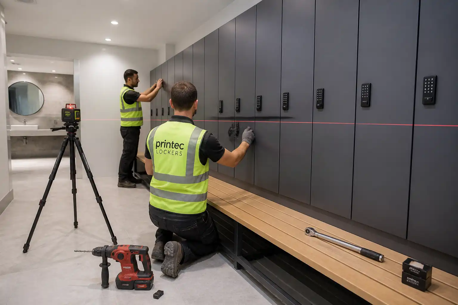

Method Statement: Installation of Internal Metal Lockers, Electronic Digital Locks, and Integrated Bench Seating – Method Statement
AI-assisted method statement with matching ITP, PDF download, and Excel export.
More than a static template
Unlike a downloadable Word or PDF template, this method statement is an AI-assisted editable starting point connected directly to a matching Inspection and Test Plan. Every section is structured, project-adaptable, and ready to export.
- AI-assisted drafting — Customize every section with AI for your specific project scope.
- Linked ITP — A matching inspection and test plan is generated alongside the method statement.
- Multiple export formats — Download as a formatted PDF or editable Excel spreadsheet.
- Editable starting point, not a final document — Review, verify, and adjust all content against your project requirements before use.
Static template vs. Quollnet workflow
| Feature | Static template | Quollnet |
|---|---|---|
| Project-specific content | Manual fill-in required | AI-assisted customization |
| Linked ITP | Separate document, no link | Matching ITP included |
| Export formats | Usually PDF only | PDF and Excel |
| Structured sections | Free-form layout | 13 standardized sections |
| Saved to your account | Local file only | Cloud-saved, reusable |
| Content accuracy | You verify everything | AI-assisted, you still verify |
| Cost | Often free but time-intensive | Free to customize and download |
What you can customize
When you save this method statement to your account, every section becomes editable. The following 13 sections are included:
- Scope — Defines the activity and its boundaries.
- References — Standards, specifications, and drawings.
- Responsibilities — Roles and accountabilities.
- Resources — Labour, plant, and equipment summary.
- Materials — Materials and compliance requirements.
- Equipment — Tools and equipment details.
- Prerequisites — Hold points and pre-conditions.
- Method sequence — Step-by-step construction sequence.
- Safety controls — HSE risk controls and PPE.
- Environmental controls — Environmental mitigation measures.
- QA/QC — Quality inspection and test requirements.
- ITP — Inspection and Test Plan table (has its own page).
- Attachments — Referenced drawings and documentation.
Why this method statement is used
This method statement is used to define and communicate the approved procedure for carrying out method statement: installation of internal metal lockers, electronic digital locks, and integrated bench seating on site. It ensures the work is planned in advance, the correct resources and controls are in place, and all personnel understand responsibilities, sequence, quality requirements, and safety controls before work begins. It aligns site execution with the documented scope and acceptance expectations.
Who uses this method statement
This method statement is used by contractors, site supervisors, project engineers, QA/QC engineers, HSE officers, consultants, and client representatives. It serves as a shared reference for planning, execution, supervision, inspection, and approval of the activity on site.
When it is prepared and submitted
The method statement is prepared before the work activity starts and submitted as part of the pre-construction documentation package for review and approval.
Who reviews or approves it
The method statement is usually submitted to the client representative, consultant, resident engineer, or project management consultant for review and approval before the work commences.
Important approval note
This method statement is an AI-assisted editable starting point, not a pre-approved document. Before use on any project, all content must be reviewed and approved by the relevant parties (superintendent, principal contractor, or client representative) in accordance with your contract and project quality plan.
For example: if your specification requires a departure from a referenced standard, that departure must be documented and approved separately — this method statement will not capture that automatically. Always verify against your applicable drawings, specifications, and regulatory requirements.
Method statement content
Scope
Overview
This method statement details the end-to-end installation of internal metal lockers with electronic digital lock modules and integrated bench seating within changing rooms. It includes substrate/plinth preparation and leveling, locker unit setting out, ganging, wall-tie anchoring, electronic lock battery installation and master programming/calibration, timber bench slat fixing, alignment and performance checks, documentation, and handover.
Included Activities
- Pre-installation surveys, permits to drill, and substrate verification.
- Floor plinth preparation: grinding, patch repair, self-leveling screed application, and tolerance checks.
- Delivery, unloading, staging, unpacking, and inspection of lockers, benches, and accessories.
- Setting out, ganging (unit-to-unit connection), leveling/shimming, and fixing to plinths.
- Wall-tie/anti-tip anchoring to solid or framed substrates, including proof testing.
- Installation of integrated bench frames and timber slats/seat tops beneath lockers where specified.
- Installation and commissioning of electronic digital lock modules, batteries, programming and calibration.
- Alignment checks, door and latch functional testing, sampling tests, snag rectification, cleaning, protection.
- Compilation of QA/QC records, warranties, as-built drawings, lock schedules, training, and final handover.
Exclusions
- Builder’s work outside the plinth levelling stated above (e.g., major screed rework beyond localized leveling).
- MEP modifications, electrical wiring to mains, or IT integrations not expressly required by the lock manufacturer.
- Structural design of anchors beyond typical selection and proof testing; final design loads to be confirmed by the Engineer.
Tolerances and Performance Targets [Verify per project specifications]
- Plinth levelness: ±3 mm over a 2 m straightedge; local variation ≤2 mm over 300 mm.
- Locker plumb/level: ≤2 mm deviation over full locker height/width.
- Face offset between adjacent locker faces: ≤1 mm; door gaps uniform within ±1 mm.
- Bench seating height: 450 ±5 mm; slat spacing 8–12 mm; screw spacing 300–400 mm c/c.
- Anchor proof load: 1.5 × service load or 3 kN minimum (whichever governs), displacement ≤1.0 mm at proof load, no slip or damage.
- Digital lock commissioning: 100% pass on 10 operating cycles per door; sample 10% subjected to 100 cycles without fault.
References
| Document Type | Reference / Number | Revision | Notes |
|---|---|---|---|
| Standard | BS EN 16121 | Performance and safety requirements for lockers in non-domestic use. | |
| Standard | BS EN 16122 | Applicable for site functional checks where practical. | |
| Standard | EN 1992-4 | Anchor design basis; use ETA-approved systems. | |
| Standard | BS 8539 | Covers roles, selection, installation, and testing of anchors. | |
| Guidance/Approval | ETA/EAD (Anchors) | Product-specific approvals for mechanical/chemical anchors. | |
| Standard | EN 13813 | For cementitious self-levelling compound selection. | |
| Standard | IEC 60086 | Battery safety and marking for digital locks. | |
| Regulation | RoHS/REACH/WEEE | For locks/batteries disposal and compliance. | |
| Standard | ISO 45001 | Framework for HSE management. | |
| Standard | ISO 9001 | Contractor/supplier quality management framework. | |
| Manual | OEM Manuals | Take precedence for product-specific steps if more stringent. |
Responsibilities
| Role | Responsibility | Name / Party |
|---|---|---|
| Project Manager | Project Manager | Contractor |
| Site Manager | Site Manager / Construction Supervisor | Contractor |
| QA/QC | QA/QC Engineer | Contractor |
| HSE | HSE Manager | Contractor |
| Engineer | Site Engineer / Surveyor | Contractor |
| Supervisor/Trades | Joinery Supervisor & Carpenters | Contractor |
| Crew | Locker Installation Crew Leader & Technicians | Contractor |
| Technician | Locks Commissioning Technician | Contractor/OEM |
| 3rd Party | Approved Third-Party Testing Agency | Independent |
Resources
| Resource Type | Description | Quantity | Remarks |
|---|---|---|---|
| Supervisor | Project/Site management | 2–3 [Verify per project] | |
| Technicians | Locker installation crew | 4–6 [Verify per project] | |
| Trades | Bench frame and slats | 2–3 | |
| Technician | Programming/calibration | 1–2 | |
| Specialists | HSE manager, QA/QC engineer | 1 each | |
| Labour | Material handling, protection | 2–3 |
Materials
| Material | Specification / Grade | Quantity | Remarks |
|---|---|---|---|
| Lockers | Gauge/thickness per OEM [Verify]. Finish RAL per schedule. | ||
| Lock modules | Per OEM; include escutcheons, strike plates, fixings. | ||
| Batteries | Brand/model per approved submittal. | ||
| Timber slats | Moisture content 8–12% [Verify]. Finish: sealed/varnished per spec. | ||
| Bench frames | Load rating per design [Verify]. | ||
| Anchors | Size/grade/edge distances per design [Verify]. | ||
| Fasteners | Lengths and heads per OEM details [Verify]. | ||
| Screed/SL | CT-C30-F7 or as specified [Verify]. | ||
| Shims/Isolators | Non-corroding, compressive strength suitable [Verify]. |
Equipment
| Equipment | Capacity / Type | Quantity | Inspection Required |
|---|---|---|---|
| Laser level | |||
| SDS drill + M-class extractor | |||
| Torque wrench 2–50 Nm | |||
| 0–20 kN pull tester | |||
| Scanner | |||
| Podium/steps | |||
| Trolleys/pallet truck | |||
| Assorted tools |
Prerequisites
- Approved submittals for lockers, benches, locks, anchors, batteries, and finishes.
- Confirm room readiness: walls and floors complete, MEP first/second fix complete, lighting operational, ambient conditions 10–30°C and RH 30–65% for timber stability [Verify per spec].
- Confirm plinth dimensions/locations vs. drawings; ensure structural capacity of substrates for fixing and imposed loads [Verify].
- Services scan and mark-out of walls/plinths (GPR/ferroscan/multidetector). Obtain Permit to Drill where required.
- Design confirmation for anchor types, embedment, edge distances, and load assumptions; method for framed partitions (locate studs/ply backing) [Verify per project].
- Calibrations in date for laser, torque wrench, pull tester; pre-use inspections logged.
- Deliveries scheduled; storage area dry, level, protected; acclimatize timber slats ≥24 h in room conditions.
- Task Briefing/RA/MS induction for all operatives; toolbox talk on manual handling and drilling hazards.
- Inspection and Test Plan (ITP) approved; WIR notifications issued in line with hold/witness points.
- Protection materials ready (floor, finished walls/fixtures).
Method Sequence
| Step | Activity | Description | Responsibility | Inspection / Hold Point |
|---|---|---|---|---|
| 1 | Pre-start and setting out | Verify drawings, datum, and locker/bench grid. Establish control lines on walls and floors; mark fixing centers avoiding services. | Site Engineer | Surveillance / WIR |
| 2 | Plinth preparation & leveling | Grind high spots, fill voids; apply primer and self-leveling compound as needed. Cure/protect per OEM. | Installation Crew | Witness (Client/Consultant) |
| 3 | Unpack, inspect, stage | Unpack lockers/benches on protected floor; check for damage, verify counts and finishes. Stage by bay sequence. | Crew Lead | Surveillance |
| 4 | Base placement & shimming | Position first locker in bay on plinth; install HDPE shims to achieve level and plumb; maintain bottom clearance 5–10 mm. | Installer | Surveillance |
| 5 | Ganging lockers | Align adjacent lockers; clamp and fix through OEM ganging holes using stainless bolts/washers. Typical spacing at top/mid/bottom ~300–400 mm c/c or per OEM. | Installer | Surveillance |
| 6 | Fix to plinth/base | Secure base to plinth using OEM base rails or brackets with appropriate anchors/screws. Use isolators where specified. | Installer | Witness |
| 7 | Wall-tie/anti-tip anchoring | Scan wall again at fixing points; drill to specified diameter/depth with dust extraction; clean holes; install ETA anchors per OEM/engineer. For stud walls, fix to studs/ply backing using structural screws. | Installer | Hold Point (before drilling) / Witness (installation) |
| 8 | Anchor proof load testing (sample) | Test 5% of anchors (min 3 per wall line) to specified proof load using pull tester with appropriate adaptor. | QA/QC or 3rd Party | Witness (Consultant) |
| 9 | Bench frame installation | Fix bench brackets/rails to lockers or wall/plinth per detail. Check height, projection, and rigidity. | Joinery Supervisor | Surveillance / Witness |
| 10 | Timber slat installation | Pre-drill/countersink; fix slats to frames with stainless screws. Maintain uniform spacing. Seal cut ends. | Carpenter | Surveillance |
| 11 | Electronic lock install | Mount lock bodies and strikes; route cables (if any) within door/carcass; fit batteries observing polarity; confirm battery voltage as required. | Lock Technician | Witness (as required) |
| 12 | Programming & calibration | Set master credentials/site code; calibrate latch/handing; set operating mode (private/public). Record serials and door numbers. | Lock Technician | Witness |
| 13 | Alignment and functional checks | Check plumb/level, reveals, door swing, latch strike engagement, soft bumpers, numbering plates. | QA/QC Engineer | Witness |
| 14 | Door latch performance testing | Operate each lock/door for 10 full cycles (open/close/lock). Randomly sample 10% for 100 cycles. | QA/QC / Technician | Witness |
| 15 | Cleaning and protection | Remove debris; clean surfaces; install protective film/covers until handover. | Crew Lead | Surveillance |
| 16 | Handover documentation and training | Compile O&M, warranties, anchor test certificates, torque logs, lock schedules/serials, spare keys/cards, battery data. Provide user training and sign-off. | Project Manager | Hold Point (Final) |
Health, Safety, and Environment (HSE) – Task-Specific Safety Controls
Key Hazards and Controls
- Hazard: Drilling into hidden services (electric, water, fire systems)
- Likely consequence: Electrocution, flooding, system impairment.
- Engineering/procedural control: Mandatory wall scan (GPR/ferroscan/multidetector) and mark-out; review as-built MEP; Permit to Drill; trial holes with non-percussive drill where risk remains.
- Required PPE: Safety glasses, cut-resistant gloves, RPE (FFP2/3) when drilling, hearing protection.
- Collective preventive measure: Exclusion zone with barriers; lockout/tagout of nearby circuits if applicable.
-
Inspection/permit/supervision: Permit to Drill, supervisor sign-off, pre-use tool checks. [Verify per project HSE plan and local regulations]
-
Hazard: Silica dust and debris from drilling/grinding
- Likely consequence: Respiratory irritation, long-term illness.
- Engineering/procedural control: On-tool M-class extraction; wet suppression for grinding if compatible; vacuum cleanup (no dry sweeping).
- PPE: FFP3 respirators, goggles.
- Collective measure: Local exhaust ventilation; dust screens as needed.
-
Inspection/permit/supervision: Equipment inspection log; RPE fit testing records.
-
Hazard: Manual handling of lockers/benches (bulk, awkward shape)
- Likely consequence: Musculoskeletal injury, crush/pinch.
- Engineering/procedural control: Team lifts with handling aids (trolleys/dollies), route planning, keep doors removed/secured during carry.
- PPE: Safety footwear (S3), cut-resistant gloves, back support as needed.
- Collective measure: Mechanical aids, floor edge protection, keep routes clear.
-
Inspection/permit/supervision: Manual handling briefing; supervisor oversight during moves.
-
Hazard: Working at height (top fixings/anchoring)
- Likely consequence: Falls, dropped objects.
- Engineering/procedural control: Use podium steps with guardrails; 3-point contact; tool lanyards.
- PPE: Hard hats, non-slip footwear, harness only if using MEWP/where required.
- Collective measure: Exclusion zone below; toe boards on podiums.
-
Inspection/permit/supervision: Pre-use access equipment inspection; WAH permit where required.
-
Hazard: Sharp edges and power tools
- Likely consequence: Lacerations, eye injury.
- Engineering/procedural control: Deburr edges; use guards; correct bits/speeds; isolate tools before bit change.
- PPE: Safety glasses, gloves.
- Collective measure: Bench-mounted work area, clamp workpieces.
-
Inspection/permit/supervision: PAT test and daily checks; competent users only.
-
Hazard: Battery handling for locks
- Likely consequence: Chemical irritation/leak, short-circuit heating.
- Engineering/procedural control: Use OEM-specified cells; insert with correct polarity; do not mix old/new; store in original packs; collect spent cells in insulated container.
- PPE: Nitrile gloves for leakers, eye protection.
- Collective measure: Battery spill kit; designated container for WEEE.
-
Inspection/permit/supervision: MSDS on site; waste consignment notes.
-
Hazard: Noise/vibration from drilling
- Likely consequence: Hearing damage, hand-arm vibration.
- Engineering/procedural control: Low-vibration tools; limit exposure time; task rotation.
- PPE: Hearing protection (SNR per site assessment), anti-vibration gloves.
- Collective measure: Schedule noisy works off-peak; signage.
-
Inspection/permit/supervision: HAV monitoring where required.
-
Hazard: Fire risk from hot works (if any cutting required)
- Likely consequence: Fire, smoke.
- Engineering/procedural control: Avoid hot works where possible; if unavoidable, Hot Work Permit, fire watch, extinguishers.
- PPE: Flame-resistant gloves, eye/face protection.
- Collective measure: Remove combustibles; fire blankets.
- Inspection/permit/supervision: Hot Work Permit, fire watch log.
Note: All controls to be verified against the Project HSE Plan and local regulations. Conduct daily point-of-work risk assessments and toolbox talks.
Environmental Controls
- Waste segregation: Separate metals, timber, cardboard/packaging, plastics, and WEEE (locks/batteries). Use labeled containers; maintain consignment records.
- Battery/WEEE disposal: Collect spent/leaking cells in insulated, ventilated containers; dispose via licensed carrier in compliance with WEEE/RoHS. Keep SDS available.
- Dust and air quality: On-tool extraction; FFP3 for operatives; maintain negative pressure or dust screens where sensitive areas adjoin.
- Noise: Limit drilling/grinding to agreed hours; use low-noise bits; provide hearing protection and signage.
- VOCs/chemicals: Select low-VOC primers/adhesives where used; keep lids closed; spill trays for chemicals.
- Timber sustainability: FSC/PEFC certificates retained; avoid unnecessary offcuts via pre-measurement; return unused full-lengths to supplier where possible.
- Housekeeping: Keep walkways clear; immediate cleanup of debris; protect finished floors/walls with approved coverings.
- Energy use: Use battery tools where feasible; switch off idle equipment; maintain chargers/PAT.
- Water: If wet grinding used, capture slurry and dispose per site procedure (no discharge to drains).
Quality Assurance and Quality Control
QA/QC Approach
- Compliance with approved submittals, standards (BS EN 16121/16122, EN 1992-4, BS 8539), and OEM manuals.
- Inspections per ITP with defined hold/witness points. WIRs raised 24–48 hours in advance [Verify].
- Tool calibration control for laser, torque wrench, and pull tester; certificates on file.
Key Checks & Tolerances [Verify per project]
- Plinth levelness: ±3 mm/2 m; local variation ≤2 mm over 300 mm.
- Locker plumb/level: ≤2 mm deviation full height/width; face offset ≤1 mm; door gaps uniform ±1 mm.
- Bench: height 450 ±5 mm; slat spacing 8–12 mm; screws 300–400 mm c/c; countersink flush ±0.5 mm.
- Anchors: embedment/edge distance per design; torque per OEM; proof load per spec (≥1.5 × service or 3 kN min).
- Locks: 100% commissioning pass; cycle test results recorded; master codes sealed for client.
Records
- Setting-out records, plinth level surveys, delivery inspections.
- Anchor installation logs, torque logs, pull test certificates.
- Programming/commissioning sheets; serial-to-door schedule; spare key/card registers.
- Checklists (locker install, bench install, alignment), NCR/CAR logs, as-builts, O&M manuals, warranties.
Defect Management
- Snag list compiled after initial QA; corrective actions tracked to closure with re-inspection and sign-off.
Attachments
- Approved shop drawings and coordination layouts (locker/bench/anchor details).
- OEM installation/commissioning manuals (lockers, benches, locks, anchors, SL compound).
- Risk Assessment & Method Statement (RAMS), permits (drilling, WAH, hot works if any).
- Calibration certificates (laser, torque wrench, pull tester), PAT records.
- Checklists: delivery, plinth level, locker install, bench install, alignment, functional tests.
- Anchor selection/design basis memo and ETA datasheets; torque charts.
- Programming/commissioning templates; lock serial-to-door schedule; sealed master credential record protocol.
- Waste management plan and WEEE/battery disposal procedure.
- Training materials and attendance records template.
This content is a read-only public reference. Download or customize to get an editable version.
ITP preview
The first inspection activities from the linked ITP for Method Statement: Installation of Internal Metal Lockers, Electronic Digital Locks, and Integrated Bench Seating:
| Activity | Inspection / Test | Acceptance Criteria | Responsibility | Record |
|---|---|---|---|---|
| Substrate/plinth verification | Levelness survey; visual soundness; adhesion (if tested) | Levelness ±3 mm/2 m; surface clean, dry, and sound [Verify] | QA/QC Engineer / Consultant | WIR, level survey sheet |
| Setting out approval | Check lines, centres, wall marks against drawings | Within ±3 mm; no conflicts with services | Site Engineer / Consultant | WIR, set-out record |
| Anchor installation (sample inspection) | Hole depth/diameter, cleaning method, torque value | Per OEM/design; torque within specified range [Verify] | QA/QC / Consultant | WIR, torque log, photos |
Showing 3 of 9 inspection activities. View full ITP →
Related Inspection and Test Plan
An Inspection and Test Plan (ITP) is available for Method Statement: Installation of Internal Metal Lockers, Electronic Digital Locks, and Integrated Bench Seating. The ITP defines the inspection activities, acceptance criteria, hold and witness points, responsible parties, and records required to verify the work described in this method statement.
View the Method Statement: Installation of Internal Metal Lockers, Electronic Digital Locks, and Integrated Bench Seating ITP →Frequently asked questions
Continue with related Quollnet resources connected to this method statement.